Page 4542 of 5883

RF-8
< FUNCTION DIAGNOSIS >
SUNROOF SYSTEM
FUNCTION DIAGNOSIS
SUNROOF SYSTEM
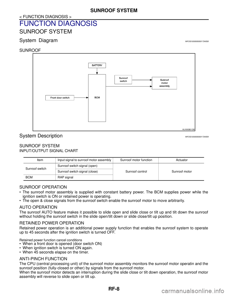
System DiagramINFOID:0000000001724558
SUNROOF
System DescriptionINFOID:0000000001724559
SUNROOF SYSTEM
INPUT/OUTPUT SIGNAL CHART
SUNROOF OPERATION
The sunroof motor assembly is supplied with constant battery power. The BCM supplies power while the
ignition switch is ON or retained power is operating.
The open & close signals from the sunroof switch enable the sunroof motor to move arbitrarily.
AUTO OPERATION
The sunroof AUTO feature makes it possible to slide open and slide close or tilt up and tilt down the sunroof
without holding the sunroof switch in the slide open/tilt down or slide close/tilt up position.
RETAINED POWER OPERATION
Retained power operation is an additional power supply function that enables the sunroof system to operate
up to 45 seconds after the ignition switch is turned OFF.
Retained power function cancel conditions
When a front door is opened (door switch ON)
When ignition switch is turned ON again.
When 45 seconds elapse on the timer.
ANTI-PINCH FUNCTION
The CPU (central processing unit) of the sunroof motor assembly monitors the sunroof motor operatin and the
sunroof position (fully-closed or other) by signals from the sunroof motor.
When the sunroof motor detects an interruption during the slide close or tilt down operation, the sunroof motor
assembly will reverse to slide open or tilt up.
ALKIA0861GB
Item Input signal to sunroof motor assembly Sunroof motor function Actuator
Sunroof switchSunroof switch signal (open)
Sunroof control Sunroof motor Sunroof switch signal (close)
BCM RAP signal
Page 4543 of 5883
SUNROOF SYSTEM
RF-9
< FUNCTION DIAGNOSIS >
C
D
E
F
G
H
I
J
L
MA
B
RF
N
O
P
Component Parts LocationINFOID:0000000001724560
Component DescriptionINFOID:0000000001724561
LIIA2597E
1.BCM M18, M20
(View with glove box removed)2. Sunroof switch R6 3. Sunroof motor assembly R4
4.Front door switch
LH B34
RH B27
Component Function
BCM Supplies power to the sunroof motor assembly.
Sunroof switch Transmits open & close operation signal to sunroof motor assembly.
Sunroof motor assemblyThe sunroof motor and integrated CPU enables tilt up/down & slide open/close as requested by
the sunroof switch.
Front door switch Detects door open/close condition and transmits to BCM.
Page 4544 of 5883

RF-10
< FUNCTION DIAGNOSIS >
DIAGNOSIS SYSTEM (BCM)
DIAGNOSIS SYSTEM (BCM)
COMMON ITEM
COMMON ITEM : CONSULT-III Function (BCM - COMMON ITEM)INFOID:0000000001724562
APPLICATION ITEM
CONSULT-III performs the following functions via CAN communication with BCM.
RETAINED PWR
RETAINED PWR : CONSULT-III Function (BCM - RETAINED PWR)INFOID:0000000001724563
WORK SUPPORT
DATA MONITOR
ACTIVE TEST
Diagnosis mode Function Description
WORK SUPPORT Changes the setting for each system function.
SELF-DIAG RESULTS Displays the diagnosis results judged by BCM. Refer to XX-XX, "*****"
.
CAN DIAG SUPPORT MNTR Monitors the reception status of CAN communication viewed from BCM.
DATA MONITOR The BCM input/output signals are displayed.
ACTIVE TEST The signals used to activate each device are forcibly supplied from BCM.
ECU IDENTIFICATION The BCM part number is displayed.
CONFIGURATION This function is not used even though it is displayed.
Work Support Item Description
RETAINED PWR SETMODE 1
MODE 2
MODE 3
Monitor Item Description
IGN ON SW Indicates [ON/OFF] condition of the ignition switch.
DOOR SW-DR Indicates [ON/OFF] condition of the front door switch LH.
DOOR SW-AS Indicates [ON/OFF] condition of the front door switch RH.
Active Test Item Description
RETAINED PWR Turns retained power function [ON/OFF].
Page 4549 of 5883

DOOR SWITCH
RF-15
< COMPONENT DIAGNOSIS >
C
D
E
F
G
H
I
J
L
MA
B
RF
N
O
P
DOOR SWITCH
DescriptionINFOID:0000000001724569
Detects door open/close condition and transmits the signal to BCM.
Component Function CheckINFOID:0000000001724570
1. CHECK DOOR SWITCH INPUT SIGNAL
Check (“DOOR SW-DR” and “DOOR SW-AS”) in “DATA MONITOR” mode with CONSULT-III.
Is the inspection result normal?
YES >> Door switch circuit is OK.
NO >> Refer to RF-15, "
Diagnosis Procedure".
Diagnosis ProcedureINFOID:0000000001724571
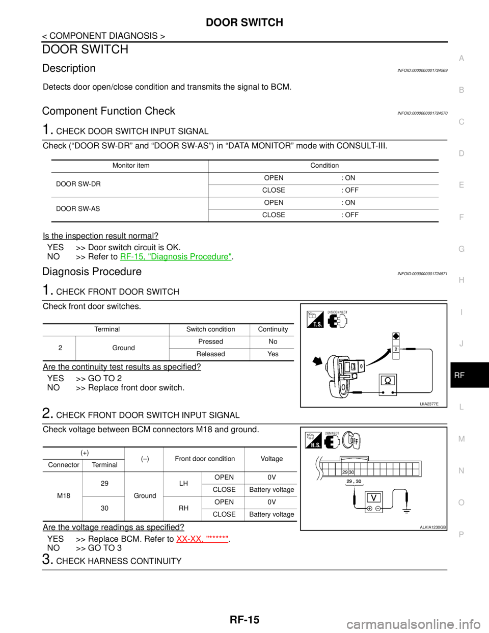
1. CHECK FRONT DOOR SWITCH
Check front door switches.
Are the continuity test results as specified?
YES >> GO TO 2
NO >> Replace front door switch.
2. CHECK FRONT DOOR SWITCH INPUT SIGNAL
Check voltage between BCM connectors M18 and ground.
Are the voltage readings as specified?
YES >> Replace BCM. Refer to XX-XX, "*****".
NO >> GO TO 3
3. CHECK HARNESS CONTINUITY
Monitor item Condition
DOOR SW-DROPEN : ON
CLOSE : OFF
DOOR SW-ASOPEN : ON
CLOSE : OFF
Terminal Switch condition Continuity
2GroundPressed No
Released Yes
LIIA2377E
(+)
(–) Front door condition Voltage
Connector Terminal
M1829
GroundLHOPEN 0V
CLOSE Battery voltage
30 RHOPEN 0V
CLOSE Battery voltage
ALKIA1230GB
Page 4550 of 5883
RF-16
< COMPONENT DIAGNOSIS >
DOOR SWITCH
1. Turn ignition switch OFF.
2. Disconnect BCM connectors M18 and front door switch connec-
tors B27 and B34.
3. Check continuity between BCM connectors M18 (A) and front
door switch connectors B27 and B34 (B).
4. Check continuity between BCM connectors M20 (A) and ground.
Are the continuity test results as specified?
YES >> Replace BCM. Refer to XX-XX, "*****".
NO >> Repair or replace harness.
AB
Continuity
Connector Terminal Connector Terminal
M1829 LH B34
2Yes
30 RH B27
A
— Continuity
Connector Terminal
M1829
Ground No
30
ALKIA1231GB
Page 4551 of 5883
BCM (BODY CONTROL MODULE)
RF-17
< ECU DIAGNOSIS >
C
D
E
F
G
H
I
J
L
MA
B
RF
N
O
P
ECU DIAGNOSIS
BCM (BODY CONTROL MODULE)
Reference ValueINFOID:0000000001724572
VALUES ON THE DIAGNOSIS TOOL
TERMINAL LAYOUT
Refer to XX-XX, "*****".
PHYSICAL VALUES
Refer to XX-XX, "*****".
WIRING DIAGRAM
Refer to XX-XX, "*****".
DTC INSPECTION
Refer to XX-XX, "*****".
DTC INDEX
Refer to XX-XX, "*****".
Monitor Item Condition Value/Status
DOOR SW-DRFront door LH closed OFF
Front door LH opened ON
DOOR SW-ASFront door RH closed OFF
Front door LH opened ON
Page 4552 of 5883

RF-18
< ECU DIAGNOSIS >
SUNROOF SYSTEM
SUNROOF SYSTEM
Reference ValueINFOID:0000000001724573
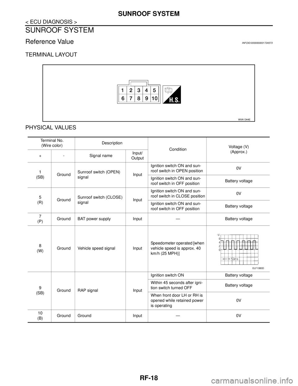
TERMINAL LAYOUT
PHYSICAL VALUES
WIIA1344E
Te r m i n a l N o .
(Wire color)Description
ConditionVoltage (V)
(Approx.)
+ - Signal nameInput/
Output
1
(SB)GroundSunroof switch (OPEN)
signalInputIgnition switch ON and sun-
roof switch in OPEN position0V
Ignition switch ON and sun-
roof switch in OFF positionBattery voltage
5
(R)GroundSunroof switch (CLOSE)
signalInputIgnition switch ON and sun-
roof switch in CLOSE position0V
Ignition switch ON and sun-
roof switch in OFF positionBattery voltage
7
(P)Ground BAT power supply Input — Battery voltage
8
(W)Ground Vehicle speed signal InputSpeedometer operated [when
vehicle speed is approx. 40
km/h (25 MPH)]
9
(SB)Ground RAP signal InputIgnition switch ON Battery voltage
Within 45 seconds after igni-
tion switch turned OFFBattery voltage
When front door LH or RH is
opened while retained power
is operating0V
10
(B)Ground Ground Input — 0V
ELF1080D
Page 4560 of 5883

RF-26
< SYMPTOM DIAGNOSIS >
SQUEAK AND RATTLE TROUBLE DIAGNOSES
The following materials, not available through NISSAN Parts Department, can also be used to repair squeaks
and rattles.
UHMW(TEFLON) TAPE
Insulates where slight movement is present. Ideal for instrument panel applications.
SILICONE GREASE
Used in place of UHMW tape that will be visible or not fit.
Note: Will only last a few months.
SILICONE SPRAY
Use when grease cannot be applied.
DUCT TAPE
Use to eliminate movement.
CONFIRM THE REPAIR
Confirm that the cause of a noise is repaired by test driving the vehicle. Operate the vehicle under the same
conditions as when the noise originally occurred. Refer to the notes on the Diagnostic Worksheet.
Generic Squeak and Rattle TroubleshootingINFOID:0000000001724411
Refer to Table of Contents for specific component removal and installation information.
INSTRUMENT PANEL
Most incidents are caused by contact and movement between:
1. The cluster lid A and instrument panel
2. Acrylic lens and combination meter housing
3. Instrument panel to front pillar garnish
4. Instrument panel to windshield
5. Instrument panel pins
6. Wiring harnesses behind the combination meter
7. A/C defroster duct and duct joint
These incidents can usually be located by tapping or moving the components to duplicate the noise or by
pressing on the components while driving to stop the noise. Most of these incidents can be repaired by apply-
ing felt cloth tape or silicone spray (in hard to reach areas). Urethane pads can be used to insulate wiring har-
ness.
CAUTION:
Do not use silicone spray to isolate a squeak or rattle. If you saturate the area with silicone, you will
not be able to recheck the repair.
CENTER CONSOLE
Components to pay attention to include:
1. Shifter assembly cover to finisher
2. A/C control unit and cluster lid C
3. Wiring harnesses behind audio and A/C control unit
The instrument panel repair and isolation procedures also apply to the center console.
DOORS
Pay attention to the:
1. Finisher and inner panel making a slapping noise
2. Inside handle escutcheon to door finisher
3. Wiring harnesses tapping
4. Door striker out of alignment causing a popping noise on starts and stops
Tapping or moving the components or pressing on them while driving to duplicate the conditions can isolate
many of these incidents. You can usually insulate the areas with felt cloth tape or insulator foam blocks from
the NISSAN Squeak and Rattle Kit (J-43980) to repair the noise.
TRUNK
Trunk noises are often caused by a loose jack or loose items put into the trunk by the owner.
In addition look for:
1. Trunk lid bumpers out of adjustment