2007 NISSAN TIIDA front
[x] Cancel search: frontPage 4443 of 5883
![NISSAN TIIDA 2007 Service Repair Manual PCS
PRECAUTIONS
PCS-29
< PRECAUTION >[IPDM E/R]
C
D
E
F
G
H
I
J
K
L B A
O
P N
PRECAUTION
PRECAUTIONS
Precaution for Supplemental Restraint System (SRS) "AIR BAG" and "SEAT BELT
PRE-TENSIONER"
INFOID: NISSAN TIIDA 2007 Service Repair Manual PCS
PRECAUTIONS
PCS-29
< PRECAUTION >[IPDM E/R]
C
D
E
F
G
H
I
J
K
L B A
O
P N
PRECAUTION
PRECAUTIONS
Precaution for Supplemental Restraint System (SRS) "AIR BAG" and "SEAT BELT
PRE-TENSIONER"
INFOID:](/manual-img/5/57395/w960_57395-4442.png)
PCS
PRECAUTIONS
PCS-29
< PRECAUTION >[IPDM E/R]
C
D
E
F
G
H
I
J
K
L B A
O
P N
PRECAUTION
PRECAUTIONS
Precaution for Supplemental Restraint System (SRS) "AIR BAG" and "SEAT BELT
PRE-TENSIONER"
INFOID:0000000001697601
The Supplemental Restraint System such as “AIR BAG” and “SEAT BELT PRE-TENSIONER”, used along
with a front seat belt, helps to reduce the risk or severity of injury to the driver and front passenger for certain
types of collision. This system includes seat belt switch inputs and dual stage front air bag modules. The SRS
system uses the seat belt switches to determine the front air bag deployment, and may only deploy one front
air bag, depending on the severity of a collision and whether the front occupants are belted or unbelted.
Information necessary to service the system safely is included in the SR and SB section of this Service Man-
ual.
WARNING:
To avoid rendering the SRS inoperative, which could increase the risk of personal injury or death in
the event of a collision which would result in air bag inflation, all maintenance must be performed by
an authorized NISSAN/INFINITI dealer.
Improper maintenance, including incorrect removal and installation of the SRS, can lead to personal
injury caused by unintentional activation of the system. For removal of Spiral Cable and Air Bag
Module, see the SR section.
Do not use electrical test equipment on any circuit related to the SRS unless instructed to in this
Service Manual. SRS wiring harnesses can be identified by yellow and/or orange harnesses or har-
ness connectors.
Page 4457 of 5883
PG-2
< PRECAUTION >
PRECAUTIONS
PRECAUTION
PRECAUTIONS
Precaution for Supplemental Restraint System (SRS) "AIR BAG" and "SEAT BELT
PRE-TENSIONER"
INFOID:0000000001731064
The Supplemental Restraint System such as “AIR BAG” and “SEAT BELT PRE-TENSIONER”, used along
with a front seat belt, helps to reduce the risk or severity of injury to the driver and front passenger for certain
types of collision. Information necessary to service the system safely is included in the “SRS AIRBAG” and
“SEAT BELT” of this Service Manual.
WARNING:
• To avoid rendering the SRS inoperative, which could increase the risk of personal injury or death in
the event of a collision which would result in air bag inflation, all maintenance must be performed by
an authorized NISSAN/INFINITI dealer.
Improper maintenance, including incorrect removal and installation of the SRS, can lead to personal
injury caused by unintentional activation of the system. For removal of Spiral Cable and Air Bag
Module, see the “SRS AIRBAG”.
Do not use electrical test equipment on any circuit related to the SRS unless instructed to in this
Service Manual. SRS wiring harnesses can be identified by yellow and/or orange harnesses or har-
ness connectors.
Page 4462 of 5883
PWC-1
BODY EXTERIOR, DOORS, ROOF & VEHICLE SECURITY
C
D
E
F
G
H
I
J
L
M
SECTION PWC
A
B
PWC
N
O
P
CONTENTS
POWER WINDOW CONTROL SYSTEM
BASIC INSPECTION ....................................3
DIAGNOSIS AND REPAIR WORKFLOW ..........3
Work Flow .................................................................3
INSPECTION AND ADJUSTMENT .....................4
ADDITIONAL SERVICE WHEN REMOVING BAT-
TERY NEGATIVE TERMINAL .....................................
4
ADDITIONAL SERVICE WHEN REMOVING
BATTERY NEGATIVE TERMINAL : Description ......
4
ADDITIONAL SERVICE WHEN REMOVING
BATTERY NEGATIVE TERMINAL : Special Re-
pair Requirement .......................................................
4
ADDITIONAL SERVICE WHEN REPLACING
CONTROL UNIT ..........................................................
4
ADDITIONAL SERVICE WHEN REPLACING
CONTROL UNIT : Description ..................................
4
ADDITIONAL SERVICE WHEN REPLACING
CONTROL UNIT : Special Repair Requirement .......
4
FUNCTION DIAGNOSIS ...............................6
POWER WINDOW SYSTEM ...............................6
System Diagram .......................................................6
System Description ...................................................6
Component Parts Location ......................................8
Component Description .............................................8
DIAGNOSIS SYSTEM (BCM) ............................10
COMMON ITEM .........................................................10
COMMON ITEM : CONSULT-III Function (BCM -
COMMON ITEM) .....................................................
10
RETAINED PWR .......................................................10
RETAINED PWR : CONSULT-III Function (BCM -
RETAINED PWR) ...................................................
10
COMPONENT DIAGNOSIS .........................11
POWER SUPPLY AND GROUND CIRCUIT ......11
POWER WINDOW MAIN SWITCH ............................11
POWER WINDOW MAIN SWITCH : Description ....11
POWER WINDOW MAIN SWITCH : Component
Function Check ........................................................
11
POWER WINDOW MAIN SWITCH : Diagnosis
Procedure ................................................................
11
POWER WINDOW MAIN SWITCH : Component
Inspection ................................................................
14
POWER WINDOW MAIN SWITCH : Special Re-
pair Requirement .....................................................
16
FRONT POWER WINDOW SWITCH .........................16
FRONT POWER WINDOW SWITCH : Descrip-
tion ...........................................................................
16
FRONT POWER WINDOW SWITCH : Compo-
nent Function Check ................................................
16
FRONT POWER WINDOW SWITCH : Diagnosis
Procedure ................................................................
17
REAR POWER WINDOW SWITCH ...........................19
REAR POWER WINDOW SWITCH : Description ....19
REAR POWER WINDOW SWITCH : Component
Function Check ........................................................
19
REAR POWER WINDOW SWITCH : Diagnosis
Procedure ................................................................
19
REAR POWER WINDOW SWITCH : Component
Inspection ................................................................
21
POWER WINDOW MOTOR ..............................22
DRIVER SIDE .............................................................22
DRIVER SIDE : Description .....................................22
DRIVER SIDE : Component Function Check ..........22
DRIVER SIDE : Diagnosis Procedure .....................22
DRIVER SIDE : Component Inspection ...................23
DRIVER SIDE : Special Repair Requirement ..........23
PASSENGER SIDE ....................................................24
PASSENGER SIDE : Description ............................24
PASSENGER SIDE : Component Function Check
....
24
PASSENGER SIDE : Diagnosis Procedure ............24
Page 4463 of 5883

PWC-2
PASSENGER SIDE : Component Inspection .........25
REAR LH ...................................................................25
REAR LH : Description ...........................................25
REAR LH : Component Function Check ................25
REAR LH : Diagnosis Procedure ............................25
REAR LH : Component Inspection .........................26
REAR RH ..................................................................27
REAR RH : Description ..........................................27
REAR RH : Component Function Check ................27
REAR RH : Diagnosis Procedure ...........................27
REAR RH : Component Inspection ........................28
ENCODER .........................................................29
DRIVER SIDE ............................................................29
DRIVER SIDE : Description ....................................29
DRIVER SIDE : Component Function Check .........29
DRIVER SIDE : Diagnosis Procedure ....................29
DRIVER SIDE : Special Repair Requirement .........31
DOOR SWITCH .................................................32
Description ..............................................................32
Component Function Check ...................................32
Diagnosis Procedure ..............................................32
Component Inspection ............................................33
POWER WINDOW LOCK SWITCH ...................34
Description ..............................................................34
Component Function Check ...................................34
Special Repair Requirement ...................................34
ECU DIAGNOSIS ........................................35
BCM (BODY CONTROL MODULE) ..................35
Reference Value .....................................................35
POWER WINDOW MAIN SWITCH ....................36
Reference Value .....................................................36
Wiring Diagram - LHD - ..........................................38
Wiring Diagram - RHD - ..........................................45
Fail Safe .................................................................51
SYMPTOM DIAGNOSIS ............................53
NONE OF THE POWER WINDOWS CAN BE
OPERATED USING ANY SWITCH ...................
53
Diagnosis Procedure ...............................................53
DRIVER SIDE POWER WINDOW ALONE
DOES NOT OPERATE ......................................
54
Diagnosis Procedure ...............................................54
FRONT PASSENGER SIDE POWER WIN-
DOW ALONE DOES NOT OPERATE ...............
55
Diagnosis Procedure ...............................................55
REAR LH SIDE POWER WINDOW ALONE
DOES NOT OPERATE ......................................
56
Diagnosis Procedure ...............................................56
REAR RH SIDE POWER WINDOW ALONE
DOES NOT OPERATE ......................................
57
Diagnosis Procedure ...............................................57
ANTI-PINCH SYSTEM DOES NOT OPERATE
NORMALLY (DRIVER SIDE) ............................
58
Diagnosis Procedure ...............................................58
AUTO OPERATION DOES NOT OPERATE
BUT MANUAL OPERATE NORMALLY
(DRIVER SIDE) ..................................................
59
Diagnosis Procedure ...............................................59
POWER WINDOW RETAINED POWER OP-
ERATION DOES NOT OPERATE PROPERLY
...
60
Diagnosis Procedure ...............................................60
POWER WINDOW LOCK SWITCH DOES
NOT FUNCTION ................................................
61
Diagnosis Procedure ...............................................61
ON-VEHICLE MAINTENANCE ..................62
PRE-INSPECTION FOR DIAGNOSTIC ............62
Basic Inspection ......................................................62
Page 4467 of 5883
PWC-6
< FUNCTION DIAGNOSIS >
POWER WINDOW SYSTEM
FUNCTION DIAGNOSIS
POWER WINDOW SYSTEM
System DiagramINFOID:0000000001696298
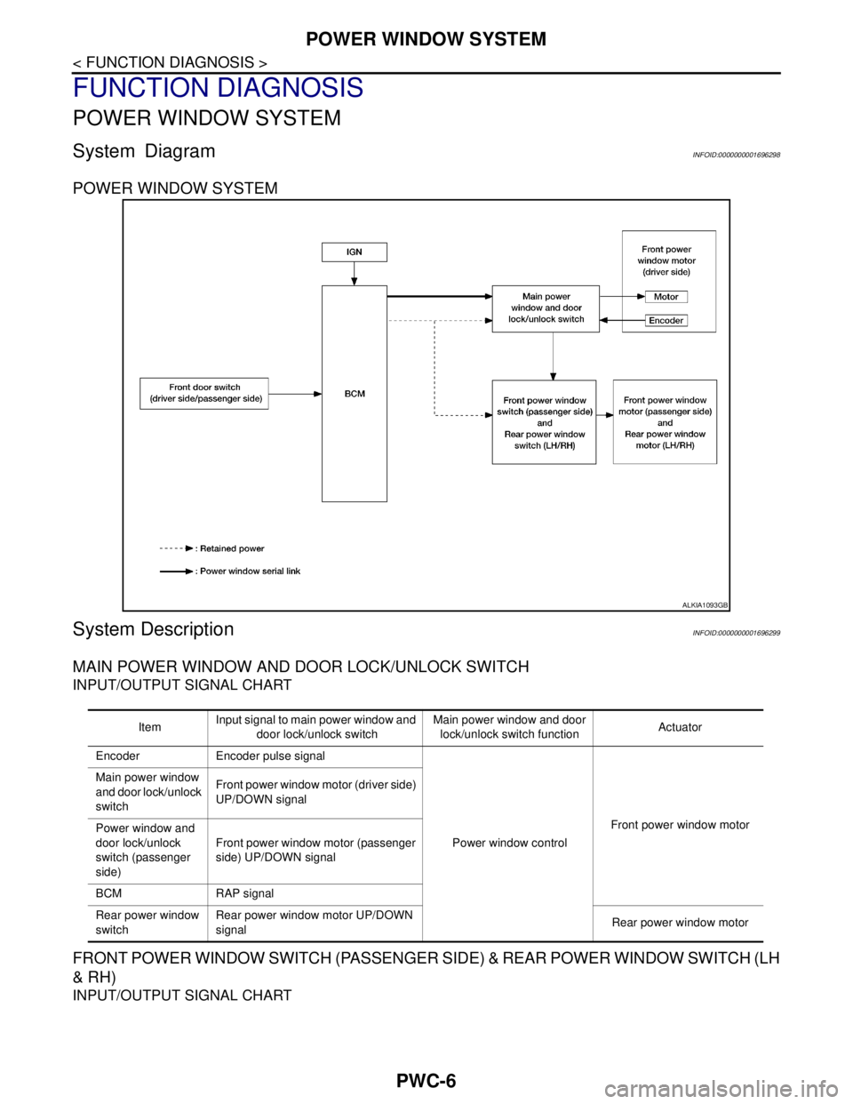
POWER WINDOW SYSTEM
System DescriptionINFOID:0000000001696299
MAIN POWER WINDOW AND DOOR LOCK/UNLOCK SWITCH
INPUT/OUTPUT SIGNAL CHART
FRONT POWER WINDOW SWITCH (PASSENGER SIDE) & REAR POWER WINDOW SWITCH (LH
& RH)
INPUT/OUTPUT SIGNAL CHART
ALKIA1093GB
ItemInput signal to main power window and
door lock/unlock switchMain power window and door
lock/unlock switch functionActuator
Encoder Encoder pulse signal
Power window controlFront power window motor Main power window
and door lock/unlock
switchFront power window motor (driver side)
UP/DOWN signal
Power window and
door lock/unlock
switch (passenger
side) Front power window motor (passenger
side) UP/DOWN signal
BCM RAP signal
Rear power window
switchRear power window motor UP/DOWN
signalRear power window motor
Page 4468 of 5883
POWER WINDOW SYSTEM
PWC-7
< FUNCTION DIAGNOSIS >
C
D
E
F
G
H
I
J
L
MA
B
PWC
N
O
P
POWER WINDOW OPERATION
Power window system is operable during the retained power operation timer after turning ignition switch ON
and OFF.
Main power window and door lock/unlock switch can open/close all windows.
Front & rear power window switches can open/close the corresponding windows.
POWER WINDOW AUTO-OPERATION (FRONT DRIVER SIDE)
AUTO UP/DOWN operation can be performed when main power window and door lock/unlock switch turns
to AUTO.
Encoder continues detecting the movement of power window motor and transmits to main power window
and door lock/unlock switch as the encoder pulse signal while power window motor is operating.
Main power window and door lock/unlock switch reads the changes of encoder signal and stops AUTO oper-
ation when door glass is at fully opened/closed position.
Power window motor is operable in case encoder is malfunctioning.
RETAINED POWER OPERATION
Retained power operation is an additional power supply function that enables power window system to oper-
ate during the 45 seconds even when ignition switch is turned OFF
Retained power function cancel conditions Front door CLOSE (door switch OFF)→OPEN (door switch ON).
When ignition switch is ON.
When timer time passes (45 seconds).
POWER WINDOW LOCK
Ground circuit inside main power window and door lock/unlock switch shuts off when power window lock
switch is ON. This inhibits power window switch operation except with the main power window and door lock/
unlock switch.
ANTI-PINCH OPERATION (FRONT DRIVER SIDE)
Pinch foreign material in the door glass during AUTO-UP operation,and it is the anti-pinch function that low-
ers the door glass 150 mm (5.9 in.) or 2 seconds when detected.
Encoder continues detecting the movement of power window motor and transmits to main power window
and door lock/unlock switch as the encoder pulse signal while power window motor is operating.
Resistance is applied to the power window motor rotation that changes the frequency of encoder pulse sig-
nal if foreign material is trapped in the door glass.
Power window switch controls to lower the window glass for 150 mm (5.9 in.) or 2 seconds after it detects
encoder pulse signal frequency change.
OPERATION CONDITION
When door glass AUTO-UP operation is performed (anti-pinch function does not operate just before the door
glass closes and is fully closed)
NOTE:
Depending on environment and driving conditions, if a similar impact or load is applied to the door glass, it
may lower.
Item Input signal to front power window
switch (passenger side) & rear power
window switch (LH & RH)Front power window switch
(passenger side) & rear power
window switch (LH & RH) func-
tionActuator
Front power window
switch (passenger
side)Front power window motor (passen-
ger side) UP/DOWN signal
Power window controlFront power window motor
(passenger side)
Rear power window
switch (LH & RH)Rear power window motor (LH & RH)
UP/DOWN signalRear power window motor (LH
& RH)
Page 4469 of 5883
PWC-8
< FUNCTION DIAGNOSIS >
POWER WINDOW SYSTEM
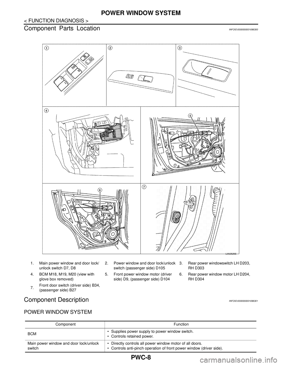
Component Parts Location
INFOID:0000000001696300
Component DescriptionINFOID:0000000001696301
POWER WINDOW SYSTEM
LIIA2529E
1. Main power window and door lock/
unlock switch D7, D82. Power window and door lock/unlock
switch (passenger side) D1053. Rear power windowswitch LH D203,
RH D303
4. BCM M18, M19, M20 (view with
glove box removed)5. Front power window motor (driver
side) D9, (passenger side) D1046. Rear power window motor LH D204,
RH D304
7.Front door switch (driver side) B34,
(passenger side) B27
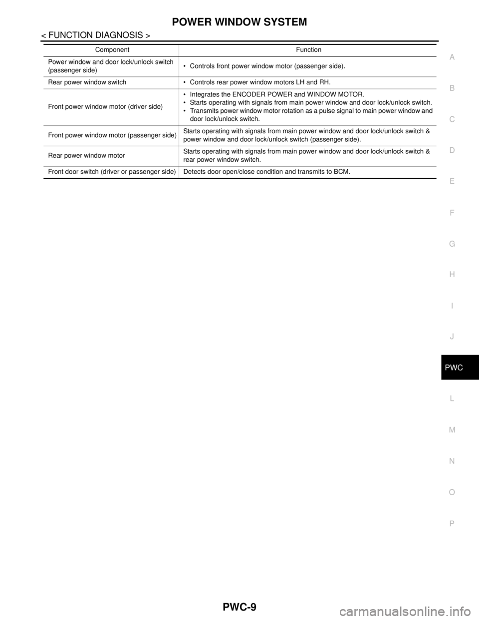
Component Function
BCM Supplies power supply to power window switch.
Controls retained power.
Main power window and door lock/unlock
switch Directly controls all power window motor of all doors.
Controls anti-pinch operation of front power window (driver side).
Page 4470 of 5883
POWER WINDOW SYSTEM
PWC-9
< FUNCTION DIAGNOSIS >
C
D
E
F
G
H
I
J
L
MA
B
PWC
N
O
P
Power window and door lock/unlock switch
(passenger side) Controls front power window motor (passenger side).
Rear power window switch Controls rear power window motors LH and RH.
Front power window motor (driver side) Integrates the ENCODER POWER and WINDOW MOTOR.
Starts operating with signals from main power window and door lock/unlock switch.
Transmits power window motor rotation as a pulse signal to main power window and
door lock/unlock switch.
Front power window motor (passenger side)Starts operating with signals from main power window and door lock/unlock switch &
power window and door lock/unlock switch (passenger side).
Rear power window motorStarts operating with signals from main power window and door lock/unlock switch &
rear power window switch.
Front door switch (driver or passenger side) Detects door open/close condition and transmits to BCM.Component Function