2007 NISSAN TIIDA front
[x] Cancel search: frontPage 4369 of 5883

MWI-62
< ECU DIAGNOSIS >
BCM (BODY CONTROL MODULE)
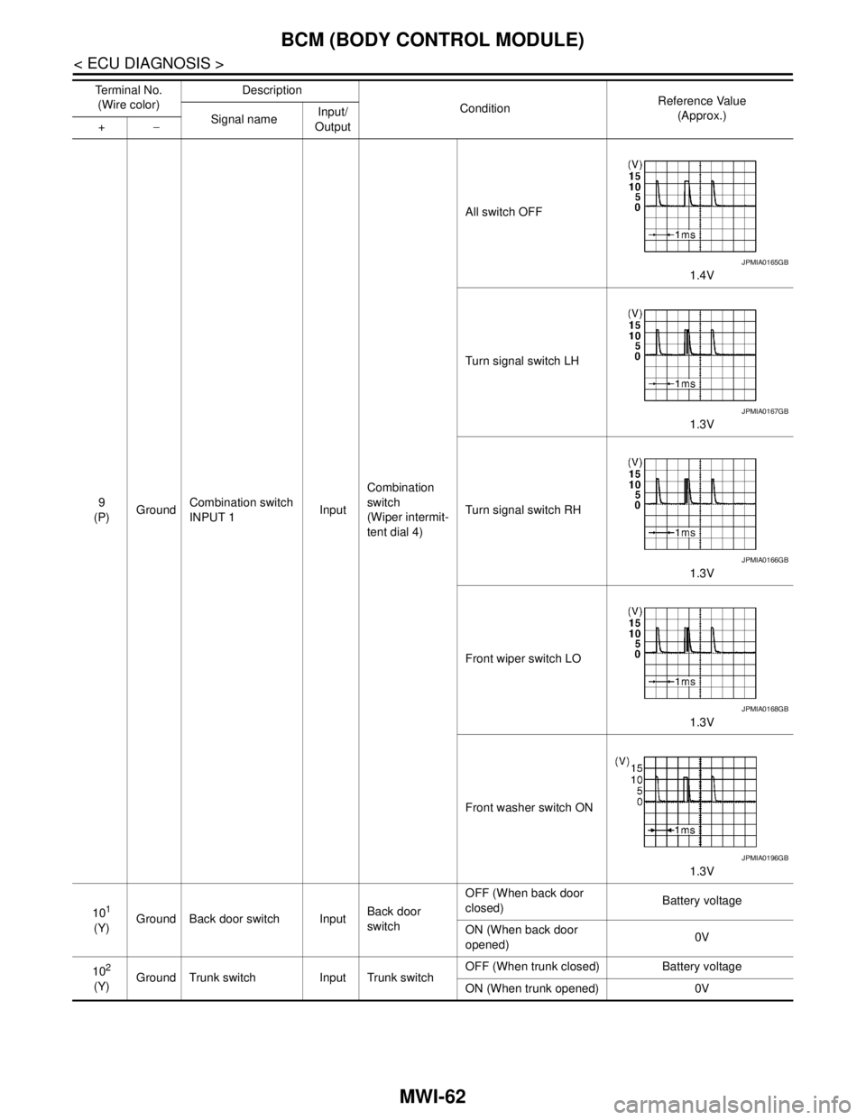
9
(P)GroundCombination switch
INPUT 1InputCombination
switch
(Wiper intermit-
tent dial 4)All switch OFF
1.4V
Turn signal switch LH
1.3V
Turn signal switch RH
1.3V
Front wiper switch LO
1.3V
Front washer switch ON
1.3V
10
1
(Y)Ground Back door switch InputBack door
switchOFF (When back door
closed)Battery voltage
ON (When back door
opened)0V
10
2
(Y)Ground Trunk switch Input Trunk switchOFF (When trunk closed) Battery voltage
ON (When trunk opened) 0V Te r m i n a l N o .
(Wire color)Description
ConditionReference Value
(Approx.)
Signal nameInput/
Output +−
JPMIA0165GB
JPMIA0167GB
JPMIA0166GB
JPMIA0168GB
JPMIA0196GB
Page 4370 of 5883

MWI
BCM (BODY CONTROL MODULE)
MWI-63
< ECU DIAGNOSIS >
C
D
E
F
G
H
I
J
K
L
MB A
O
P
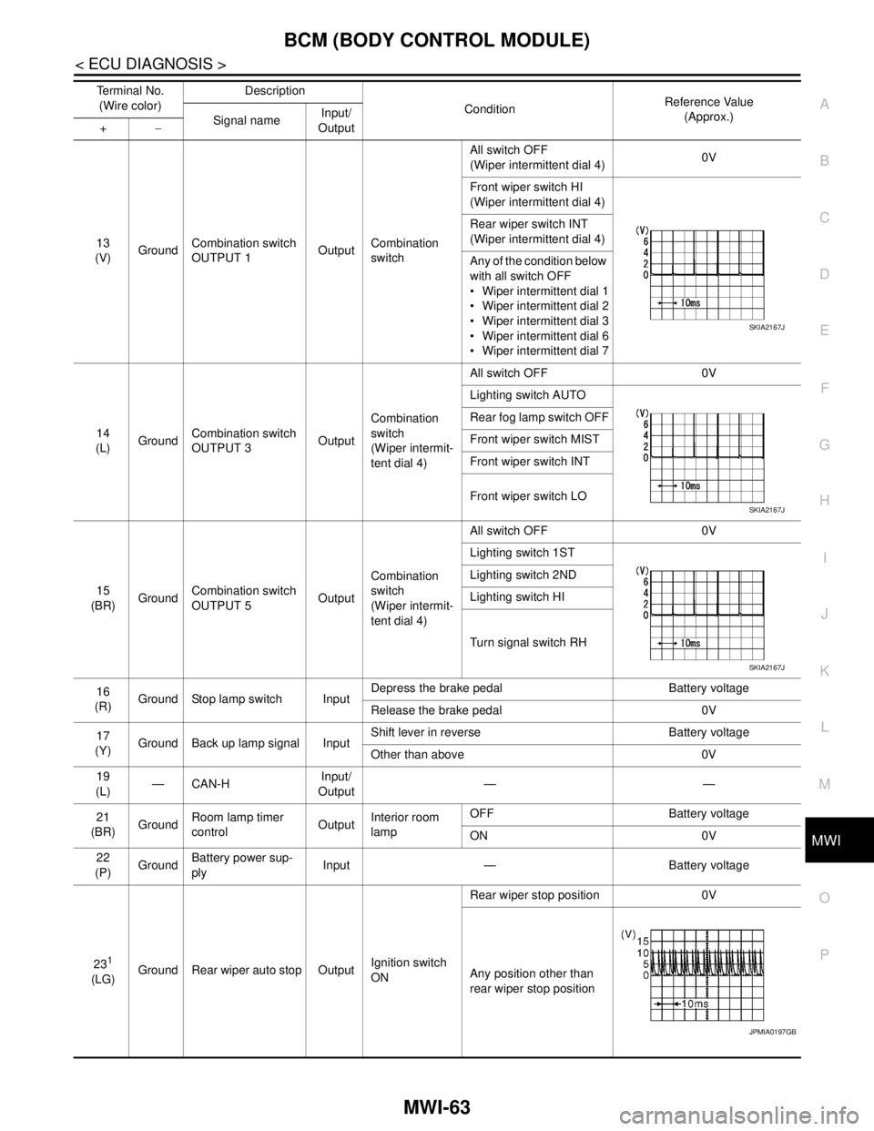
13
(V)GroundCombination switch
OUTPUT 1OutputCombination
switchAll switch OFF
(Wiper intermittent dial 4)0V
Front wiper switch HI
(Wiper intermittent dial 4)
Rear wiper switch INT
(Wiper intermittent dial 4)
Any of the condition below
with all switch OFF
Wiper intermittent dial 1
Wiper intermittent dial 2
Wiper intermittent dial 3
Wiper intermittent dial 6
Wiper intermittent dial 7
14
(L)GroundCombination switch
OUTPUT 3OutputCombination
switch
(Wiper intermit-
tent dial 4)All switch OFF 0V
Lighting switch AUTO
Rear fog lamp switch OFF
Front wiper switch MIST
Front wiper switch INT
Front wiper switch LO
15
(BR)GroundCombination switch
OUTPUT 5OutputCombination
switch
(Wiper intermit-
tent dial 4)All switch OFF 0V
Lighting switch 1ST
Lighting switch 2ND
Lighting switch HI
Turn signal switch RH
16
(R)Ground Stop lamp switch InputDepress the brake pedal Battery voltage
Release the brake pedal 0V
17
(Y)Ground Back up lamp signal InputShift lever in reverse Battery voltage
Other than above 0V
19
(L)—CAN-HInput/
Output——
21
(BR)GroundRoom lamp timer
controlOutputInterior room
lampOFF Battery voltage
ON 0V
22
(P)GroundBattery power sup-
plyInput — Battery voltage
23
1
(LG)Ground Rear wiper auto stop OutputIgnition switch
ONRear wiper stop position 0V
Any position other than
rear wiper stop position Terminal No.
(Wire color)Description
ConditionReference Value
(Approx.)
Signal nameInput/
Output +−
SKIA2167J
SKIA2167J
SKIA2167J
JPMIA0197GB
Page 4373 of 5883

MWI-66
< ECU DIAGNOSIS >
BCM (BODY CONTROL MODULE)
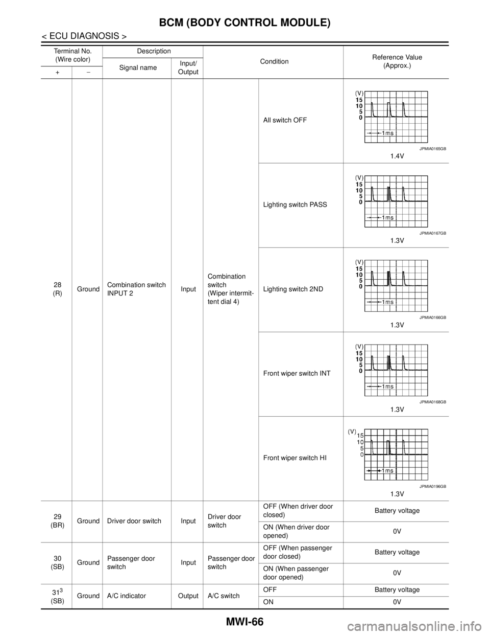
28
(R)GroundCombination switch
INPUT 2InputCombination
switch
(Wiper intermit-
tent dial 4)All switch OFF
1.4V
Lighting switch PASS
1.3V
Lighting switch 2ND
1.3V
Front wiper switch INT
1.3V
Front wiper switch HI
1.3V
29
(BR)Ground Driver door switch InputDriver door
switchOFF (When driver door
closed)Battery voltage
ON (When driver door
opened)0V
30
(SB)GroundPassenger door
switchInputPassenger door
switchOFF (When passenger
door closed)Battery voltage
ON (When passenger
door opened)0V
31
3
(SB)Ground A/C indicator Output A/C switchOFF Battery voltage
ON 0V Te r m i n a l N o .
(Wire color)Description
ConditionReference Value
(Approx.)
Signal nameInput/
Output +−
JPMIA0165GB
JPMIA0167GB
JPMIA0166GB
JPMIA0168GB
JPMIA0196GB
Page 4374 of 5883

MWI
BCM (BODY CONTROL MODULE)
MWI-67
< ECU DIAGNOSIS >
C
D
E
F
G
H
I
J
K
L
MB A
O
P
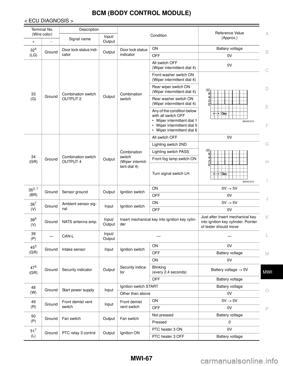
324
(LG)GroundDoor lock status indi-
catorOutputDoor lock status
indicatorON Battery voltage
OFF 0V
33
(G)GroundCombination switch
OUTPUT 2OutputCombination
switchAll switch OFF
(Wiper intermittent dial 4)0V
Front washer switch ON
(Wiper intermittent dial 4)
Rear wiper switch ON
(Wiper intermittent dial 4)
Rear washer switch ON
(Wiper intermittent dial 4)
Any of the condition below
with all switch OFF
Wiper intermittent dial 1
Wiper intermittent dial 5
Wiper intermittent dial 6
34
(GR)GroundCombination switch
OUTPUT 4OutputCombination
switch
(Wiper intermit-
tent dial 4)All switch OFF 0V
Lighting switch 2ND
Lighting switch PASS
Front fog lamp switch ON
Turn signal switch LH
35
3, 7
(BR)Ground Sensor ground Output Ignition switchON 0V → 5V
OFF 0V
36
7
(V)GroundAmbient sensor sig-
nalInput Ignition switchON 0V → 5V
OFF 0V
38
5
(V)Ground NATS antenna amp.Input/
OutputInsert mechanical key into ignition key cylin-
derJust after Insert mechanical key
into ignition key cylinder. Pointer
of tester should move
39
(P)—CAN-LInput/
Output——
45
3
(GR)Ground Intake sensor Input Ignition switchON 0V
OFF Battery voltage
47
5
(GR)Ground Security indicator OutputSecurity indica-
torON 0V
Blinking
(every 2.4 seconds)Battery voltage → 0V
OFF Battery voltage
48
(W)Ground Start power supply InputIgnition switch START Battery voltage
Other than above 0V
49
(R)GroundFront demist vent
switchInputFront demist
vent switchON 0V → 5V
OFF 0V
50
(P)Ground Fan switch Output Fan switchNot pressed Battery voltage
Pressed 0
51
7
(L)Ground PTC relay 3 control Output Ignition ONPTC heater 3 ON 0V
PTC heater 3 OFF Battery voltage Terminal No.
(Wire color)Description
ConditionReference Value
(Approx.)
Signal nameInput/
Output +−
SKIA2167J
SKIA2167J
Page 4376 of 5883

MWI
BCM (BODY CONTROL MODULE)
MWI-69
< ECU DIAGNOSIS >
C
D
E
F
G
H
I
J
K
L
MB A
O
P
1: Hatchback
2: Sedan
3: Manual A/C
4: Superlock
5: Remote keyless entry
6: Intelligent Key
7: LHD diesel69
(G)Ground Rear fog lamp OutputLighting switch
1ST and front
fog lamp switch
ONRear fog lamp switch OFF 0V
Rear fog lamp switch ON Battery voltage
70
(B)Ground Ground — — 0V
71
1
(V)Ground Rear wiper motor OutputRear wiper switch OFF 0V
Rear wiper switch ON Battery voltage
72
(LG)GroundBattery power sup-
plyInput — Battery voltage
73
(R)GroundInterior room lamp
power supplyOutputAfter passing the interior room lamp battery
saver operation time0V
Any other time after passing the interior room
lamp battery saver operation timeBattery voltage
74
(Y)GroundBattery power sup-
plyInput — Battery voltage
75
4
(V)Ground Super lock OutputWhen lock button of keyfob or Intelligent Key
is not pressed 0V
When lock button of keyfob or Intelligent Key
is pressed Battery voltage
76
(G)Ground Driver door unlock OutputDoor lock/un-
lock switchPressed to the unlock side Battery voltage
Pressed to the lock side 0V
77
(SB)Ground Door lock (All) OutputDoor lock/un-
lock switchPressed to the unlock side 0V
Pressed to the lock side Battery voltage
78
(L)GroundPower window pow-
er supplyOutput Ignition switchOFF or ACC 0V
ON Battery voltage
79
(Y)GroundBattery power sup-
plyInput — Battery voltage Terminal No.
(Wire color)Description
ConditionReference Value
(Approx.)
Signal nameInput/
Output +−
Page 4382 of 5883

MWI
IPDM E/R (INTELLIGENT POWER DISTRIBUTION MODULE ENGINE ROOM)
MWI-75
< ECU DIAGNOSIS >
C
D
E
F
G
H
I
J
K
L
MB A
O
P
IPDM E/R (INTELLIGENT POWER DISTRIBUTION MODULE ENGINE
ROOM)
Reference ValueINFOID:0000000001713125
VALUES ON THE DIAGNOSIS TOOL
Monitor Item Condition Value/Status
MOTOR FAN REQ Engine idle speedChanges depending on engine
coolant temperature, air conditioner
operation status, vehicle speed,
etc.0 - 100 %
A/C COMP REQA/C switch OFF OFF
A/C switch ON ON
TA I L & C L R R E QLighting switch OFF OFF
Lighting switch 1ST, 2ND, HI or AUTO (Light is illuminated) ON
HL LO REQLighting switch OFF OFF
Lighting switch 2ND HI or AUTO (Light is illuminated) ON
HL HI REQLighting switch OFF OFF
Lighting switch HI ON
FR FOG REQLighting switch 2ND or AUTO (Light
is illuminated)Front fog lamp switch OFF OFF
Front fog lamp switch ON
Daytime light activated ON
HL WASHER REQNOTE:
This item is displayed, but cannot be monitored.OFF
FR WIP REQ Ignition switch ONFront wiper switch OFF STOP
Front wiper switch INT 1LOW
Front wiper switch LO LOW
Front wiper switch HI HI
WIP AUTO STOP Ignition switch ONFront wiper stop position STOP P
Any position other than front wiper
stop positionACT P
WIP PROT Ignition switch ONFront wiper operates normally OFF
Front wiper stops at fail-safe opera-
tionBLOCK
ST RLY REQIgnition switch OFF or ACC OFF
Ignition switch START ON
IGN RLYIgnition switch OFF or ACC OFF
Ignition switch ON ON
RR DEF REQRear defogger switch OFF OFF
Rear defogger switch ON ON
OIL P SWIgnition switch OFF, ACC or engine running OPEN
Ignition switch ON CLOSE
DTRL REQNOTE:
This item is displayed, but cannot be monitored.OFF
HOOD SWNOTE:
This item is displayed, but cannot be monitored.OFF
Page 4386 of 5883

MWI
IPDM E/R (INTELLIGENT POWER DISTRIBUTION MODULE ENGINE ROOM)
MWI-79
< ECU DIAGNOSIS >
C
D
E
F
G
H
I
J
K
L
MB A
O
P
29 PTail lamp relay (park-
ing lamps)Output — Lighting switch in 2nd position Battery voltage
30 R Fuse 54 Output —Ignition switch ON or START Battery voltage
Ignition switch OFF or ACC 0V
31 O Fuse 55 Output —Ignition switch ON or START Battery voltage
Ignition switch OFF or ACC 0V
32 LWiper high speed sig-
nalOutputON or
STARTWiper switchOFF, LO, INT 0V
HI Battery voltage
33 YWiper low speed sig-
nalOutputON or
STARTWiper switchOFF 0V
LO or INT Battery voltage
35 BRStarter relay (inhibit
switch)InputON or
STARTSelector lever in "P" or "N"
(CVT or A/T) or clutch pedal
depressed (M/T)Battery voltage
Selector lever any other posi-
tion (CVT or A/T) or clutch
pedal released (M/T)0V
36 BR Fuel pump relay Output —Ignition switch ON or START Battery voltage
Ignition switch OFF or ACC 0V
37 G Oil pressure switch InputON or
STARTEngine running and oil pres-
sure within specificationBattery voltage
Engine not running or oil pres-
sure below specification0V
38 R Wiper auto stop signal InputON or
STARTWipers not in park position Battery voltage
Wipers in park position 0V
39 B Ground Input — — 0V
40 P CAN-L — ON — —
41 L CAN-H — ON — —
46 YThrottle control motor
relay controlInput —Ignition switch ON or START 0V
Ignition switch OFF or ACC Battery voltage
47 GRFuel pump relay con-
trolInput —Ignition switch ON or START 0V
Ignition switch OFF or ACC Battery voltage
50 V Front fog lamp (LH)Output ON or
STARTLighting
switch must
be in the 2ND
position
(LOW beam
is ON) and
the front fog
lamp switchOFF 0V
ON Battery voltage
51 W Front fog lamp (RH) OutputON or
STARTLighting
switch must
be in the 2ND
position
(LOW beam
is ON) and
the front fog
lamp switchOFF 0V
ON Battery voltage
52 LLH Low beam head-
lampOutput — Lighting switch in 2nd position Battery voltage Te r m i n a lWire
colorSignal name
Signal
input/
outputMeasuring condition
Reference value
(Approx.) Ignition
switchOperation or condition
Page 4392 of 5883

MWI
IPDM E/R (INTELLIGENT POWER DISTRIBUTION MODULE ENGINE ROOM)
MWI-85
< ECU DIAGNOSIS >
C
D
E
F
G
H
I
J
K
L
MB A
O
P If No CAN Communication Is Available With BCM
IGNITION RELAY MALFUNCTION DETECTION FUNCTION
IPDM E/R monitors the voltage at the contact circuit and excitation coil circuit of the ignition relay inside it.
IPDM E/R judges the ignition relay error if the voltage differs between the contact circuit and the excitation
coil circuit.
If the ignition relay cannot turn OFF due to contact seizure, it activates the tail lamp relay for 10 minutes to
alert the user to the ignition relay malfunction when the ignition switch is turned OFF.
NOTE:
The tail lamp turns OFF when the ignition switch is turned ON.
FRONT WIPER CONTROL
IPDM E/R detects front wiper stop position by a front wiper auto stop signal.
When a front wiper auto stop signal is in the conditions listed below, IPDM E/R stops power supply to wiper
after repeating a front wiper 10 second activation and 20 second stop five times.
NOTE:
This operation status can be confirmed on the IPDM E/R “DATA MONITOR” that displays “Block” for the item
“WIP PROT” while the wiper is stopped.
STARTER MOTOR PROTECTION FUNCTION
IPDM E/R turns OFF the starter control relay to protect the starter motor when the starter control relay remains
active for 90 seconds.
Control part Fail-safe in operation
Cooling fan Turns ON the cooling fan relay when the ignition switch is turned ON
Turns OFF the cooling fan relay when the ignition switch is turned OFF
Control part Fail-safe in operation
Headlamp Turns ON the headlamp low relay when the ignition switch is turned ON
Turns OFF the headlamp low relay when the ignition switch is turned OFF
Headlamp high relay OFF
Parking lamps
License plate lamps
Tail lamps Turns ON the tail lamp relay when the ignition switch is turned ON
Turns OFF the tail lamp relay when the ignition switch is turned OFF
Front wiper The status just before activation of fail-safe control is maintained until the ignition
switch is turned OFF while the front wiper is operating at LO or HI speed.
The wiper is operated at LO speed until the ignition switch is turned OFF if the fail-
safe control is activated while the front wiper is set in the INT mode and the front wiper
motor is operating.
Rear window defogger Rear window defogger relay OFF
A/C compressor A/C relay OFF
Front fog lamps Front fog lamp relay OFF
Ignition switch Ignition relay Tail lamp relay
ON ON —
OFF OFF —
Ignition switch Front wiper switch Auto stop signal
ONOFFFront wiper stop position signal cannot be
input 10 seconds.
ON The signal does not change for 10 seconds.