2007 NISSAN TIIDA front
[x] Cancel search: frontPage 4471 of 5883

PWC-10
< FUNCTION DIAGNOSIS >
DIAGNOSIS SYSTEM (BCM)
DIAGNOSIS SYSTEM (BCM)
COMMON ITEM
COMMON ITEM : CONSULT-III Function (BCM - COMMON ITEM)INFOID:0000000001696302
APPLICATION ITEM
CONSULT-III performs the following functions via CAN communication with BCM.
SYSTEM APPLICATION
BCM can perform the following functions for each system.
NOTE:
It can perform the diagnosis modes except the following for all sub system selection items.
RETAINED PWR
RETAINED PWR : CONSULT-III Function (BCM - RETAINED PWR)INFOID:0000000001696303
Data monitor
Diagnosis mode Function Description
WORK SUPPORT Changes the setting for each system function.
SELF-DIAG RESULTS Displays the diagnosis results judged by BCM. Refer to BCS-54, "
DTCIndex".
CAN DIAG SUPPORT MNTR Monitors the reception status of CAN communication viewed from BCM.
DATA MONITOR The BCM input/output signals are displayed.
ACTIVE TEST The signals used to activate each device are forcibly supplied from BCM.
ECU IDENTIFICATION The BCM part number is displayed.
CONFIGURATION This function is not used even though it is displayed.
System Sub system selection itemDiagnosis mode
WORK SUPPORT DATA MONITOR ACTIVE TEST
BCM BCM×
RAP system RETAINED PWR×
Monitor Item Description
DOOR SW-DR Indicates [ON/OFF] condition of front door switch LH.
DOOR SW-AS Indicates [ON/OFF] condition of front door switch RH.
Page 4476 of 5883
POWER SUPPLY AND GROUND CIRCUIT
PWC-15
< COMPONENT DIAGNOSIS >
C
D
E
F
G
H
I
J
L
MA
B
PWC
N
O
P
( ): RHD
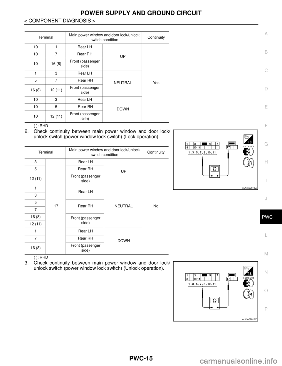
2. Check continuity between main power window and door lock/
unlock switch (power window lock switch) (Lock operation).
( ): RHD
3. Check continuity between main power window and door lock/
unlock switch (power window lock switch) (Unlock operation).
Te r m i n a lMain power window and door lock/unlock
switch conditionContinuity
10 1 Rear LH
UP
Ye s 10 7 Rear RH
10 16 (8)Front (passenger
side)
13 Rear LH
NEUTRAL 5 7 Rear RH
16 (8) 12 (11)Front (passenger
side)
10 3 Rear LH
DOWN 10 5 Rear RH
10 12 (11)Front (passenger
side)
Te r m i n a lMain power window and door lock/unlock
switch conditionContinuity
3
17Rear LH
UP
No 5Rear RH
12 (11)Front (passenger
side)
1
Rear LH
NEUTRAL 3
5
Rear RH
7
16 (8)
Front (passenger
side)
12 (11)
1 Rear LH
DOWN 7Rear RH
16 (8)Front (passenger
side)
ALKIA0281ZZ
ALKIA0281ZZ
Page 4477 of 5883
PWC-16
< COMPONENT DIAGNOSIS >
POWER SUPPLY AND GROUND CIRCUIT
( ): RHD
Is the inspection result normal?
YES >> Main power window and door lock/unlock switch is OK.
NO >> Replace main power window and door lock/unlock switch. Refer to INT-13, "
Removal and Installa-
tion". After that, refer to PWC-16, "POWER WINDOW MAIN SWITCH : Special Repair Require-
ment".
POWER WINDOW MAIN SWITCH : Special Repair RequirementINFOID:0000000001696308
1. PERFORM INITIALIZATION PROCEDURE
Perform initialization procedure.
Refer to PWC-4, "
ADDITIONAL SERVICE WHEN REPLACING CONTROL UNIT : Special Repair Require-
ment"
Is the inspection result normal?
YES >> GO TO 2
NO >> Check intermittent incident. Refer to GI-55, "
Intermittent Incident".
2. CHECK ANTI-PINCH OPERATION
Check anti-pinch operation.
Refer to PWC-4, "
ADDITIONAL SERVICE WHEN REPLACING CONTROL UNIT : Special Repair Require-
ment"
Is the inspection result normal?
YES >> Inspection end.
NO >> Refer to PWC-14, "
POWER WINDOW MAIN SWITCH : Component Inspection"
FRONT POWER WINDOW SWITCH
FRONT POWER WINDOW SWITCH : DescriptionINFOID:0000000001696309
BCM supplies power.
Front power window motor (passenger side) will be operated if power window and door lock/unlock switch
(passenger side) is operated.
FRONT POWER WINDOW SWITCH : Component Function CheckINFOID:0000000001696310
Power Window And Door Lock/unlock Switch (Passenger Side)
1. CHECK FRONT POWER WINDOW MOTOR (PASSENGER SIDE) FUNCTION
Te r m i n a lMain power window and door lock/un-
lock switch conditionContinuity
3
17Rear LH
UP
Ye s 5Rear RH
12 (11)Front (passenger
side)
1
Rear LH
NEUTRAL 3
5
Rear RH
7
16 (8)
Front (passenger
side)
11
1 Rear LH
DOWN 7Rear RH
8Front (passenger
side)
Page 4478 of 5883
POWER SUPPLY AND GROUND CIRCUIT
PWC-17
< COMPONENT DIAGNOSIS >
C
D
E
F
G
H
I
J
L
MA
B
PWC
N
O
P
Does front power window motor (passenger side) operate with power window and door lock/unlock switch
(passenger side) operation?
Is the inspection result normal?
YES >> Power window and door lock/unlock switch (passenger side) power supply and ground circuit are
OK.
NO >> Refer to PWC-17, "
FRONT POWER WINDOW SWITCH : Diagnosis Procedure".
FRONT POWER WINDOW SWITCH : Diagnosis ProcedureINFOID:0000000001696311
Power Window And Door Lock/Unlock Switch (Passenger Side) Power Supply Circuit Check
1. CHECK POWER SUPPLY CIRCUIT
1. Turn ignition switch ON.
2. Check voltage between power window and door lock/unlock switch (passenger side) connector and
ground.
( ): RHD
Is the measurement value within the specification?
YES >> GO TO 3
NO >> GO TO 2
2. CHECK HARNESS CONTINUITY
1. Turn ignition switch OFF.
2. Disconnect BCM and power window and door lock/unlock switch (passenger side).
3. Check continuity between BCM connector and power window and door lock/unlock switch (passenger
side) connector.
( ): RHD
4. Check continuity between BCM connector (A) and ground.
Is the inspection result normal?
YES >> GO TO 4
NO >> Repair or replace harness.
3. CHECK HARNESS CONTINUITY [POWER WINDOW AND DOOR LOCK/UNLOCK SWITCH PASSEN-
GER SIDE)]
1. Turn ignition switch OFF.
2. Disconnect main power window and door lock/unlock switch and power window and door lock/unlock
switch (passenger side).
3. Check continuity between main power window and door lock/unlock switch connector and power window
and door lock/unlock switch (passenger side) connector.
Te r m i n a l
Voltage (V)
(Approx.) (+)
(–) Power window and door
lock/unlock
switch (passenger side)
connectorTe r m i n a l
D105 1 (8) Ground Battery voltage
BCM connector TerminalPower window and door
lock/unlock switch (pas-
senger side) connectorTerminal Continuity
M20 68 D105 1 (8) Yes
BCM connector Terminal
GroundContinuity
M20 68 No
Page 4479 of 5883
PWC-18
< COMPONENT DIAGNOSIS >
POWER SUPPLY AND GROUND CIRCUIT
( ): RHD
4. Check continuity between main power window and door lock/unlock switch connector (A) and ground.
( ): RHD
Is the inspection result normal?
YES >> Check intermittent incident. Refer to GI-55, "Intermittent Incident".
NO >> Repair or replace harness.
4. CHECK BCM OUTPUT SIGNAL
1. Connect BCM.
2. Turn ignition switch ON.
3. Check voltage between power window and door lock/unlock switch (passenger side) connector and
ground.
( ): RHD
Is the measurement value within the specification?
YES >> GO TO 5
NO >> Repair or replace harness.
5. CHECK POWER WINDOW AND DOOR LOCK/UNLOCK SWITCH (PASSENGER SIDE)
Check power window and door lock/unlock switch (passenger side).
Refer to PWC-16, "
FRONT POWER WINDOW SWITCH : Component Function Check".
Is the inspection result normal?
YES >> Check intermittent incident. Refer to GI-55, "Intermittent Incident".
NO >> Replace power window and door lock/unlock switch (passenger side). Refer to INT-13, "
Removal
and Installation".
COMPONENT INSPECTION
1. CHECK POWER WINDOW AND DOOR LOCK/UNLOCK SWITCH (PASSENGER SIDE)
Check power window and door lock/unlock switch (passenger side).
Main power win-
dow and door
lock/unlock
switch connectorTe r m i n a lPower window
and door lock/un-
lock switch (pas-
senger side)
connectorTerminal Continuity
D712 (11)
D1053 (11)
Ye s
16 (8) 2 (12)
Main power window and door lock/
unlock switch connectorTerminal
GroundContinuity
D712 (11)
No
16 (8)
Te r m i n a l
Voltage (V)
(Approx.) (+)
(–) Power window and door
lock/unlock switch (pas-
senger side) connectorTe r m i n a l
D105 1 (8) Ground Battery voltage
Page 4483 of 5883
PWC-22
< COMPONENT DIAGNOSIS >
POWER WINDOW MOTOR
POWER WINDOW MOTOR
DRIVER SIDE
DRIVER SIDE : DescriptionINFOID:0000000001696316
Door glass moves UP/DOWN by receiving the signal from main power window and door lock/unlock switch.
DRIVER SIDE : Component Function CheckINFOID:0000000001696317
1. CHECK FRONT POWER WINDOW MOTOR (DRIVER SIDE) CIRCUIT
Does front power window motor (driver side) operate with the main power window and door lock/unlock
switch?
Is the inspection result normal?
YES >> Front power window motor (driver side) is OK.
NO >> Refer to PWC-22, "
DRIVER SIDE : Diagnosis Procedure".
DRIVER SIDE : Diagnosis ProcedureINFOID:0000000001696318
Front Power Window Motor LH Circuit Check
1. CHECK MAIN POWER WINDOW AND DOOR LOCK/UNLOCK SWITCH OUTPUT SIGNAL
1. Disconnect front power window motor (driver side).
2. Turn ignition switch ON.
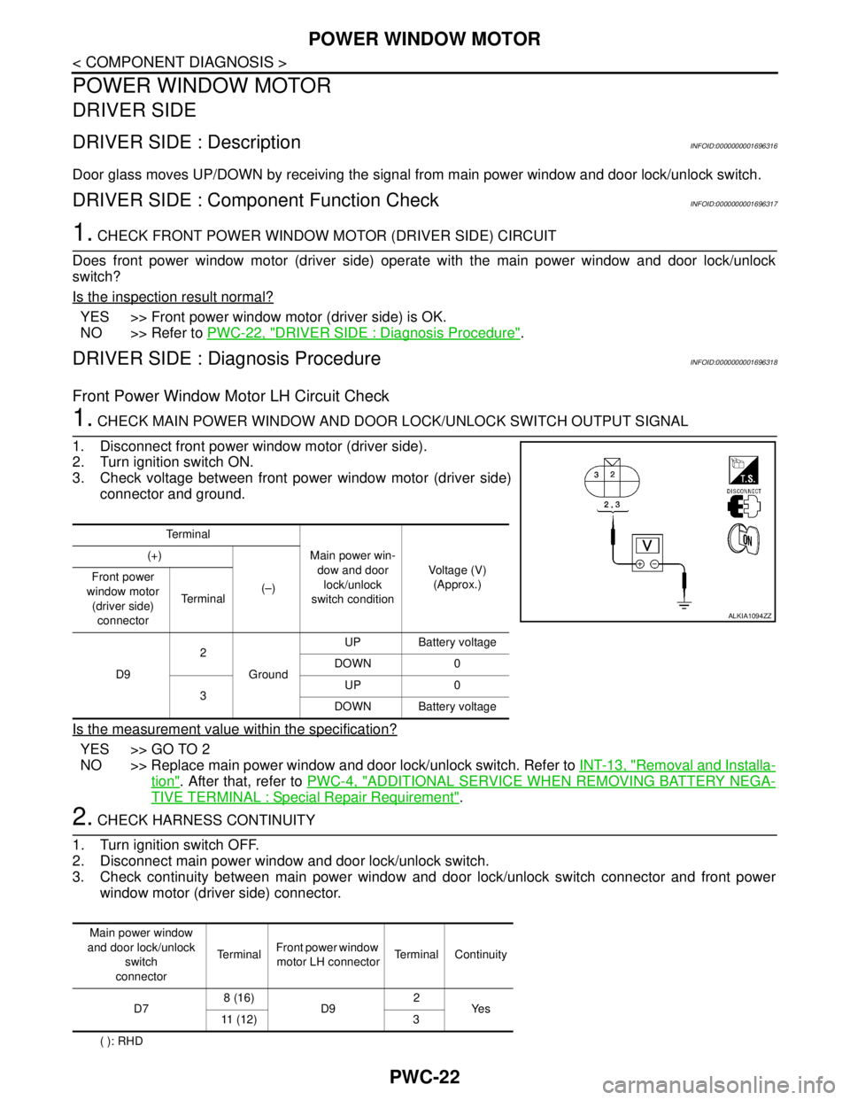
3. Check voltage between front power window motor (driver side)
connector and ground.
Is the measurement value within the specification?
YES >> GO TO 2
NO >> Replace main power window and door lock/unlock switch. Refer to INT-13, "
Removal and Installa-
tion". After that, refer to PWC-4, "ADDITIONAL SERVICE WHEN REMOVING BATTERY NEGA-
TIVE TERMINAL : Special Repair Requirement".
2. CHECK HARNESS CONTINUITY
1. Turn ignition switch OFF.
2. Disconnect main power window and door lock/unlock switch.
3. Check continuity between main power window and door lock/unlock switch connector and front power
window motor (driver side) connector.
( ): RHDTe r m i n a l
Main power win-
dow and door
lock/unlock
switch conditionVoltage (V)
(Approx.) (+)
(–) Front power
window motor
(driver side)
connectorTe r m i n a l
D92
GroundUP Battery voltage
DOWN 0
3UP 0
DOWN Battery voltage
ALKIA1094ZZ
Main power window
and door lock/unlock
switch
connectorTerminalFront power window
motor LH connectorTerminal Continuity
D78 (16)
D92
Ye s
11 ( 1 2 ) 3
Page 4484 of 5883
POWER WINDOW MOTOR
PWC-23
< COMPONENT DIAGNOSIS >
C
D
E
F
G
H
I
J
L
MA
B
PWC
N
O
P
4. Check continuity between main power window and door lock/unlock switch connector and ground.
( ): RHD
Is the inspection result normal?
YES >> GO TO 3
NO >> Repair or replace harness.
3. CHECK FRONT POWER WINDOW MOTOR (DRIVER SIDE)
Check front power window motor (driver side).
Refer to PWC-23, "
DRIVER SIDE : Component Inspection".
Is the inspection result normal?
YES >> Check intermittent incident. Refer to GI-55, "Intermittent Incident".
NO >> Replace front power window motor (driver side). Refer to GW-14, "
Removal and Installation".
After that, refer to PWC-4, "
ADDITIONAL SERVICE WHEN REMOVING BATTERY NEGATIVE
TERMINAL : Special Repair Requirement".
DRIVER SIDE : Component InspectionINFOID:0000000001696319
COMPONENT INSPECTION
1.CHECK FRONT POWER WINDOW MOTOR (DRIVER SIDE)
Does motor operate by connecting the battery voltage directly to power window motor?
Is the inspection result normal?
YES >> Front power window motor (driver side) is OK.
NO >> Replace front power window motor (driver side). Refer to GW-14, "
Removal and Installation".
After that, refer to PWC-4, "
ADDITIONAL SERVICE WHEN REMOVING BATTERY NEGATIVE
TERMINAL : Special Repair Requirement".
DRIVER SIDE : Special Repair RequirementINFOID:0000000001696320
1. PERFORM INITIALIZATION PROCEDURE
Perform initialization procedure.
Refer to PWC-4, "
ADDITIONAL SERVICE WHEN REMOVING BATTERY NEGATIVE TERMINAL : Special
Repair Requirement".
Is the inspection result normal?
YES >> GO TO 2
NO >> Check intermittent incident. Refer to GI-55, "
Intermittent Incident".
2. CHECK ANTI-PINCH OPERATION
Check anti-pinch operation.
Refer to PWC-4, "
ADDITIONAL SERVICE WHEN REMOVING BATTERY NEGATIVE TERMINAL : Special
Repair Requirement".
Is the inspection result normal?
YES >> Inspection End.
NO >> Refer to PWC-29, "
DRIVER SIDE : Component Function Check".
Main power window and
door lock/unlock switch
connectorTe r m i n a l
GroundContinuity
D78 (16)
No
11 ( 1 2 )
Te r m i n a l
Motor condition
(+) (–)
23 DOWN
32 UP
Page 4485 of 5883
PWC-24
< COMPONENT DIAGNOSIS >
POWER WINDOW MOTOR
PASSENGER SIDE
PASSENGER SIDE : DescriptionINFOID:0000000001696321
Door glass moves UP/DOWN by receiving the signal from main power window and door lock/unlock switch or
power window and door lock/unlock switch (passenger side).
PASSENGER SIDE : Component Function CheckINFOID:0000000001696322
1. CHECK FRONT POWER WINDOW MOTOR (PASSENGER SIDE) CIRCIUT
Does front power window motor (passenger side) operate with main power window and door lock/unlock
switch or power window and door lock/unlock switch?
Is the inspection result normal?
YES >> Front power window motor (passenger side) is OK.
NO >> Refer to PWC-24, "
PASSENGER SIDE : Diagnosis Procedure".
PASSENGER SIDE : Diagnosis ProcedureINFOID:0000000001696323
Front Power Window Motor (Passenger Side) Circuit Check
1. CHECK POWER WINDOW AND DOOR LOCK/UNLOCK SWITCH (PASSENGER SIDE) OUTPUT SIG-
NAL
1. Disconnect front power window motor (passenger side).
2. Turn ignition switch ON.
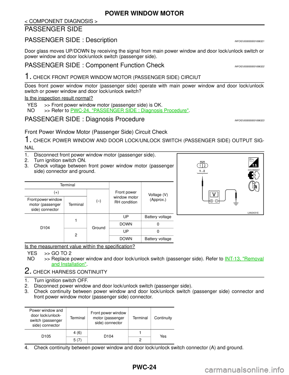
3. Check voltage between front power window motor (passenger
side) connector and ground.
Is the measurement value within the specification?
YES >> GO TO 2
NO >> Replace power window and door lock/unlock switch (passenger side). Refer to INT-13, "
Removal
and Installation".
2. CHECK HARNESS CONTINUITY
1. Turn ignition switch OFF.
2. Disconnect power window and door lock/unlock switch (passenger side).
3. Check continuity between power window and door lock/unlock switch (passenger side) connector and
front power window motor (passenger side) connector.
4. Check continuity between power window and door lock/unlock switch connector (A) and ground.
Te r m i n a l
Front power
window motor
RH conditionVoltage (V)
(Approx.) (+)
(–) Front power window
motor (passenger
side) connectorTe r m i n a l
D1041
GroundUP Battery voltage
DOWN 0
2UP 0
DOWN Battery voltage
LIIA2431E
Power window and
door lock/unlock-
switch (passenger
side) connectorTe r m i n a lFront power window
motor (passenger
side) connectorTerminal Continuity
D1054 (6)
D1041
Ye s
5 (7) 2