Page 9 of 56

TROUBLE DIAGNOSIS
SRS-9
C
D
E
F
G
I
J
K
L
MA
B
SRS
Revision: 2006 November2007 350Z
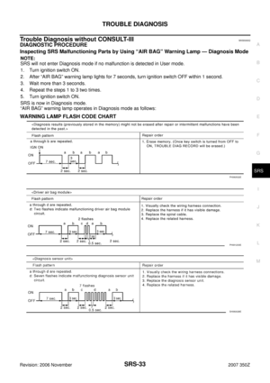
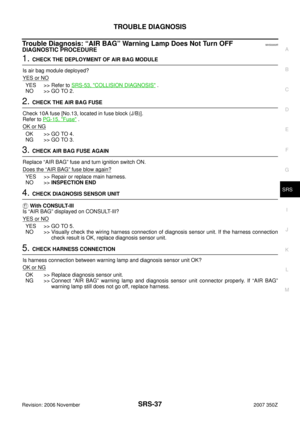
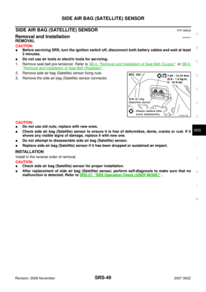
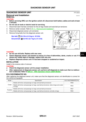
TROUBLE DIAGNOSISPFP:00004
Trouble Diagnosis IntroductionNHS0000H
CAUTION:
�Do not use electrical test equipment on any circuit related to the SRS unless instructed in this Ser-
vice Manual. SRS wiring harnesses can be identified by yellow and/or orange harnesses or har-
ness connectors.
�Do not repair, splice or modify the SRS wiring harness. If the harness is damaged, replace it with a
new one.
�Keep ground portion clean.
DIAGNOSIS FUNCTION
The SRS self-diagnostic results can be read by using “AIR BAG” warning lamp and/or CONSULT-lll.
The User mode is exclusively prepared for the customer (driver). This mode warns the driver of a system mal-
function through the operation of the “AIR BAG” warning lamp.
The Diagnosis mode allows the technician to locate and inspect the malfunctioning part.
The mode applications for the “AIR BAG” warning lamp and CONSULT-IlI are as follows:
HOW TO PERFORM TROUBLE DIAGNOSES FOR QUICK AND ACCURATE REPAIR
A good understanding of the malfunction conditions can make troubleshooting faster and more accurate.
In general, each customer feels differently about a malfunction. It is important to fully understand the symp-
toms or conditions for a customer complaint.
Information from Customer
WHAT..... Vehicle model
WHEN..... Date, Frequencies
WHERE..... Road conditions
HOW..... Operating conditions, Symptoms
Preliminary Check
Make sure that the following parts are in good order.
�Battery (Refer to SC-4, "How to Handle Battery" .)
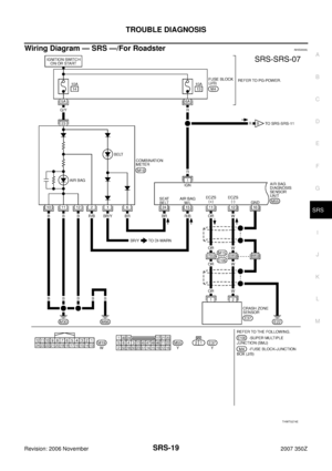
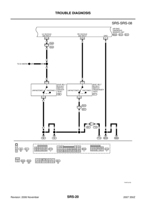
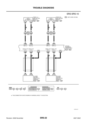
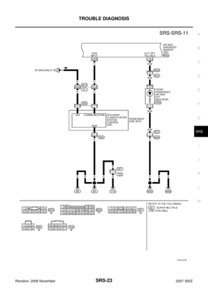
�Fuse (Refer to SRS-13, "Wiring Diagram — SRS —/For Coupe" or SRS-19, "Wiring Diagram — SRS —/
For Roadster" .)
�System component-to-harness connections
User mode Diagnosis mode Display type
“AIR BAG” warning lamp X X ON-OFF operation
CONSULT-lII — X Monitoring
Page 10 of 56
SRS-10
TROUBLE DIAGNOSIS
Revision: 2006 November2007 350Z
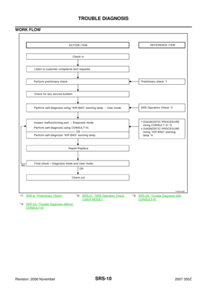
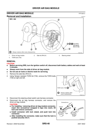
WORK FLOW
*1:SRS-9, "Preliminary Check".*2:SRS-27, "SRS Operation Check
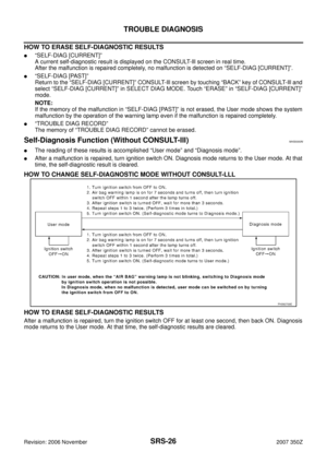
(USER MODE)".*3:SRS-29, "
Trouble Diagnosis with
CONSULT-IlI".
*4:SRS-33, "
Trouble Diagnosis without
CONSULT-IlI".
PHIA1363E
Page 11 of 56
TROUBLE DIAGNOSIS
SRS-11
C
D
E
F
G
I
J
K
L
MA
B
SRS
Revision: 2006 November2007 350Z
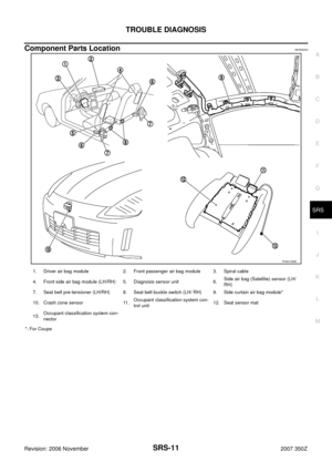
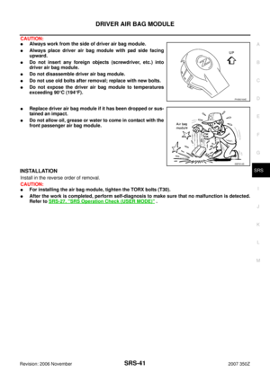
Component Parts LocationNHS0000I
*: For Coupe
PHIA1356E
1. Driver air bag module 2. Front passenger air bag module 3. Spiral cable
4. Front side air bag module (LH/RH) 5. Diagnosis sensor unit 6.Side air bag (Satellite) sensor (LH/
RH)
7. Seat belt pre-tensioner (LH/RH) 8. Seat belt buckle switch (LH/ RH) 9. Side curtain air bag module*
10. Crash zone sensor 11.Occupant classification system con-
trol unit12. Seat sensor mat
13.Occupant classification system con-
nector
Page 12 of 56
SRS-12
TROUBLE DIAGNOSIS
Revision: 2006 November2007 350Z
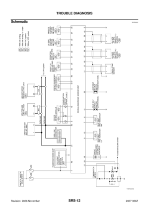
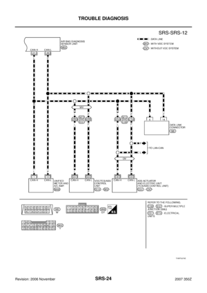
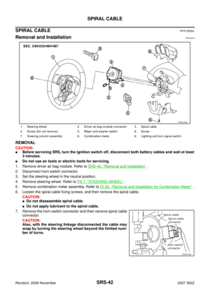
SchematicNHS0000J
THWT0270E
Page 13 of 56
TROUBLE DIAGNOSIS
SRS-13
C
D
E
F
G
I
J
K
L
MA
B
SRS
Revision: 2006 November2007 350Z
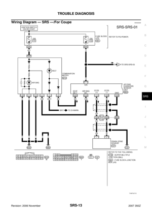
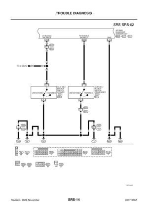
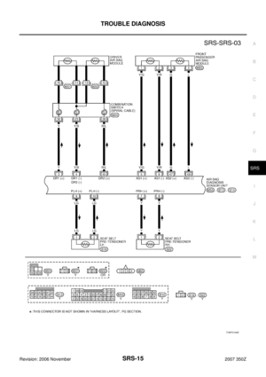
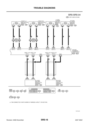
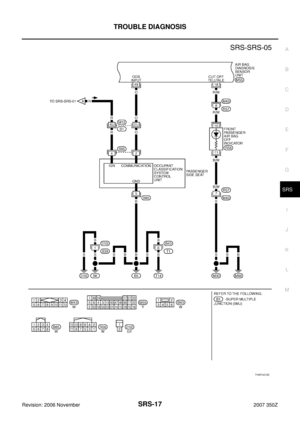
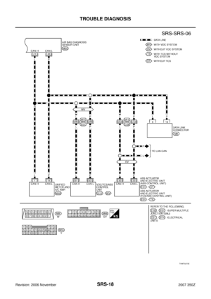
Wiring Diagram — SRS —/For CoupeNHS0000K
THWT0271E
Page 14 of 56
SRS-14
TROUBLE DIAGNOSIS
Revision: 2006 November2007 350Z
THWT0258E
Page 15 of 56
TROUBLE DIAGNOSIS
SRS-15
C
D
E
F
G
I
J
K
L
MA
B
SRS
Revision: 2006 November2007 350Z
THWT0165E
Page 16 of 56
SRS-16
TROUBLE DIAGNOSIS
Revision: 2006 November2007 350Z
THWT0259E


\".*3:SRS-29, \"
Trouble Diagnosis with
CONSULT-IlI\".
*4:SR")


