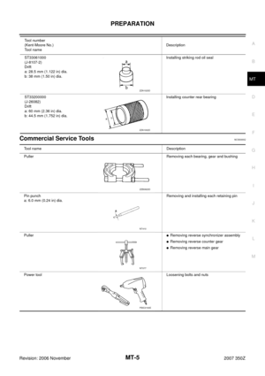
Page 17 of 62
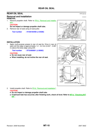
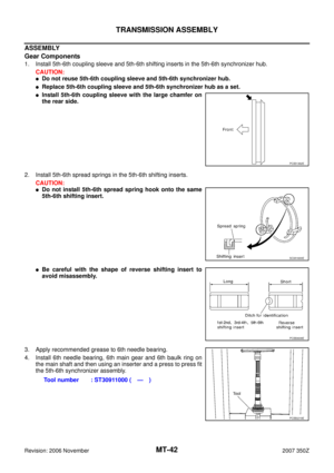
AIR BREATHER HOSE
MT-17
D
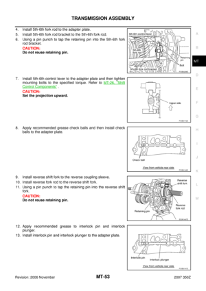
E
F
G
H
I
J
K
L
MA
B
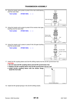
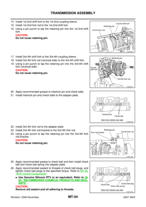
MT
Revision: 2006 November2007 350Z
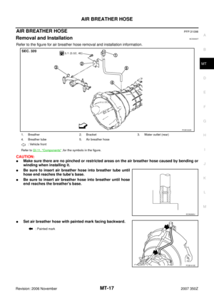
AIR BREATHER HOSEPFP:31098
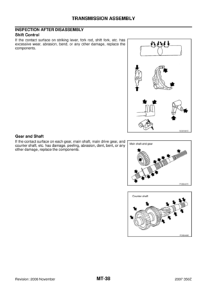
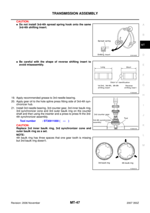
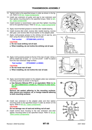
Removal and InstallationNCS0000Y
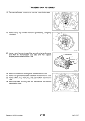
Refer to the figure for air breather hose removal and installation information.
CAUTION:
�Make sure there are no pinched or restricted areas on the air breather hose caused by bending or
winding when installing it.
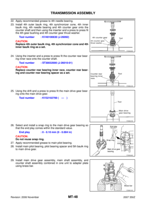
�Be sure to insert air breather hose into breather tube until
hose end reaches the tube's base.
�Be sure to insert air breather hose into breather until hose
end reaches the breather's base.
�Set air breather hose with painted mark facing backward.
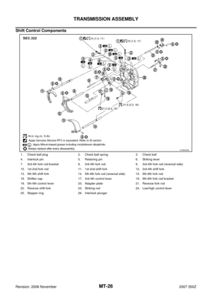
1. Breather 2. Bracket 3. Water outlet (rear)
4. Breather tube 5. Air breather hose
: Vehicle front
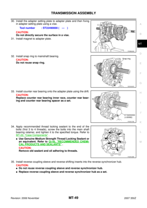
Refer to GI-11, "
Components" ,for the symbols in the figure.
PCIB1933E
SCIA2663J
: Painted mark
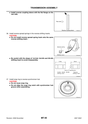
PCIB1913E
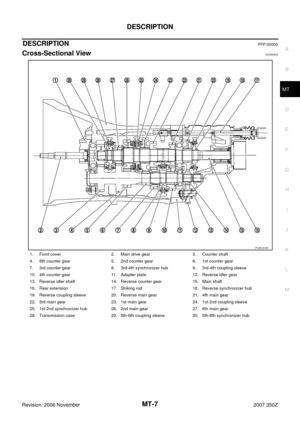
Page 18 of 62

MT-18
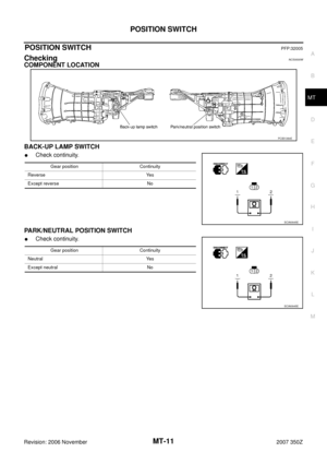
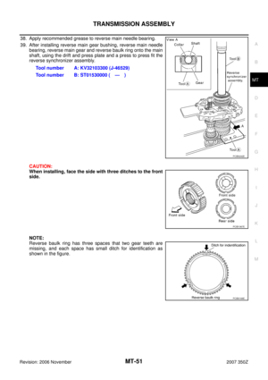
TRANSMISSION ASSEMBLY
Revision: 2006 November2007 350Z
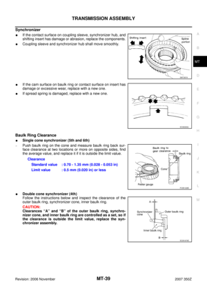
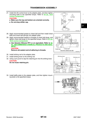
TRANSMISSION ASSEMBLYPFP:32010
Removal and InstallationNCS0000Z
CAUTION:
If transmission assembly is removed from the Vehicle, always replace CSC (Concentric Slave Cylin-
der) body and CSC tube. Return CSC body insert to original position to remove transmission assem-
bly. Dust on clutch disc sliding parts may damage seal of CSC body and may cause clutch fluid
leakage.
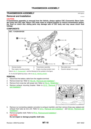
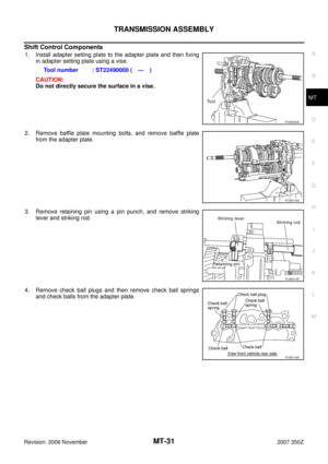
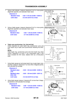
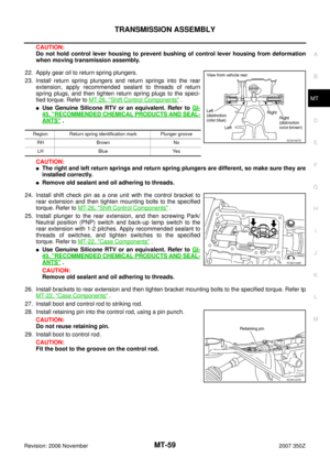
COMPONENTS
REMOVAL
1. Disconnect the battery cable from the negative terminal.
2. Remove tower bar. Refer to FSU-20, "
Removal and Installation" .
3. Remove front cross bar with power tool. Refer to FSU-9, "
REMOVAL" .
4. Remove exhaust mounting bracket. Refer to EX-3, "
Removal
and Installation" .
5. Remove nut connecting catalytic converter to exhaust manifold, and then remove three way catalyst and
exhaust front tube as one unit. Refer to EX-3, "
Removal and Installation" and EM-22, "Removal and
Installation" .
6. Remove propeller shaft. Refer to PR-6, "
Removal and Installation" .
CAUTION:
Do not impact or damage propeller shaft tube.
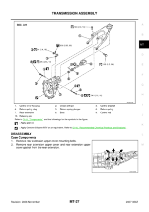
1. Harness bracket 2. Transmission assembly 3. Rear plate cover
4. Rear engine mounting member 5. Engine mounting insulator (rear) 6. Dynamic damper (For coupe)
Refer to GI-11, "
Components" and the following for the symbols in the figure.
: For the bolt tightening torque, refer to MT-20, "
INSTALLATION" .
PCIB1942E
SCIA1471E
Page 19 of 62
TRANSMISSION ASSEMBLY
MT-19
D
E
F
G
H
I
J
K
L
MA
B
MT
Revision: 2006 November2007 350Z
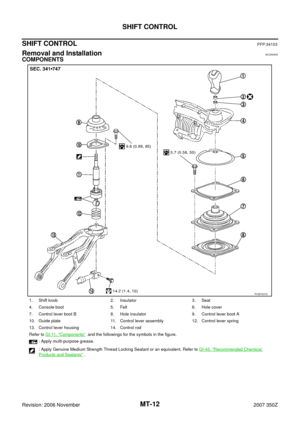
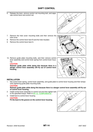
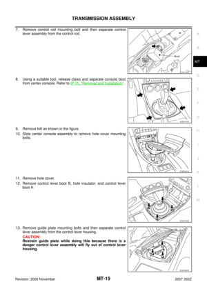
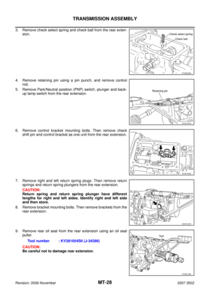
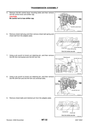
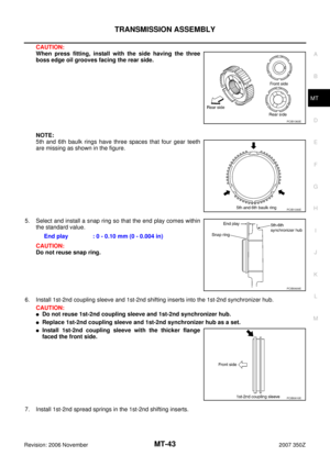
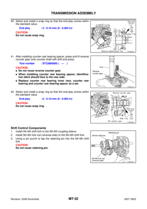
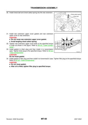
7. Remove control rod mounting bolt and then separate control
lever assembly from the control rod.
8. Using a suitable tool, release claws and separate console boot
from center console. Refer to IP-11, "
Removal and Installation" .
9. Remove felt as shown in the figure.
10. Slide center console assembly to remove hole cover mounting
bolts.
11. Remove hole cover.
12. Remove control lever boot B, hole insulator, and control lever
boot A.
13. Remove guide plate mounting bolts and then separate control
lever assembly from the control lever housing.
CAUTION:
Restrain guide plate while doing this because there is a
danger control lever assembly will fly out of control lever
housing.
SCIA1364E
SCIA1473E
PCIB1941E
SCIA1590E
SCIA1591E
Page 20 of 62
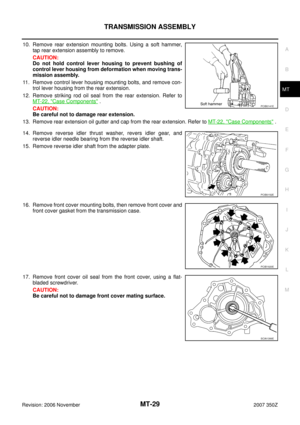
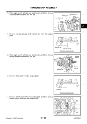
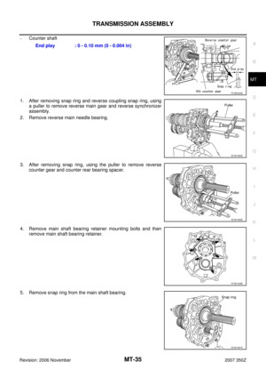
, clutch hose (2), and lock plate (3).
Refer to CL-15, \"
Removal and Installation\" .
CAUTION:
�Keep painted surfa")
MT-20
TRANSMISSION ASSEMBLY
Revision: 2006 November2007 350Z
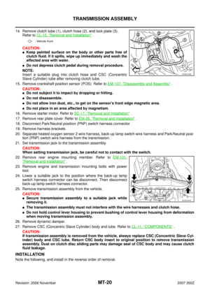
14. Remove clutch tube (1), clutch hose (2), and lock plate (3).
Refer to CL-15, "
Removal and Installation" .
CAUTION:
�Keep painted surface on the body or other parts free of
clutch fluid. If it spills, wipe up immediately and wash the
affected area with water.
�Do not depress clutch pedal during removal procedure.
NOTE:
Insert a suitable plug into clutch hose and CSC (Concentric
Slave Cylinder) tube after removing clutch tube.
15. Remove crankshaft position sensor (POS). Refer to EM-107, "
Disassembly and Assembly" .
CAUTION:
�Do not subject it to impact by dropping or hitting.
�Do not disassemble.
�Do not allow iron dust, etc., to get on the sensor's front edge magnetic area.
�Do not place in an area affected by magnetism.
16. Remove starter motor. Refer to SC-17, "
Removal and Installation" .
17. Remove rear plate cover. Refer to EM-26, "
Removal and Installation" .
18. Disconnect Park/Neutral position (PNP) switch harness connector.
19. Remove harness brackets.
20. Separate heated oxygen sensor 2 wire harness, back-up lamp switch wire harness and Park/Neutral posi-
tion (PNP) switch wire harness from the transmission.
21. Set transmission jack to the transmission assembly.
CAUTION:
When setting transmission jack, be careful not to contact with the switch.
22. Remove rear engine mounting member. Refer to EM-101,
"Removal and Installation" .
23. Remove engine and transmission mounting bolts with power
tool.
24. Lower a suitable jack to the position where the back-up lamp
switch harness connector can be disconnect. Then disconnect
back-up lamp switch harness connector.
25. Remove transmission assembly from the vehicle.
CAUTION:
�Secure transmission assembly to a suitable jack while
removing it.
�The transmission assembly must not interfere with the wire harnesses and clutch hose.
�Do not hold control lever housing to prevent bushing of control lever housing from deformation
when moving transmission assembly.
26. Remove dynamic damper.
27. Remove CSC (Concentric Slave Cylinder) body and tube. Refer to CL-11, "
COMPONENTS" .
CAUTION:
If transmission assembly is removed from the vehicle, always replace CSC (Concentric Slave Cyl-
inder) body and CSC tube. Return CSC body insert to original position to remove transmission
assembly. Dust on clutch disc sliding parts may damage seal of CSC body and may cause clutch
fluid leakage.
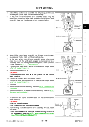
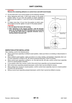
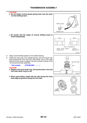
INSTALLATION
Note the following, and install in the reverse order of removal.
: Vehicle front
PCIB1915E
SCIA1531E
Page 21 of 62

TRANSMISSION ASSEMBLY
MT-21
D
E
F
G
H
I
J
K
L
MA
B
MT
Revision: 2006 November2007 350Z
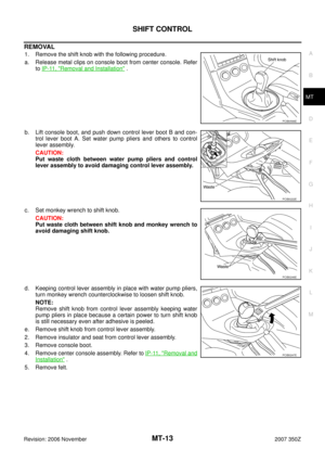
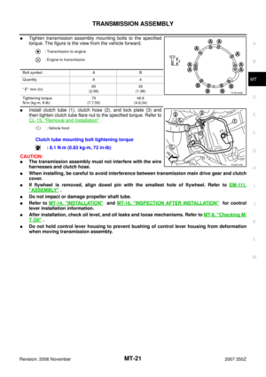
�Tighten transmission assembly mounting bolts to the specified
torque. The figure is the view from the vehicle forward.
�Install clutch tube (1), clutch hose (2), and lock plate (3) and
then tighten clutch tube flare nut to the specified torque. Refer to
CL-15, "
Removal and Installation" .
CAUTION:
�The transmission assembly must not interfere with the wire
harnesses and clutch hose.
�When installing, be careful to avoid interference between transmission main drive gear and clutch
cover.
�If flywheel is removed, align dowel pin with the smallest hole of flywheel. Refer to EM-111,
"ASSEMBLY" .
�Do not impact or damage propeller shaft tube.
�Refer to MT-14, "INSTALLATION" and MT-16, "INSPECTION AFTER INSTALLATION" for control
lever installation information.
�After installation, check oil level, and oil leaks and loose mechanisms. Refer to MT-9, "Checking M/
T Oil" .
�Do not hold control lever housing to prevent bushing of control lever housing from deformation
when moving transmission assembly.
: Transmission to engine
: Engine to transmission
Bolt symbol A B
Quantity 8 4
“” mm (in)65
(2.56)35
(1.38)
Tightening torque
N·m (kg-m, ft-lb)75
(7.7,55)46.6
(4.8,34)
: Vehicle front
Clutch tube mounting bolt tightening torque
: 8.1 N·m (0.83 kg-m, 72 in-lb)
PCIB1946E
PCIB1915E
Page 22 of 62
MT-22
TRANSMISSION ASSEMBLY
Revision: 2006 November2007 350Z
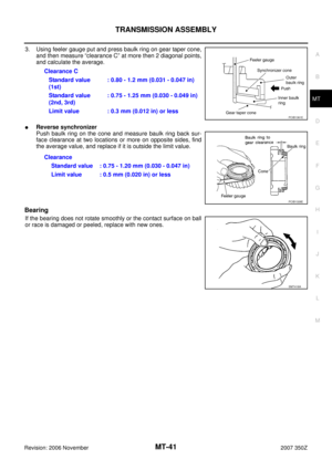
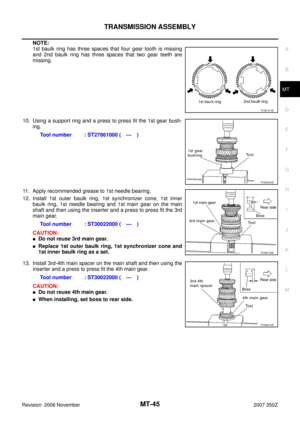
Disassembly and AssemblyNCS00011
COMPONENTS
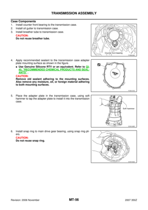
Case Components
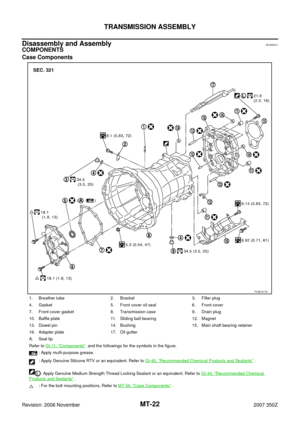
1. Breather tube 2. Bracket 3. Filler plug
4. Gasket 5. Front cover oil seal 6. Front cover
7. Front cover gasket 8. Transmission case 9. Drain plug
10. Baffle plate 11. Sliding ball bearing 12. Magnet
13. Dowel pin 14. Bushing 15. Main shaft bearing retainer
16. Adapter plate 17. Oil gutter
A. Seal lip
Refer to GI-11, "
Components" and the followings for the symbols in the figure.
: Apply multi-purpose grease.
: Apply Genuine Silicone RTV or an equivalent. Refer to GI-45, "
Recommended Chemical Products and Sealants" .
: Apply Genuine Medium Strength Thread Locking Sealant or an equivalent. Refer to GI-45, "
Recommended Chemical
Products and Sealants" .
: For the bolt mounting positions, Refer to MT-56, "
Case Components" .
PCIB1917E
Page 23 of 62
TRANSMISSION ASSEMBLY
MT-23
D
E
F
G
H
I
J
K
L
MA
B
MT
Revision: 2006 November2007 350Z
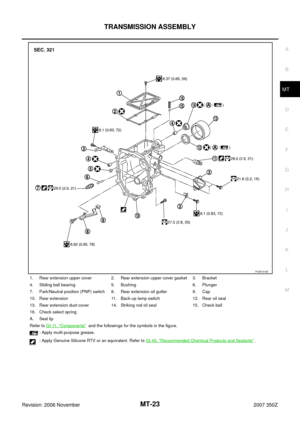
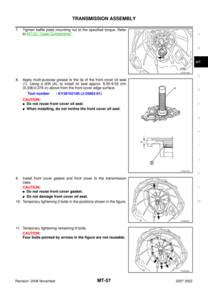
1. Rear extension upper cover 2. Rear extension upper cover gasket 3. Bracket
4. Sliding ball bearing 5. Bushing 6. Plunger
7. Park/Neutral position (PNP) switch 8. Rear extension oil gutter 9. Cap
10. Rear extension 11. Back-up lamp switch 12. Rear oil seal
13. Rear extension dust cover 14. Striking rod oil seal 15. Check ball
16. Check select spring
A. Seal lip
Refer to GI-11, "
Components" and the followings for the symbols in the figure.
: Apply multi-purpose grease.
: Apply Genuine Silicone RTV or an equivalent. Refer to GI-45, "
Recommended Chemical Products and Sealants" .
PCIB1918E
Page 24 of 62

MT-24
TRANSMISSION ASSEMBLY
Revision: 2006 November2007 350Z
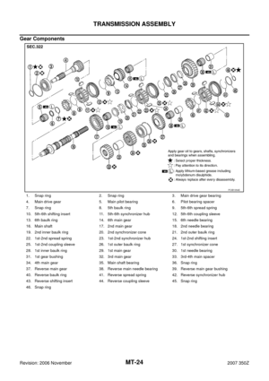
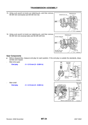
Gear Components
1. Snap ring 2. Snap ring 3. Main drive gear bearing
4. Main drive gear 5. Main pilot bearing 6. Pilot bearing spacer
7. Snap ring 8. 5th baulk ring 9. 5th-6th spread spring
10. 5th-6th shifting insert 11. 5th-6th synchronizer hub 12. 5th-6th coupling sleeve
13. 6th baulk ring 14. 6th main gear 15. 6th needle bearing
16. Main shaft 17. 2nd main gear 18. 2nd needle bearing
19. 2nd inner baulk ring 20. 2nd synchronizer cone 21. 2nd outer baulk ring
22. 1st-2nd spread spring 23. 1st-2nd synchronizer hub 24. 1st-2nd shifting insert
25. 1st-2nd coupling sleeve 26. 1st outer baulk ring 27. 1st synchronizer cone
28. 1st inner baulk ring 29. 1st main gear 30. 1st needle bearing
31. 1st gear bushing 32. 3rd main gear 33. 3rd-4th main spacer
34. 4th main gear 35. Main shaft bearing 36. Snap ring
37. Reverse main gear 38. Reverse main needle bearing 39. Reverse main gear bushing
40. Reverse baulk ring 41. Reverse spread spring 42. Reverse synchronizer hub
43. Reverse shifting insert 44. Reverse coupling sleeve 45. Snap ring
46. Snap ring
PCIB1354E