Page 25 of 62
TRANSMISSION ASSEMBLY
MT-25
D
E
F
G
H
I
J
K
L
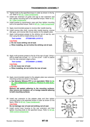
MA
B
MT
Revision: 2006 November2007 350Z
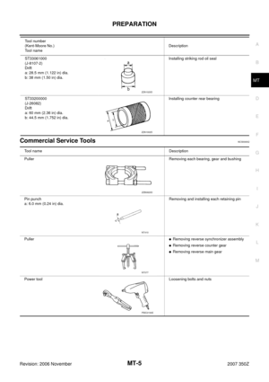
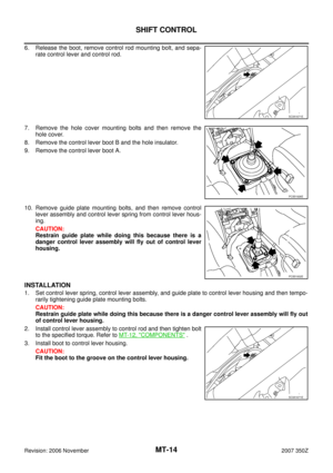
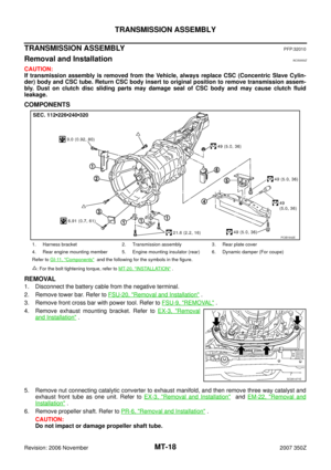
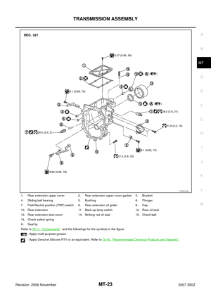
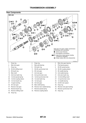
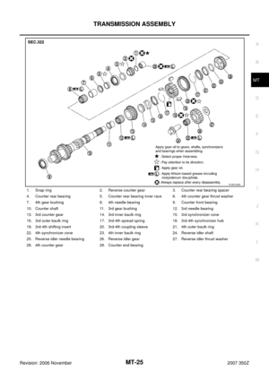
1. Snap ring 2. Reverse counter gear 3. Counter rear bearing spacer
4. Counter rear bearing 5. Counter rear bearing inner race 6. 4th counter gear thrust washer
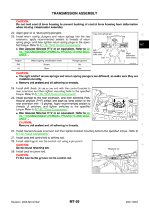
7. 4th gear bushing 8. 4th needle bearing 9. Counter front bearing
10. Counter shaft 11. 3rd gear bushing 12. 3rd needle bearing
13. 3rd counter gear 14. 3rd inner baulk ring 15. 3rd synchronizer cone
16. 3rd outer baulk ring 17. 3rd-4th spread spring 18. 3rd-4th synchronizer hub
19. 3rd-4th shifting insert 20. 3rd-4th coupling sleeve 21. 4th outer baulk ring
22. 4th synchronizer cone 23. 4th inner baulk ring 24. Reverse idler shaft
25. Reverse idler needle bearing 26. Reverse idler gear 27. Reverse idler thrust washer
28. 4th counter gear 29. Counter end bearing
PCIB1355E
Page 26 of 62
MT-26
TRANSMISSION ASSEMBLY
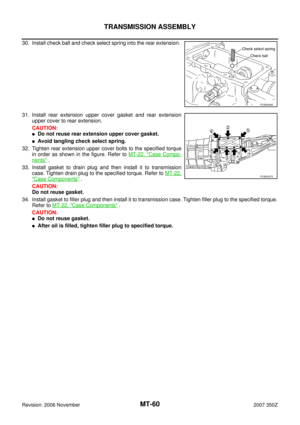
Revision: 2006 November2007 350Z
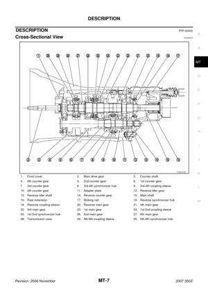
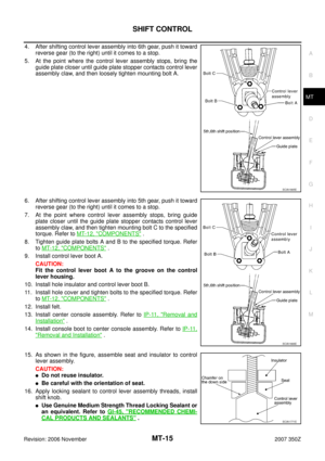
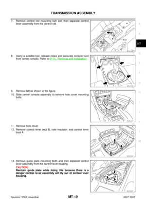
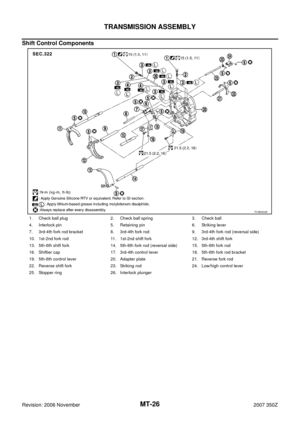
Shift Control Components
1. Check ball plug 2. Check ball spring 3. Check ball
4. Interlock pin 5. Retaining pin 6. Striking lever
7. 3rd-4th fork rod bracket 8. 3rd-4th fork rod 9. 3rd-4th fork rod (reversal side)
10. 1st-2nd fork rod 11. 1st-2nd shift fork 12. 3rd-4th shift fork
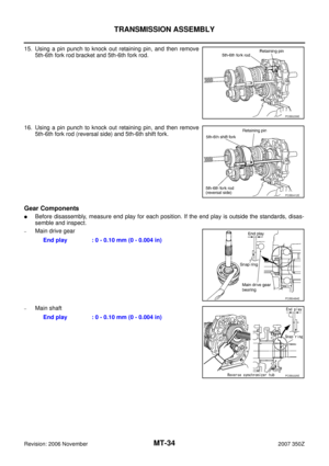
13. 5th-6th shift fork 14. 5th-6th fork rod (reversal side) 15. 5th-6th fork rod
16. Shiftier cap 17. 3rd-4th control lever 18. 5th-6th fork rod bracket
19. 5th-6th control lever 20. Adapter plate 21. Reverse fork rod
22. Reverse shift fork 23. Striking rod 24. Low/high control lever
25. Stopper ring 26. Interlock plunger
PCIB0902E
Page 27 of 62
TRANSMISSION ASSEMBLY
MT-27
D
E
F
G
H
I
J
K
L
MA
B
MT
Revision: 2006 November2007 350Z
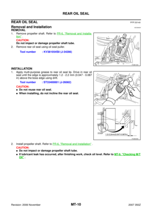
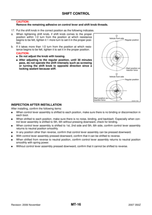
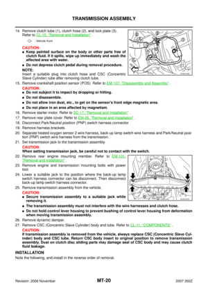
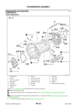
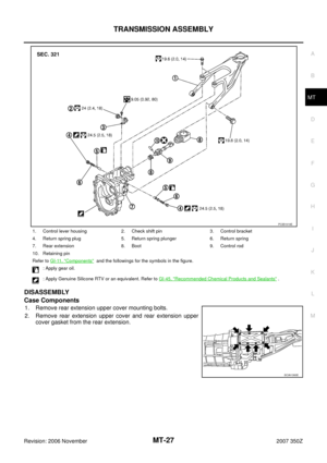
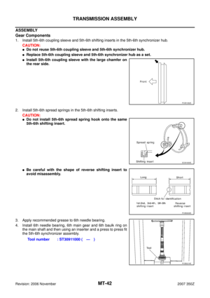
DISASSEMBLY
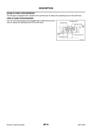
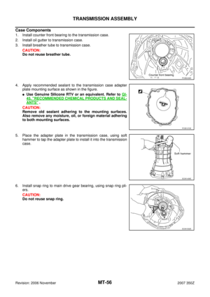
Case Components
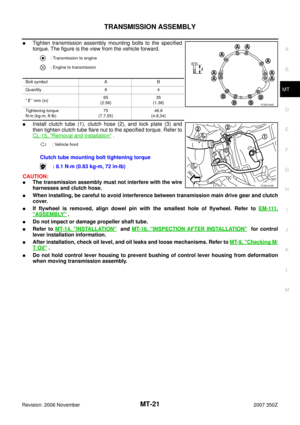
1. Remove rear extension upper cover mounting bolts.
2. Remove rear extension upper cover and rear extension upper
cover gasket from the rear extension.
1. Control lever housing 2. Check shift pin 3. Control bracket
4. Return spring plug 5. Return spring plunger 6. Return spring
7. Rear extension 8. Boot 9. Control rod
10. Retaining pin
Refer to GI-11, "
Components" and the followings for the symbols in the figure.
: Apply gear oil.
: Apply Genuine Silicone RTV or an equivalent. Refer to GI-45, "
Recommended Chemical Products and Sealants" .
PCIB1919E
SCIA1393E
Page 28 of 62
MT-28
TRANSMISSION ASSEMBLY
Revision: 2006 November2007 350Z
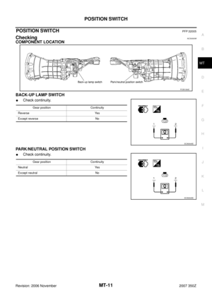
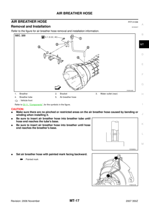
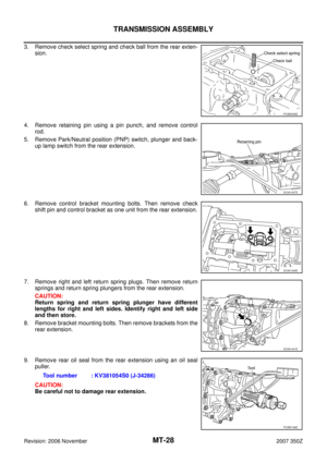
3. Remove check select spring and check ball from the rear exten-
sion.
4. Remove retaining pin using a pin punch, and remove control
rod.
5. Remove Park/Neutral position (PNP) switch, plunger and back-
up lamp switch from the rear extension.
6. Remove control bracket mounting bolts. Then remove check
shift pin and control bracket as one unit from the rear extension.
7. Remove right and left return spring plugs. Then remove return
springs and return spring plungers from the rear extension.
CAUTION:
Return spring and return spring plunger have different
lengths for right and left sides. Identify right and left side
and then store.
8. Remove bracket mounting bolts. Then remove brackets from the
rear extension.
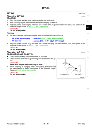
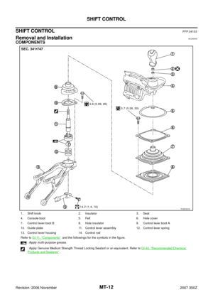
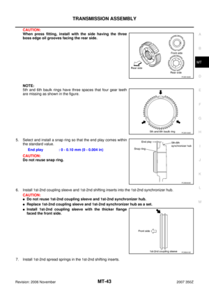
9. Remove rear oil seal from the rear extension using an oil seal
puller.
CAUTION:
Be careful not to damage rear extension.
PCIB0599E
SCIA1437E
SCIA1440E
SCIA1441E
Tool number : KV381054S0 (J-34286)
PCIB0196E
Page 29 of 62

TRANSMISSION ASSEMBLY
MT-29
D
E
F
G
H
I
J
K
L
MA
B
MT
Revision: 2006 November2007 350Z
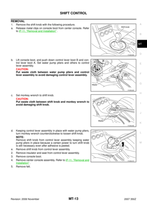
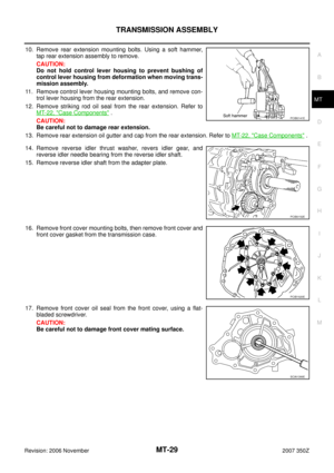
10. Remove rear extension mounting bolts. Using a soft hammer,
tap rear extension assembly to remove.
CAUTION:
Do not hold control lever housing to prevent bushing of
control lever housing from deformation when moving trans-
mission assembly.
11. Remove control lever housing mounting bolts, and remove con-
trol lever housing from the rear extension.
12. Remove striking rod oil seal from the rear extension. Refer to
MT-22, "
Case Components" .
CAUTION:
Be careful not to damage rear extension.
13. Remove rear extension oil gutter and cap from the rear extension. Refer to MT-22, "
Case Components" .
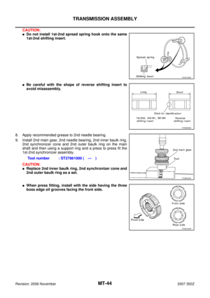
14. Remove reverse idler thrust washer, revers idler gear, and
reverse idler needle bearing from the reverse idler shaft.
15. Remove reverse idler shaft from the adapter plate.
16. Remove front cover mounting bolts, then remove front cover and
front cover gasket from the transmission case.
17. Remove front cover oil seal from the front cover, using a flat-
bladed screwdriver.
CAUTION:
Be careful not to damage front cover mating surface.
PCIB0141E
PCIB0152E
PCIB1920E
SCIA1399E
Page 30 of 62
MT-30
TRANSMISSION ASSEMBLY
Revision: 2006 November2007 350Z
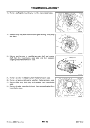
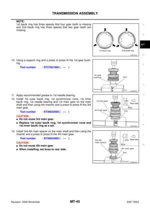
18. Remove baffle plate mounting nut from the transmission case.
19. Remove snap ring from the main drive gear bearing, using snap
ring pliers.
20. Using a soft hammer to carefully tap main shaft and counter
shaft from the transmission case side, and then separate
adapter plate and transmission case.
21. Remove counter front bearing from the transmission case.
22. Remove oil gutter and breather tube from the transmission case.
23. Remove filler plug, drain plug, and gaskets from transmission
case.
24. Remove bracket mounting bolt and then remove bracket from
transmission case.
SCIA1443E
SCIA1532E
SCIA1687E
PCIB0436E
Page 31 of 62
TRANSMISSION ASSEMBLY
MT-31
D
E
F
G
H
I
J
K
L
MA
B
MT
Revision: 2006 November2007 350Z
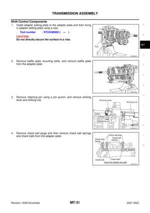
Shift Control Components
1. Install adapter setting plate to the adapter plate and then fixing
in adapter setting plate using a vise.
CAUTION:
Do not directly secure the surface in a vise.
2. Remove baffle plate mounting bolts, and remove baffle plate
from the adapter plate.
3. Remove retaining pin using a pin punch, and remove striking
lever and striking rod.
4. Remove check ball plugs and then remove check ball springs
and check balls from the adapter plate.Tool number : ST22490000 ( — )
PCIB0254E
PCIB0154E
PCIB0414E
PCIB0143E
Page 32 of 62
MT-32
TRANSMISSION ASSEMBLY
Revision: 2006 November2007 350Z
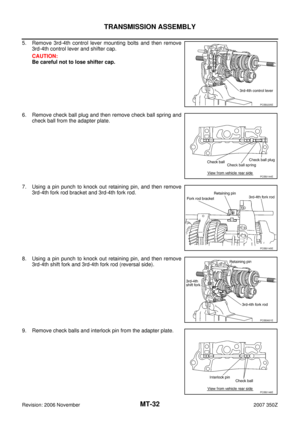
5. Remove 3rd-4th control lever mounting bolts and then remove
3rd-4th control lever and shifter cap.
CAUTION:
Be careful not to lose shifter cap.
6. Remove check ball plug and then remove check ball spring and
check ball from the adapter plate.
7. Using a pin punch to knock out retaining pin, and then remove
3rd-4th fork rod bracket and 3rd-4th fork rod.
8. Using a pin punch to knock out retaining pin, and then remove
3rd-4th shift fork and 3rd-4th fork rod (reversal side).
9. Remove check balls and interlock pin from the adapter plate.
PCIB0235E
PCIB0144E
PCIB0145E
PCIB0601E
PCIB0146E