Page 9 of 62

M/T OIL
MT-9
D
E
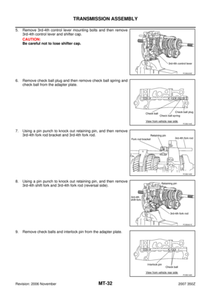
F
G
H
I
J
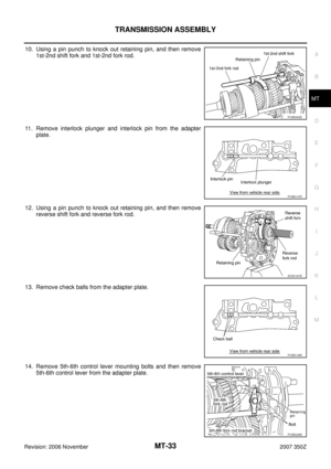
K
L
MA
B
MT
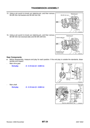
Revision: 2006 November2007 350Z
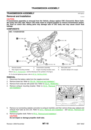
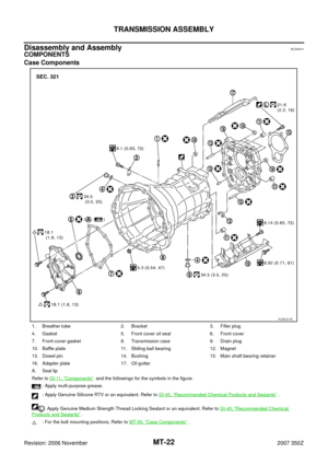
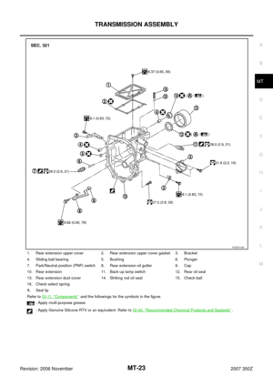
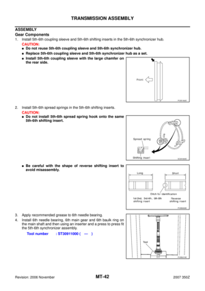
M/T OILPFP:KLD20
Changing M/T OilNCS0000T
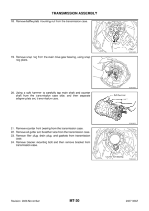
DRAINING
1. Start the engine and warm up the transmission unit sufficiently.
2. After stopping engine, remove filler plug and drain plug to drain oil.
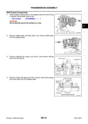
3. Replace gasket on drain plug with new one. Screw drain plug into transmission case, and tighten to the
specified torque. Refer to MT-22, "
Case Components" .
CAUTION:
Do not reuse gasket.
FILLING
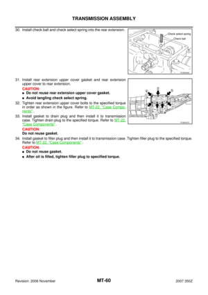
1. Fill new oil into the transmission to the level of the filler plug mounting hole.
2. Replace gasket on filler plug with new one. Screw filler plug into transmission case, and tighten to the
specified torque. Refer to MT-22, "
Case Components" .
CAUTION:
Do not reuse gasket.
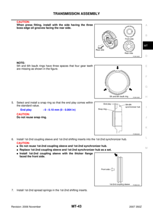
Checking M/T OilNCS0000U
OIL LEAKAGE AND OIL LEVEL
�Check if oil is leaking from transmission or around it.
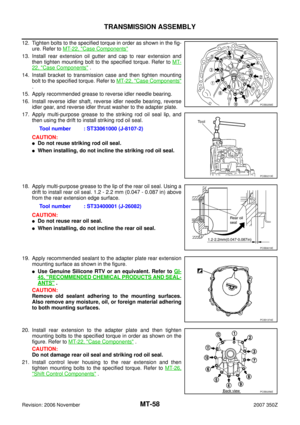
�Check oil level from filler plug mounting hole as shown in the fig-
ure.
CAUTION:
Never start engine while checking oil level.
�When screwing in filler plug with a new gasket, first screw into
the transmission by hand, then tighten to the specified torque.
Refer to MT-22, "
Case Components" .
CAUTION:
Do not reuse gasket.Oil grade and viscosity : Refer to MA-11, "
Fluids and Lubricants" .
Oil capacity
: Approx. 2.93 (6-1/4 US pt, 5-1/8 lmp pt)
PCIB0268E
Page 10 of 62
MT-10
REAR OIL SEAL
Revision: 2006 November2007 350Z
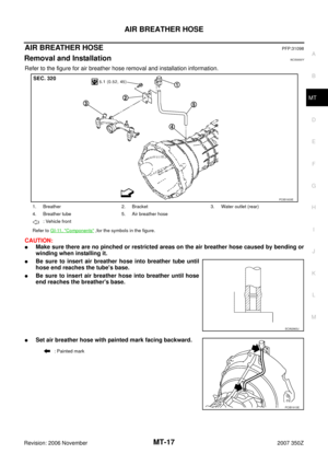
REAR OIL SEALPFP:33140
Removal and InstallationNCS0000V
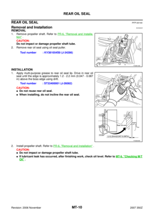
REMOVAL
1. Remove propeller shaft. Refer to PR-6, "Removal and Installa-
tion" .
CAUTION:
Do not impact or damage propeller shaft tube.
2. Remove rear oil seal using oil seal puller.
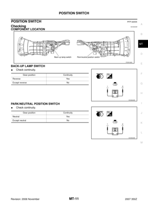
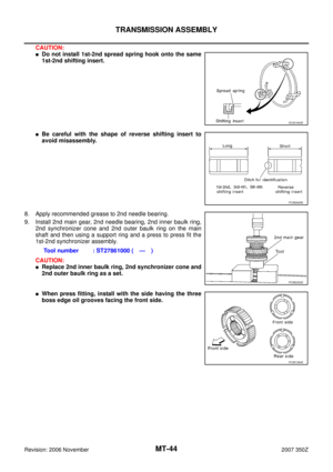
INSTALLATION
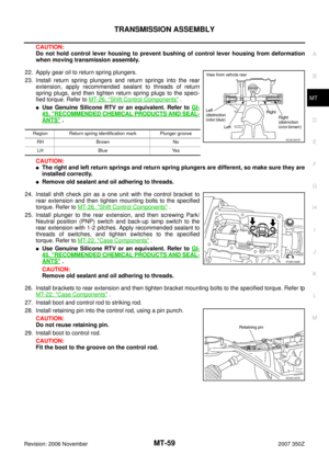
1. Apply multi-purpose grease to rear oil seal lip. Drive in rear oil
seal until the edge is approximately 1.2 - 2.2 mm (0.047 - 0.087
in) above the boss edge using drift.
CAUTION:
�Do not reuse rear oil seal.
�When installing, do not incline the rear oil seal.
2. Install propeller shaft. Refer to PR-6, "
Removal and Installation" .
CAUTION:
�Do not impact or damage propeller shaft tube.
�If lubricant leak has occurred, after finishing work, check oil level. Refer to MT-9, "Checking M/T
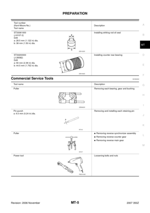
Oil" . Tool number : KV381054S0 (J-34286)
PCIB0194E
Tool number : ST33400001 (J-26082)
PCIB0595E
Page 11 of 62
POSITION SWITCH
MT-11
D
E
F
G
H
I
J
K
L
MA
B
MT
Revision: 2006 November2007 350Z
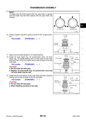
POSITION SWITCHPFP:32005
CheckingNCS0000W
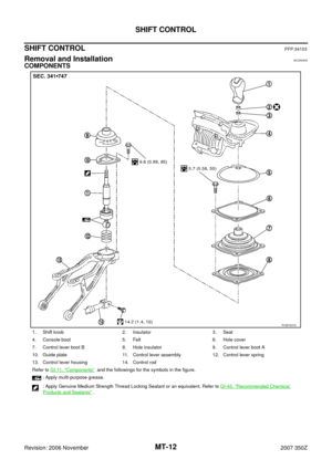
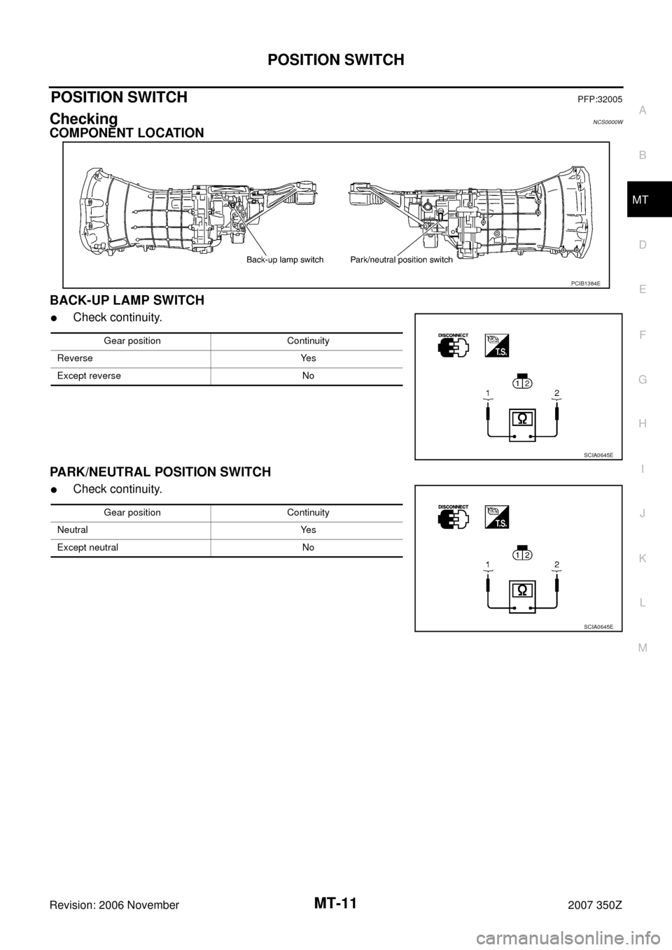
COMPONENT LOCATION
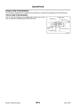
BACK-UP LAMP SWITCH
�Check continuity.
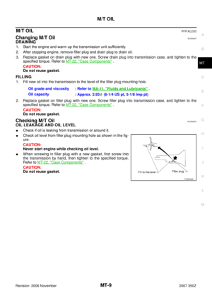
PARK/NEUTRAL POSITION SWITCH
�Check continuity.
PCIB1384E
Gear position Continuity
Reverse Yes
Except reverse No
SCIA0645E
Gear position Continuity
Neutral Yes
Except neutral No
SCIA0645E
Page 12 of 62
MT-12
SHIFT CONTROL
Revision: 2006 November2007 350Z
SHIFT CONTROLPFP:34103
Removal and InstallationNCS0000X
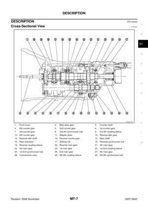
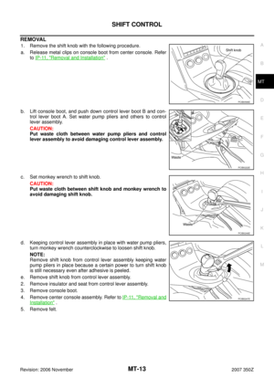
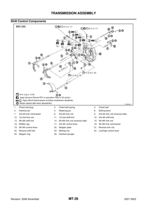
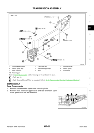
COMPONENTS
1. Shift knob 2. Insulator 3. Seat
4. Console boot 5. Felt 6. Hole cover
7. Control lever boot B 8. Hole insulator 9. Control lever boot A
10. Guide plate 11. Control lever assembly 12. Control lever spring
13. Control lever housing 14. Control rod
Refer to GI-11, "
Components" and the followings for the symbols in the figure.
: Apply multi-purpose grease.
: Apply Genuine Medium Strength Thread Locking Sealant or an equivalent. Refer to GI-45, "
Recommended Chemical
Products and Sealants" .
PCIB1931E
Page 13 of 62

SHIFT CONTROL
MT-13
D
E
F
G
H
I
J
K
L
MA
B
MT
Revision: 2006 November2007 350Z
REMOVAL
1. Remove the shift knob with the following procedure.
a. Release metal clips on console boot from center console. Refer
to IP-11, "
Removal and Installation" .
b. Lift console boot, and push down control lever boot B and con-
trol lever boot A. Set water pump pliers and others to control
lever assembly.
CAUTION:
Put waste cloth between water pump pliers and control
lever assembly to avoid damaging control lever assembly.
c. Set monkey wrench to shift knob.
CAUTION:
Put waste cloth between shift knob and monkey wrench to
avoid damaging shift knob.
d. Keeping control lever assembly in place with water pump pliers,
turn monkey wrench counterclockwise to loosen shift knob.
NOTE:
Remove shift knob from control lever assembly keeping water
pump pliers in place because a certain power to turn shift knob
is still necessary even after adhesive is peeled.
e. Remove shift knob from control lever assembly.
2. Remove insulator and seat from control lever assembly.
3. Remove console boot.
4. Remove center console assembly. Refer to IP-11, "
Removal and
Installation" .
5. Remove felt.
PCIB0596E
PCIB0222E
PCIB0246E
PCIB0247E
Page 14 of 62

MT-14
SHIFT CONTROL
Revision: 2006 November2007 350Z
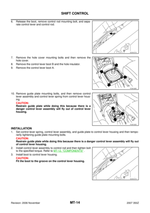
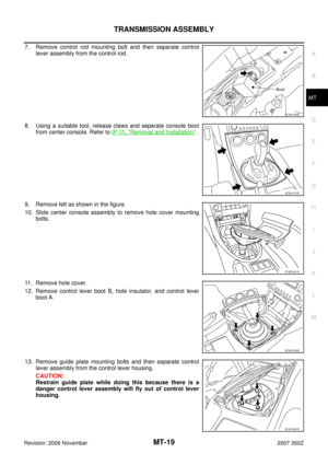
6. Release the boot, remove control rod mounting bolt, and sepa-
rate control lever and control rod.
7. Remove the hole cover mounting bolts and then remove the
hole cover.
8. Remove the control lever boot B and the hole insulator.
9. Remove the control lever boot A.
10. Remove guide plate mounting bolts, and then remove control
lever assembly and control lever spring from control lever hous-
ing.
CAUTION:
Restrain guide plate while doing this because there is a
danger control lever assembly will fly out of control lever
housing.
INSTALLATION
1. Set control lever spring, control lever assembly, and guide plate to control lever housing and then tempo-
rarily tightening guide plate mounting bolts.
CAUTION:
Restrain guide plate while doing this because there is a danger control lever assembly will fly out
of control lever housing.
2. Install control lever assembly to control rod and then tighten bolt
to the specified torque. Refer to MT-12, "
COMPONENTS" .
3. Install boot to control lever housing.
CAUTION:
Fit the boot to the groove on the control lever housing.
SCIA1671E
PCIB1926E
PCIB1932E
SCIA1671E
Page 15 of 62
 until it comes to a st")
SHIFT CONTROL
MT-15
D
E
F
G
H
I
J
K
L
MA
B
MT
Revision: 2006 November2007 350Z
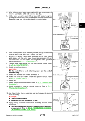
4. After shifting control lever assembly into 6th gear, push it toward
reverse gear (to the right) until it comes to a stop.
5. At the point where the control lever assembly stops, bring the
guide plate closer until guide plate stopper contacts control lever
assembly claw, and then loosely tighten mounting bolt A.
6. After shifting control lever assembly into 5th gear, push it toward
reverse gear (to the right) until it comes to a stop.
7. At the point where control lever assembly stops, bring guide
plate closer until the guide plate stopper contacts control lever
assembly claw, and then tighten mounting bolt C to the specified
torque. Refer to MT-12, "
COMPONENTS" .
8. Tighten guide plate bolts A and B to the specified torque. Refer
to MT-12, "
COMPONENTS" .
9. Install control lever boot A.
CAUTION:
Fit the control lever boot A to the groove on the control
lever housing.
10. Install hole insulator and control lever boot B.
11. Install hole cover and tighten bolts to the specified torque. Refer
to MT-12, "
COMPONENTS" .
12. Install felt.
13. Install center console assembly. Refer to IP-11, "
Removal and
Installation" .
14. Install console boot to center console assembly. Refer to IP-11,
"Removal and Installation" .
15. As shown in the figure, assemble seat and insulator to control
lever assembly.
CAUTION:
�Do not reuse insulator.
�Be careful with the orientation of seat.
16. Apply locking sealant to control lever assembly threads, install
shift knob.
�Use Genuine Medium Strength Thread Locking Sealant or
an equivalent. Refer to GI-45, "
RECOMMENDED CHEMI-
CAL PRODUCTS AND SEALANTS" .
SCIA1665E
SCIA1666E
SCIA1771E
Page 16 of 62

MT-16
SHIFT CONTROL
Revision: 2006 November2007 350Z
CAUTION:
Remove the remaining adhesive on control lever and shift knob threads.
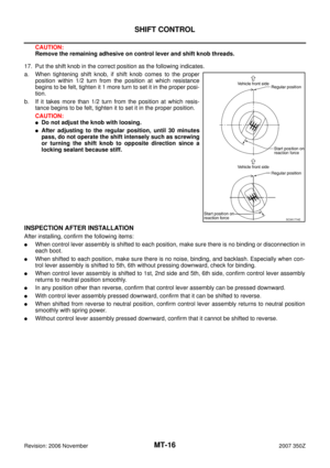
17. Put the shift knob in the correct position as the following indicates.
a. When tightening shift knob, if shift knob comes to the proper
position within 1/2 turn from the position at which resistance
begins to be felt, tighten it 1 more turn to set it in the proper posi-
tion.
b. If it takes more than 1/2 turn from the position at which resis-
tance begins to be felt, tighten it to set it in the proper position.
CAUTION:
�Do not adjust the knob with loosing.
�After adjusting to the regular position, until 30 minutes
pass, do not operate the shift intensely such as screwing
or turning the shift knob to opposite direction since a
locking sealant because stiff.
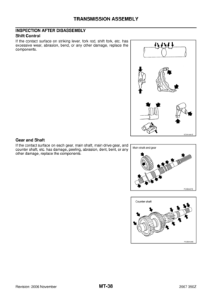
INSPECTION AFTER INSTALLATION
After installing, confirm the following items:
�When control lever assembly is shifted to each position, make sure there is no binding or disconnection in
each boot.
�When shifted to each position, make sure there is no noise, binding, and backlash. Especially when con-
trol lever assembly is shifted to 5th, 6th without pressing downward, check for binding.
�When control lever assembly is shifted to 1st, 2nd side and 5th, 6th side, confirm control lever assembly
returns to neutral position smoothly.
�In any position other than reverse, confirm that control lever assembly can be pressed downward.
�With control lever assembly pressed downward, confirm that it can be shifted to reverse.
�When shifted from reverse to neutral position, confirm control lever assembly returns to neutral position
smoothly with spring power.
�Without control lever assembly pressed downward, confirm that it cannot be shifted to reverse.
SCIA1774E