Page 955 of 1449

REAR AXLE -Troubleshooting 27B-9
ERASING THE DIAGNOSIS CODES
Connect the MUT-IIto the 16-pin diagnosis connector and
erase the diagnosis code. (Refer to GROUP 00 – How to
Use Troubleshooting/Inspection Service Points.)
Caution
Turn the ignition switch to the LOCK (OFF) position before
connecting or disconnecting the MUT-II.
INSPECTION CHART FOR DIAGNOSIS CODE
Diagnosis
code No.Diagnosis itemsReference page
12Power supply voltage (valve power supply) systemopen- or short-circuitRefer to
GROUP22
13Failsafe relay system open- or short-circuit
GROUP22.
21FR wheel speed sensor systemopen- or short-circuit
22FL wheel speed sensor systemopen- or short-circuit
23RR wheel speed sensor systemopen- or short-circuit
24RL wheel speed sensor systemopen- or short-circuit
25Wrong-diameter tire
26Wheel speed sensor (faulty output signal)
31Steer sensor (ST-1, ST-2, ST-N) systemopen- or short-circuit
32Steer sensor (ST-N) systemshort-circuit
33fixed
34Steer sensor (ST-1, ST-2) systemshort-circuit or output
fixed
41TPS systemopen-circuit or ground
42short-circuit
45Pressure sensor systemopen-circuit or ground
46open earth
47abnormal power supply
51G sensor (longitudinal) systemopen- or short-circuit
52defective sensor
56G sensor (lateral) systemopen- or short-circuit
57defective sensor
Page 956 of 1449
REAR AXLE -Troubleshooting 27B-10
Diagnosis
code No.Reference page Diagnosis items
61Stop lamp switch systemopen-circuitRefer to
GROUP22
62ACD mode changeover switchstuck
GROUP22.
63Parking brake switch systemshort-circuit or not re-
turned
65ABS monitor systemopen-circuit or defective
ABS
71Proportioning valve systemopen- or short-circuit27B-11
72Directional control valve (right) systemopen- or short-circuit27B-12
73Directional control valve (left) systemopen- or short-circuit27B-13
74Proportioning valve systemopen- or short-circuitRefer to
GROUP22
81Electric pump relay systemopen- or short-circuit
GROUP22.
82electric pump malfunction
or pressure sensor defect
84AYC control error–
85ACD control errorRefer to
GROUP 22.
NOTE
Code No.84 is not a code number output due to malfunction, but a code number output when control
for the 4WD-ECU to protect the AYC is stopped in excessive driving. AYC control can be recovered
by turning the ignition switch ON to OFF to ON.
Page 957 of 1449

REAR AXLE-Troubleshooting 27B-11
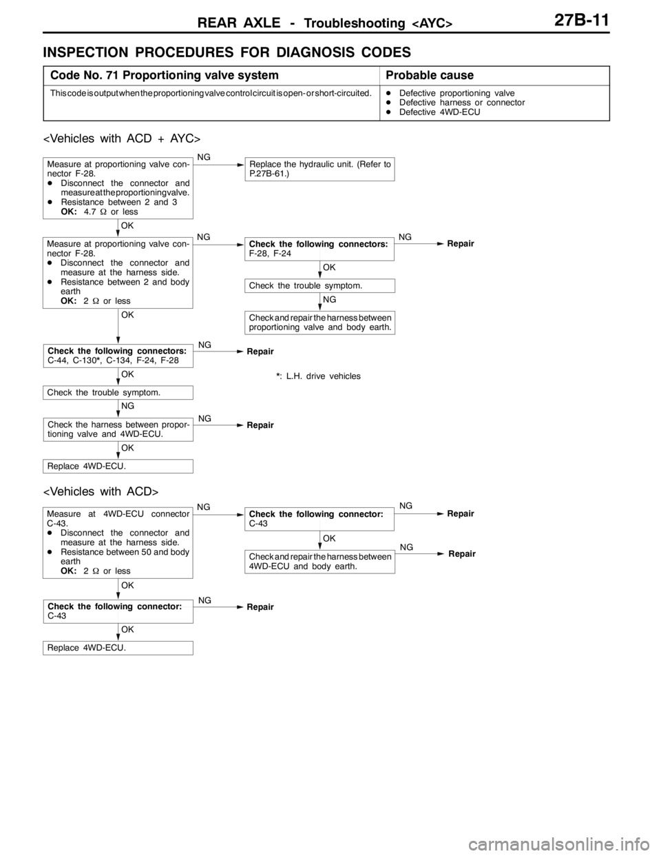
INSPECTION PROCEDURES FOR DIAGNOSIS CODES
Code No. 71 Proportioning valve systemProbable cause
This code is output when the proportioning valve control circuit is open- or short-circuited.DDefective proportioning valve
DDefective harness or connector
DDefective 4WD-ECU
NG
Check and repair the harness between
proportioning valve and body earth.
OK
Check the trouble symptom.
OK
Measure at proportioning valve con-
nector F-28.
DDisconnect the connector and
measure at the harness side.
DResistance between 2 and body
earth
OK:2Ωor lessNGCheck the following connectors:
F-28, F-24NG
Repair
Measure at proportioning valve con-
nector F-28.
DDisconnect the connector and
measure at the proportioning valve.
DResistance between 2 and 3
OK:4.7Ωor lessNGReplace the hydraulic unit. (Refer to
P.27B-61.)
OK
Replace 4WD-ECU.
NG
Check the harness between propor-
tioning valve and 4WD-ECU.NG
Repair
OK
Check the trouble symptom.
OK
Check the following connectors:
C-44, C-130*, C-134, F-24, F-28NG
Repair
*: L.H. drive vehicles
OK
Replace 4WD-ECU.
OK
Check the following connector:
C-43NG
Repair
OK
Check and repair the harness between
4WD-ECU and body earth.
Measure at 4WD-ECU connector
C-43.
DDisconnect the connector and
measure at the harness side.
DResistance between 50 and body
earth
OK:2Ωor lessNGCheck the following connector:
C-43NG
Repair
NG
Repair
Page 958 of 1449

REAR AXLE -Troubleshooting 27B-12
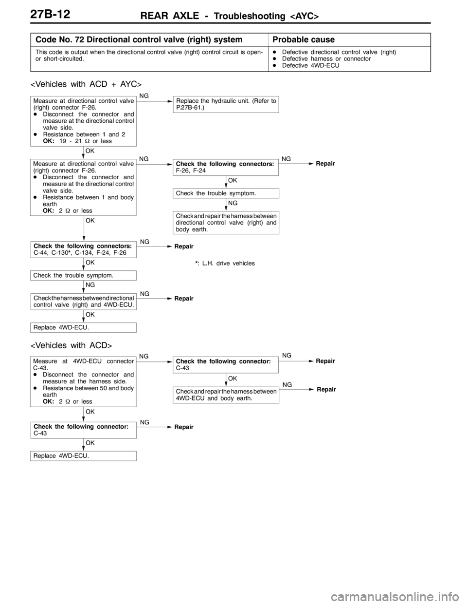
Code No. 72 Directional control valve (right) systemProbable cause
This code is output when the directional control valve (right) control circuit is open-
or short-circuited.DDefective directional control valve (right)
DDefective harness or connector
DDefective 4WD-ECU
NG
Check and repair the harness between
directional control valve (right) and
body earth.
OK
Check the trouble symptom.
OK
Replace 4WD-ECU.
NG
Check the harness between directional
control valve (right) and 4WD-ECU.NG
Repair
OK
Check the trouble symptom.
OK
Check the following connectors:
C-44, C-130*, C-134, F-24, F-26NG
Repair
OK
Measure at directional control valve
(right) connector F-26.
DDisconnect the connector and
measure at the directional control
valve side.
DResistance between 1 and body
earth
OK:2Ωor lessNGCheck the following connectors:
F-26, F-24NG
Repair
Measure at directional control valve
(right) connector F-26.
DDisconnect the connector and
measure at the directional control
valve side.
DResistance between 1 and 2
OK:19 - 21Ωor lessNGReplace the hydraulic unit. (Refer to
P.27B-61.)
*: L.H. drive vehicles
OK
Check and repair the harness between
4WD-ECU and body earth.
Measure at 4WD-ECU connector
C-43.
DDisconnect the connector and
measure at the harness side.
DResistance between 50 and body
earth
OK:2Ωor lessNGCheck the following connector:
C-43NG
Repair
OK
Replace 4WD-ECU.
OK
Check the following connector:
C-43NG
RepairNG
Repair
Page 959 of 1449

REAR AXLE -Troubleshooting 27B-13
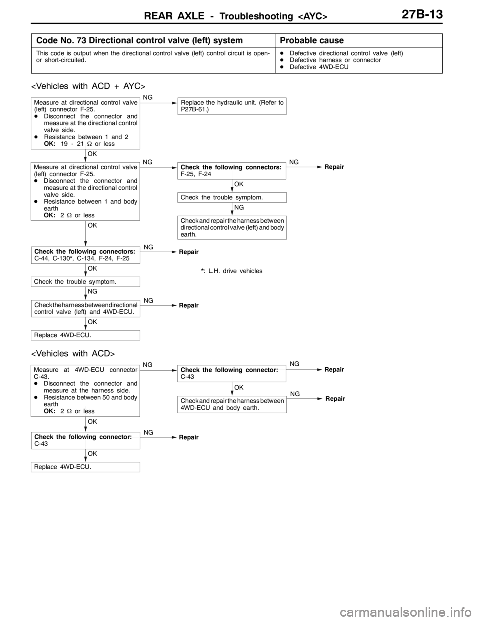
Code No. 73 Directional control valve (left) systemProbable cause
This code is output when the directional control valve (left) control circuit is open-
or short-circuited.DDefective directional control valve (left)
DDefective harness or connector
DDefective 4WD-ECU
NG
Check and repair the harness between
directional control valve (left) and body
earth.
OK
Check the trouble symptom.
OK
Replace 4WD-ECU.
NG
Check the harness between directional
control valve (left) and 4WD-ECU.NG
Repair
OK
Check the trouble symptom.
OK
Check the following connectors:
C-44, C-130*, C-134, F-24, F-25NG
Repair
OK
Measure at directional control valve
(left) connector F-25.
DDisconnect the connector and
measure at the directional control
valve side.
DResistance between 1 and body
earth
OK:2Ωor lessNGCheck the following connectors:
F-25, F-24NG
Repair
Measure at directional control valve
(left) connector F-25.
DDisconnect the connector and
measure at the directional control
valve side.
DResistance between 1 and 2
OK:19 - 21Ωor lessNGReplace the hydraulic unit. (Refer to
P27B-61.)
*: L.H. drive vehicles
OK
Check and repair the harness between
4WD-ECU and body earth.
Measure at 4WD-ECU connector
C-43.
DDisconnect the connector and
measure at the harness side.
DResistance between 50 and body
earth
OK:2Ωor lessNGCheck the following connector:
C-43NG
Repair
OK
Replace 4WD-ECU.
OK
Check the following connector:
C-43NG
RepairNG
Repair
Page 960 of 1449

REAR AXLE -Troubleshooting REAR AXLE -Troubleshooting 27B-14
INSPECTION CHART FOR TROUBLE SYMPTOMS
Trouble symptomInspection
procedure No.Reference
page
Communication between MUT-IIand the whole system is not possible.1Refer to
GROUP22
Communication between MUT-IIand 4WD-ECU is not possible.2
GROUP22.
3 ACD mode indicator lamps do not light up when the ignition key is turned to “ON”
(engine stationary).3
3 ACD mode indicator lamps remain lit up after the engine has started.4
AYC is inoperative.
Unable to start or accelerate on slippery road surfaces.527B-14
Rear tires are noisy during low-speed cornering.
Vehicle skews.627B-15
Noise is produced from the torque transfer differential during turning.727B-15
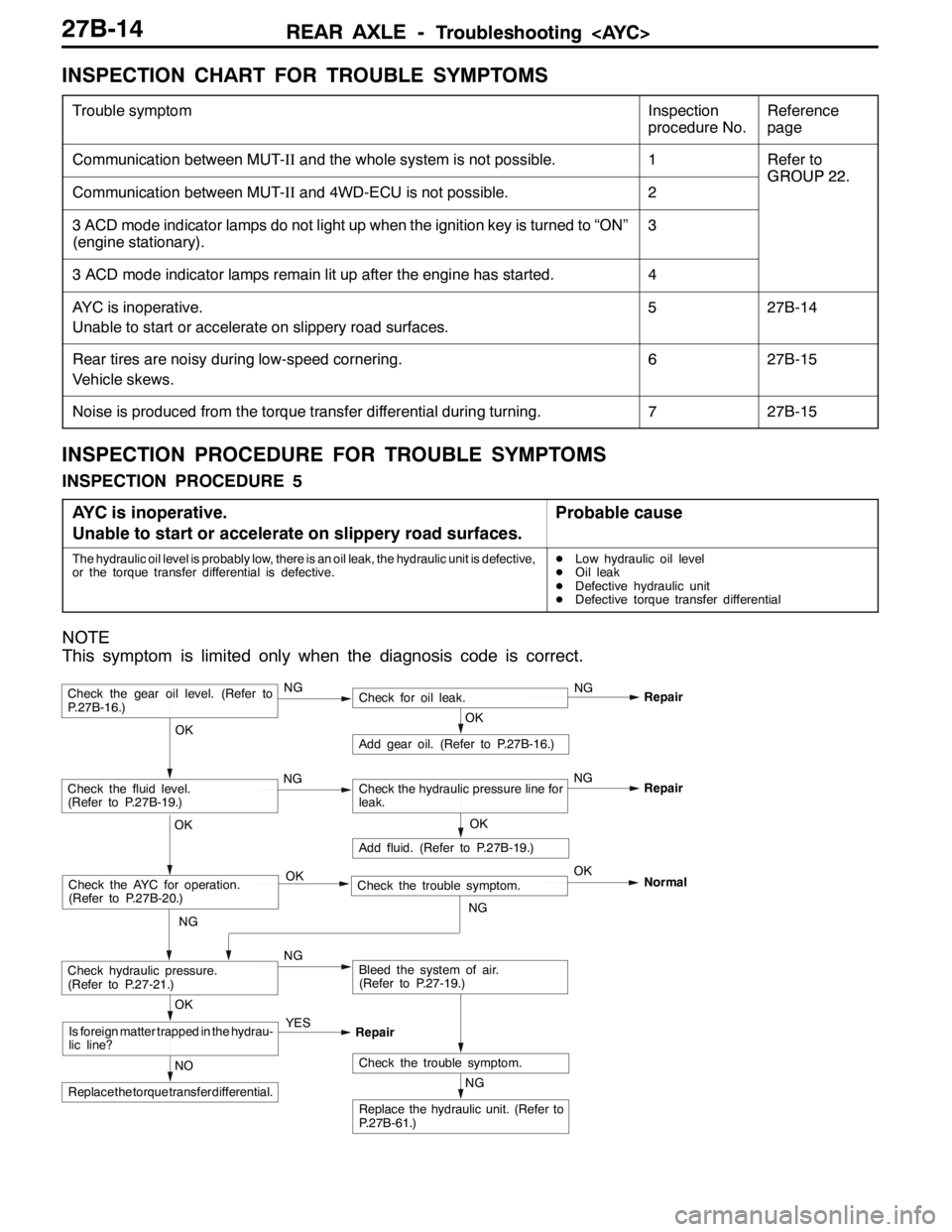
INSPECTION PROCEDURE FOR TROUBLE SYMPTOMS
INSPECTION PROCEDURE 5
AYC is inoperative.
Unable to start or accelerate on slippery road surfaces.
Probable cause
The hydraulic oil level is probably low, there is an oil leak, the hydraulic unit is defective,
or the torque transfer differential is defective.DLow hydraulic oil level
DOil leak
DDefective hydraulic unit
DDefective torque transfer differential
NOTE
This symptom is limited only when the diagnosis code is correct.
NG
Replace the hydraulic unit. (Refer to
P.27B-61.)
NG
Add fluid. (Refer to P.27B-19.)
OKRepair
Check the trouble symptom.NO
Replace the torque transfer differential.
OK
Is foreign matter trapped in the hydrau-
lic line?YES
Repair
OK
Check the fluid level.
(Refer to P.27B-19.)Check the hydraulic pressure line for
leak.
OK
Add gear oil. (Refer to P.27B-16.)
OK
Check hydraulic pressure.
(Refer to P.27-21.)NGBleed the system of air.
(Refer to P.27-19.)
Check the gear oil level. (Refer to
P.27B-16.)NGCheck for oil leak.NG
Repair
Check the AYC for operation.
(Refer to P.27B-20.)Check the trouble symptom. OKOK
NGNormal
NGNG
Page 962 of 1449

REAR AXLE -On-vehicle Service27B-16
DATA LIST REFERENCE TABLE
For check, refer to GROUP 22.
ACTUATOR TEST REFERENCE TABLE
For check, refer to GROUP 22.
CHECK AT 4WD-ECU TERMINALS
For check, refer to GROUP 22.
ON-VEHICLE SERVICE
REAR AXLE TOTAL BACKLASH CHECK
1. Park the vehicle on a flat, level surface.
2. Move the transmission control lever to the neutral position.
Apply the parking brake. Raise the vehicle on a jack.
3. Turn the companion flange clockwise as far as it will go.
Make the mating mark on the dust cover of the companion
flange and on the differential carrier.
4. Turn the companion flange anti-clockwise as far as it
will go, and measure the amount of distance the mating
marks moved.
Limit: 6 mm
5. If the backlash exceeds the limit value, replace the
differential carrier assembly.
GEAR OIL LEVEL CHECK
1. Remove the filler plug.
2. Check that the gear oil level is within the specified range
from the bottom end of the filler plug hole.
3. If the gear oil level exceeds the standard value, add the
specified gear oil up to the bottom end of the filler plug
hole.
Specified gear oil:
Hypoid gear oil
MITSUBISHI Genuine Gear Oil Part No. 8149630
EX, CASTROL HYPOY LS (GL-5, SAE 90),
SHELL-LSD (GL-5, SAE 80W - 90) or equivalent
4. Fit the filler plug and tighten it to the specified torque.
Tightening torque: 49±9 N·m
Mating marks
Upper
limit
Lower
limit
Gear oil
8mm
Page 1043 of 1449
BASIC BRAKE SYSTEM 35A.........................................
ANTI-SKID BRAKING SYSTEM (ABS) <4WD> 35B......................
35A-1
SERVICE BRAKES
CONTENTS