Page 1074 of 1449

ABS <4WD> -Special Tools/Troubleshooting35B-4
SPECIAL TOOLS
ToolNumberNameUse
MB991502MUT-IIsub
assemblyFor checking of ABS
(Diagnosis code display when using the
MUT-II)
MB991529Diagnosis code
check harnessFor checking of ABS
(Diagnosis code display when using the ABS
warning lamp)
MB991348Test harness setFor checking of G sensor
TROUBLESHOOTING
STANDARD FLOW OF DIAGNOSTIC TROUBLESHOOTING
Refer to GROUP 00 - How to Use Troubleshooting/Inspection Service Points.
NOTES WITH REGARD TO DIAGNOSIS
1. The phenomena listed in the following table are not abnormal.
PhenomenonExplanation of phenomenon
System check soundWhen starting the engine, a thudding sound can sometimes be heard coming from inside
the engine compartment, but this is because the system operation check is being
performed, and is not an abnormality.
ABS operation sound1. Sound of the motor inside the ABS hydraulic unit operation. (whine)
2. Sound is the generated along with vibration of the brake pedal. (scraping)
3. When ABS operates, sound is generated from the vehicle chassis due to repeated
brake application and release.
(Thump: suspension; squeak: tyres)
System check soundWhen depressing the brake pedal during driving, a shock is sometime felt.
2. For road surfaces such as snow-covered roads and gravel roads, the braking distance for vehicles
with ABS can sometimes be longer than that for other vehicles. Accordingly, advise the customer
to drive safely on such roads by lowering the vehicle speed and not being too overconfident.
3. Diagnosis detection condition can vary depending on the diagnosis code.
Make sure that checking requirements listed in the “Comment” are satisfied when checking the trouble
symptom again.
Page 1090 of 1449

ABS <4WD> -Troubleshooting35B-20
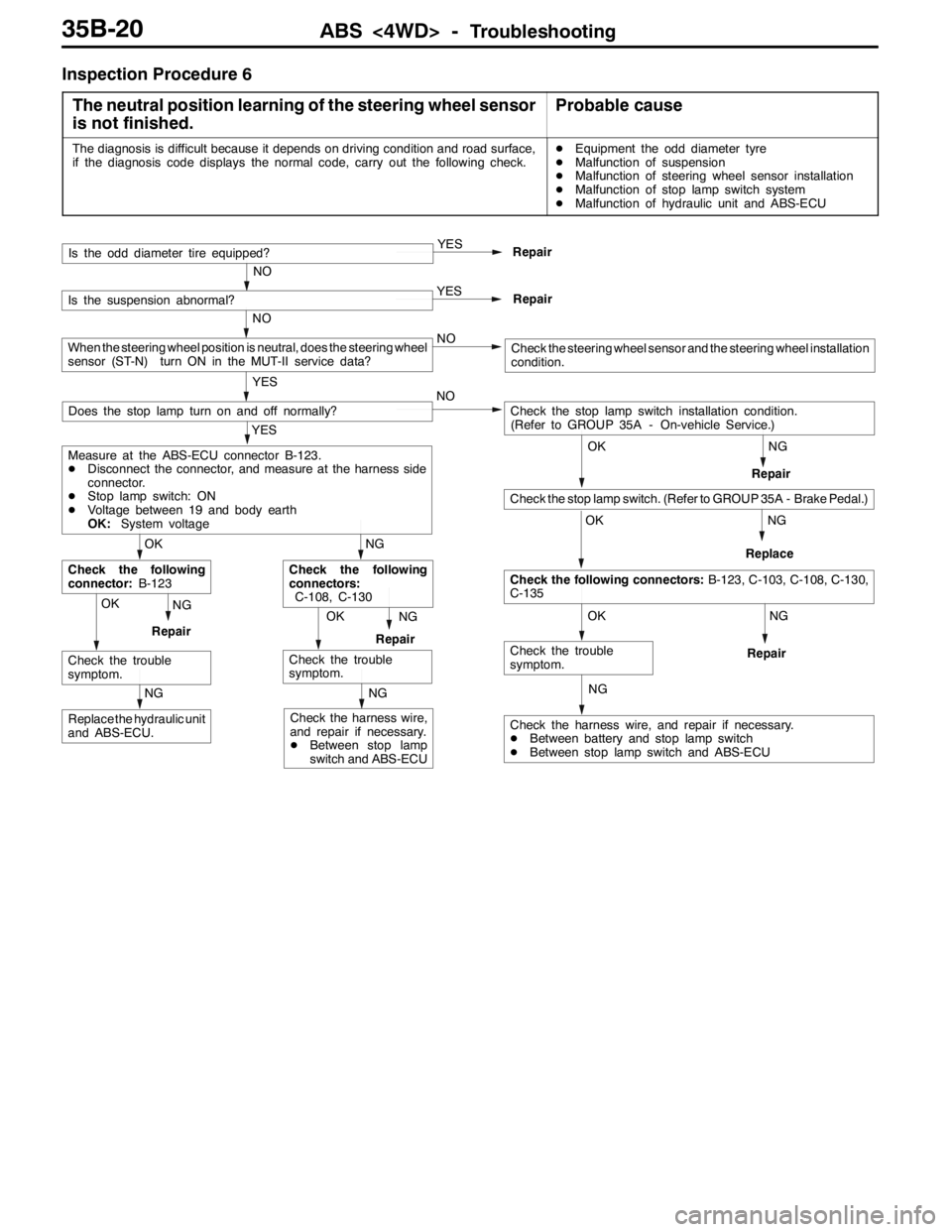
Inspection Procedure 6
The neutral position learning of the steering wheel sensor
is not finished.
Probable cause
The diagnosis is difficult because it depends on driving condition and road surface,
if the diagnosis code displays the normal code, carry out the following check.DEquipment the odd diameter tyre
DMalfunction of suspension
DMalfunction of steering wheel sensor installation
DMalfunction of stop lamp switch system
DMalfunction of hydraulic unit and ABS-ECU
NG
NG
NG
NG
Check the harness wire, and repair if necessary.
DBetween battery and stop lamp switch
DBetween stop lamp switch and ABS-ECU
OK
Check the trouble
symptom.
OK
Check the following connectors:B-123, C-103, C-108, C-130,
C-135
OK
Check the stop lamp switch. (Refer to GROUP 35A - Brake Pedal.)
Check the stop lamp switch installation condition.
(Refer to GROUP 35A - On-vehicle Service.) NO
Repair
OKNG
RepairOKNG
RepairReplace
NG
Replace the hydraulic unit
and ABS-ECU.
NG
Check the harness wire,
and repair if necessary.
DBetween stop lamp
switch and ABS-ECURepair
Check the trouble
symptom.
NG
Check the following
connectors:
C-108, C-130
Check the trouble
symptom.
OK
Check the following
connector:B-123
YES
Measure at the ABS-ECU connector B-123.
DDisconnect the connector, and measure at the harness side
connector.
DStop lamp switch: ON
DVoltage between 19 and body earth
OK:System voltage
Does the stop lamp turn on and off normally?
YES
Repair
NO
Is the odd diameter tire equipped?
YES
Repair
NO
Is the suspension abnormal?
NO
YES
When the steering wheel position is neutral, does the steering wheel
sensor (ST-N) turn ON in the MUT-II service data?Check the steering wheel sensor and the steering wheel installation
condition.
Page 1098 of 1449

ABS <4WD> -On-vehicle Service35B-28
SymptomRemedy Probable causes
Noisy or disturbed waveformOpen circuit in sensorReplace sensor
Open circuit in harnessCorrect harness
Incorrectly mounted wheel speed sensorMount correctly
ABS rotor with missing or damaged teethReplace ABS rotor
Caution
Because the wheel speed sensor cables move together with the front and rear suspension, they
vibrate greatly when driving over poor road surfaces. As a result, the sensor harnesses should also
be shaken when monitoring of output waveforms of the wheel speed sensors in order to simulate
conditions such as driving over poor road surfaces.
HYDRAULIC UNIT CHECK
1. Jack up the vehicle and support the vehicle with rigid racks placed at the specified jack-up points
or place the wheels which are checked on the rollers of the braking force tester.
Caution
(1) The roller of the braking force tester and the tyre should be dry during testing.
(2) When testing the front brakes, apply the parking brake, and when testing the rear brakes,
stop the front wheels by chocking them.
2. Turn the ignition key to the “LOCK” (OFF) position and set the MUT-II.
Caution
Turn the ignition key to the “LOCK” (OFF) position before connecting or disconnecting the
MUT-II.
3. After checking that the shift lever is in neutral, start the engine.
4. Use the MUT-IIto force-drive the actuator.
NOTE
(1) During the actuator test, the ABS warning lamp will illuminate and the anti-skid control will be
cancelled.
(2) When the ABS has been interrupted by the fail-safe function, the MUT-IIactuator testing cannot
be carried out.
5. Turn the wheel by hand and check the change in braking force when the brake pedal is depressed.
When using the braking force tester, depress the brake pedal until the braking force is at the following
values, and check that the braking force decreases when the actuator is force-driven.
Front wheel785 - 981 N
Rear wheel588 - 784 N
Page 1345 of 1449

CHASSIS ELECTRICAL -Headlamp Assembly54A-25
4. If the fuel tank is not full, place a weight in luggage room
of vehicle to simulate weight of a full tank 0.8 kg per litre.
5. There should be no other load in the vehicle other than
driver or substituted weight of approximately 75 kg placed
in driver’s position.
6. Thoroughly clean headlamp lenses.
7. Place the vehicle on a level floor, perpendicular to a flat
screen 10m away from the bulb center - marks on the
headlamp lens.
8. Rock vehicle sideways to allow vehicle to assume its
normal position.
9. Bounce the front suspension through three (3) oscillations
by applying the body weight to hood or bumper.
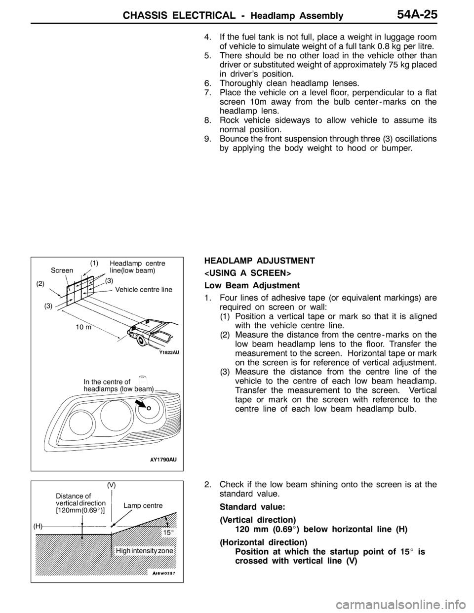
HEADLAMP ADJUSTMENT
Low Beam Adjustment
1. Four lines of adhesive tape (or equivalent markings) are
required on screen or wall:
(1) Position a vertical tape or mark so that it is aligned
with the vehicle centre line.
(2) Measure the distance from the centre - marks on the
low beam headlamp lens to the floor. Transfer the
measurement to the screen. Horizontal tape or mark
on the screen is for reference of vertical adjustment.
(3) Measure the distance from the centre line of the
vehicle to the centre of each low beam headlamp.
Transfer the measurement to the screen. Vertical
tape or mark on the screen with reference to the
centre line of each low beam headlamp bulb.
2. Check if the low beam shining onto the screen is at the
standard value.
Standard value:
(Vertical direction)
120 mm (0.69_) below horizontal line (H)
(Horizontal direction)
Position at which the startup point of 15_is
crossed with vertical line (V)
(1)
(2)(3)
Headlamp centre
line(low beam)
Vehicle centre line
Screen
10 m
In the centre of
headlamps (low beam) (3)
Distance of
vertical direction
[120mm(0.69_)]Lamp centre
15_
High intensity zone (H)(V)