Page 1012 of 1449

WHEEL AND TYRE -Troubleshooting31-4
WHEEL BALANCE ACCURACY
PURPOSE
This section contains tips and procedures for
achieving accurate wheel balance. Steering wheel
vibration and /or body shake can result if any of
these procedures are not carefully observed.
1. Wheels and tires must be properly mounted
on a balancer in order to achieve correct
balance. Centering the wheel on the shaft of
the balancer is essential for proper mounting.
2. Off-the-car wheel balancers must be calibrated
periodically to ensure good balancing results.
An inaccurately calibrated balancer could cause
unnecessary replacement of tires, shocks,
suspension components, or steering
components.Check your balancer’s calibration approximately
every 100 balances. Your wheel balancer’s
instruction manual should include calibration
procedures. If the calibration procedures
specifically for your balancer are missing, use the
generic steps in this section for zero calibration,
static balance, and dynamic balance checks. The
wheel balancer calibration checks are also
described in the flowchart. (Refer to P.31-5.)
PROCEDURE
Balancing Tips
1. Confirm that the balancer’s cone and the wheel
mounting cone are undamaged and free of
dirt and rust.
2. On this vehicle the wheel’s center hole on the
hub side has a chamfered edge. Use a
back-mounting cone on your wheel balancer
to center the wheel on the balancer shaft.3. Install a wheel mounting cone. The appropriate
size cone for this vehicle is 67.0 mm.
4. Before balancing the wheel, remove any wheel
weights from both sides. Also check both sides
for any damage.
5. When installing wheel weights, hammer them
at a straight (not diagonal) angle.
Hub/shaft assembly
Spring plateClamping cup
Wheel mounting
cone
Standard passenger
car wheelWing nut
Confirming Proper Balance
1. After balancing the wheel, loosen the wing nut
and turn the wheel 180°against the balancer’s
hub. Then retighten the wing nut and check
the balance again. Repeat wheel balance if
necessary.2. Turn the wheel again 180°against the
balancer’s hub. If the wheel becomes
out-of-balance each time it is turned against
the balancer’s hub, the wheel balancer may
require calibration.
Wheel Balancer Calibration Checks
1. Mount an undamaged original-equipment alloy
rim and tire assembly (wheel) onto your
off-the-car wheel balancer. Balance the wheel.2.<>
Loosen the balancer wing nut, rotate the wheel
a half turn (180°), and retighten the nut.
Recheck the balance.
Page 1027 of 1449
33A-1
FRONT
SUSPENSION
CONTENTS
GENERAL INFORMATION 2..................
SERVICE SPECIFICATIONS 3.................
SPECIAL TOOLS 3...........................
ON-VEHICLE SERVICE 4.....................
Wheel Alignment Check and Adjustment 4.......Ball Joint Dust Cover Check 5..................
STRUT ASSEMBLY 6.........................
LOWER ARM ASSEMBLY 9..................
STABILIZER BAR 12.........................
CROSSMEMBER BAR 15.....................
Page 1028 of 1449
FRONT SUSPENSION -General Information33A-2
GENERAL INFORMATION
The front suspension is a McPherson strut with
coil spring. The shock absorber is gas-filled
hydraulic double-acting type.
COIL SPRING
ItemRS ,
RS-IIRS
Wire diameter�·average
diameter�·free length mm14�·155�·28114�·155�·275
CONSTRUCTION DIAGRAM
Stabilizer barCoil spring
Strut assembly
(shock absorber) Crossmember
Lower armStrut insulator
Stabilizer link
Crossmember bar
Lower arm bushing
(pillow ball bushing with rubber)
Page 1029 of 1449

FRONT SUSPENSION -Service Specifications/Special Tools33A-3
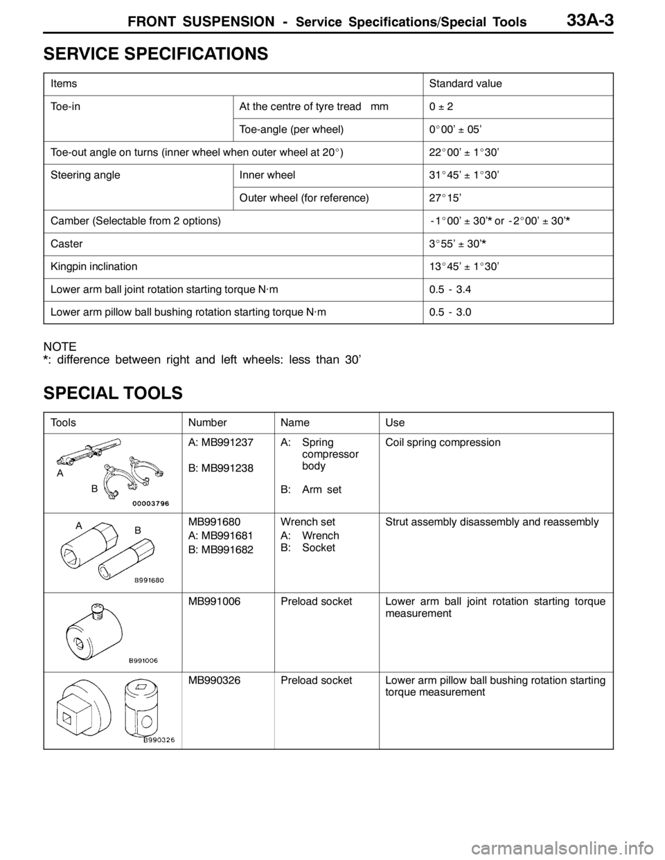
SERVICE SPECIFICATIONS
ItemsStandard value
Toe-inAt the centre of tyre tread mm0±2
Toe-angle (per wheel)0_00’±05’
Toe-out angle on turns (inner wheel when outer wheel at 20_)22_00’±1_30’
Steering angleInner wheel31_45’±1_30’
Outer wheel (for reference)27_15’
Camber (Selectable from 2 options)-1_00’±30’* or - 2_00’±30’*
Caster3_55’±30’*
Kingpin inclination13_45’±1_30’
Lower arm ball joint rotation starting torque N·m0.5 - 3.4
Lower arm pillow ball bushing rotation starting torque N·m0.5 - 3.0
NOTE
*: difference between right and left wheels: less than 30’
SPECIAL TOOLS
ToolsNumberNameUse
B
A
A: MB991237
B: MB991238A: Spring
compressor
body
B: Arm setCoil spring compression
BAMB991680
A: MB991681
B: MB991682Wrench set
A: Wrench
B: SocketStrut assembly disassembly and reassembly
MB991006Preload socketLower arm ball joint rotation starting torque
measurement
MB990326Preload socketLower arm pillow ball bushing rotation starting
torque measurement
Page 1030 of 1449

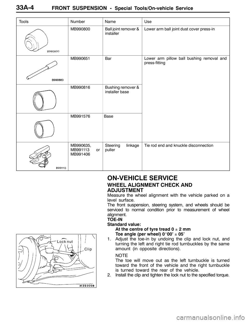
FRONT SUSPENSION -Special Tools/On-vehicle Service33A-4
Tools UseName Number
MB990800Ball joint remover &
installerLower arm ball joint dust cover press-in
MB990651BarLower arm pillow ball bushing removal and
press-fitting
MB990816Bushing remover &
installer base
MB991576Base
MB990635,
MB991113 or
MB991406Steering linkage
pullerTie rod end and knuckle disconnection
ON-VEHICLE SERVICE
WHEEL ALIGNMENT CHECK AND
ADJUSTMENT
Measure the wheel alignment with the vehicle parked on a
level surface.
The front suspension, steering system, and wheels should be
serviced to normal condition prior to measurement of wheel
alignment.
TOE-IN
Standard value:
At the centre of tyre tread 0±2mm
Toe angle (per wheel) 0_00’±05’
1. Adjust the toe-in by undoing the clip and lock nut, and
turning the left and right tie rod turnbuckles by the same
amount (in opposite directions).
NOTE
The toe will move out as the left turnbuckle is turned
toward the front of the vehicle and the right turnbuckle
is turned toward the rear of the vehicle.
2. Install the clip and tighten the lock nut to the specified torque.
Clip
Lock nut
Page 1031 of 1449

FRONT SUSPENSION -On-vehicle Service33A-5
Tightening torque: 52±2 N·m
3. Confirm that the toe-in is at the standard value.
4. Use a turning radius gauge to check that the steering
angle is at the standard value.
Standard value:
Inner wheels31_45’±1_30’
Outer wheels (for reference)27_15’
TOE-OUT ANGLE ON TURNS
To check the steering linkage, especially after the vehicle
has been involved in an accident or if an accident is presumed,
it is advisable to check the toe-out angle on turns in addition
to the wheel alignment.
Conduct this test on the left turn as well as on the right turn.
Standard value:
ItemsSpecifications
Toe-out angle on turns
(inner wheel when outer wheel at 20_)22_00’±1_30’
CAMBER, CASTER AND KINGPIN INCLINATION
Standard value:
ItemsSpecifications
Camber
(Selectable from 2 options)-1_00’±30’* or - 2_00’±30’*
Caster3_55’±30’*
Kingpin inclination13_45’±1_30’
NOTE
1. *: difference between right and left wheels must be less
than 30’
2. Caster and kingpin inclination are preset at the factory
and cannot be adjusted.
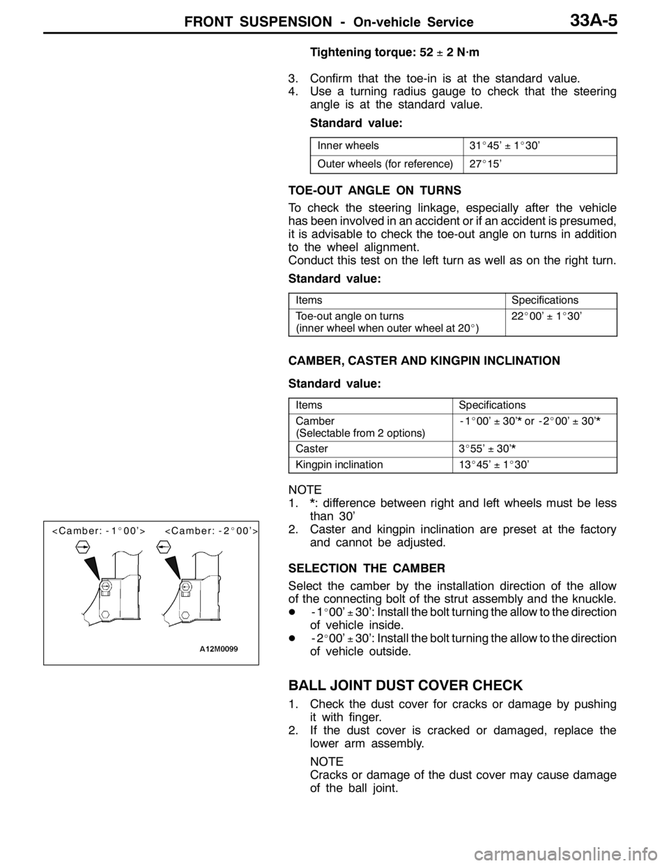
SELECTION THE CAMBER
Select the camber by the installation direction of the allow
of the connecting bolt of the strut assembly and the knuckle.
D-1
_00’±30’: Install the bolt turning the allow to the direction
of vehicle inside.
D-2
_00’±30’: Install the bolt turning the allow to the direction
of vehicle outside.
BALL JOINT DUST COVER CHECK
1. Check the dust cover for cracks or damage by pushing
it with finger.
2. If the dust cover is cracked or damaged, replace the
lower arm assembly.
NOTE
Cracks or damage of the dust cover may cause damage
of the ball joint.
Page 1032 of 1449
FRONT SUSPENSION -Strut Assembly33A-6
STRUT ASSEMBLY
REMOVAL AND INSTALLATION
Post-installation Operation
Wheel alignment check and adjustment (Refer to
P.33A-4.)
44±5N·m
3
21
167±9N·m
4
5
Removal steps
1. Front wheel speed sensor harness
bracket
2. Brake hose bracket3. Knuckle connection
4. Strut mounting nut
5. Strut assembly
Page 1033 of 1449

FRONT SUSPENSION -Strut Assembly33A-7
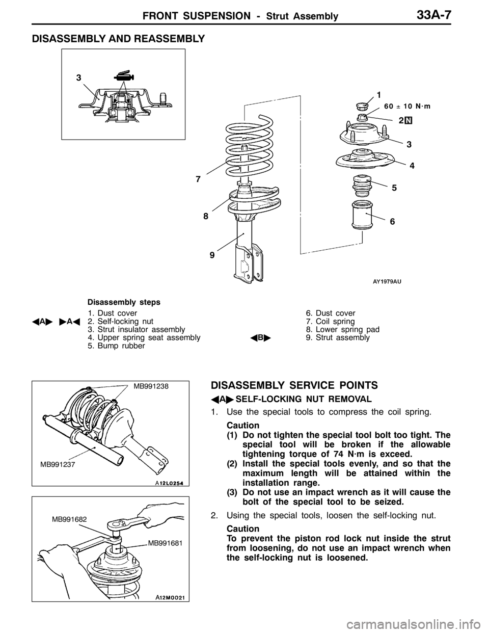
DISASSEMBLY AND REASSEMBLY
60±10 N·m
3
2
1
5
6
7
8
9
4
3
Disassembly steps
1. Dust cover
AA""AA2. Self-locking nut
3. Strut insulator assembly
4. Upper spring seat assembly
5. Bump rubber6. Dust cover
7. Coil spring
8. Lower spring pad
AB"9. Strut assembly
DISASSEMBLY SERVICE POINTS
AA"SELF-LOCKING NUT REMOVAL
1. Use the special tools to compress the coil spring.
Caution
(1) Do not tighten the special tool bolt too tight. The
special tool will be broken if the allowable
tightening torque of 74 N·m is exceed.
(2) Install the special tools evenly, and so that the
maximum length will be attained within the
installation range.
(3) Do not use an impact wrench as it will cause the
bolt of the special tool to be seized.
2. Using the special tools, loosen the self-locking nut.
Caution
To prevent the piston rod lock nut inside the strut
from loosening, do not use an impact wrench when
the self-locking nut is loosened.
MB991237
MB991238
MB991681
MB991682