Page 32 of 1449
BODY DIMENSIONS -Type A (Projected Dimensions)B-6
INSTALLATION OF SUSPENSIONmm
1
1
713902906
882
1,1101,186
765
86
852779
1,025
1,073
713700
370
372
290
288
857
888851
469
375
190
100
322
876
852
721
1,127
3
3
1213
14
15
16
171819
20
21
22
23
14
15
16
17182022
858
827
810
857
10
10
999
480
417
Page 36 of 1449
BODY DIMENSIONS -Type B (Actual-measurement Dimensions)B-10
INSTALLATION OF SUSPENSIONmm
1
17138109061,186713
852
700
387
389
295
293
890
190
857
777
1,025
1,075859
895853
104381
357
469
741
111
871
1,137
902
876780
4373
14
15
16
17
18
20
22
23
314
15
16
17
1820
22
10
10
498
Page 391 of 1449

GENERAL -How to Use Troubleshooting/Inspection Service Points00-13
INSPECTION SERVICE POINTS FOR A BLOWN
FUSE
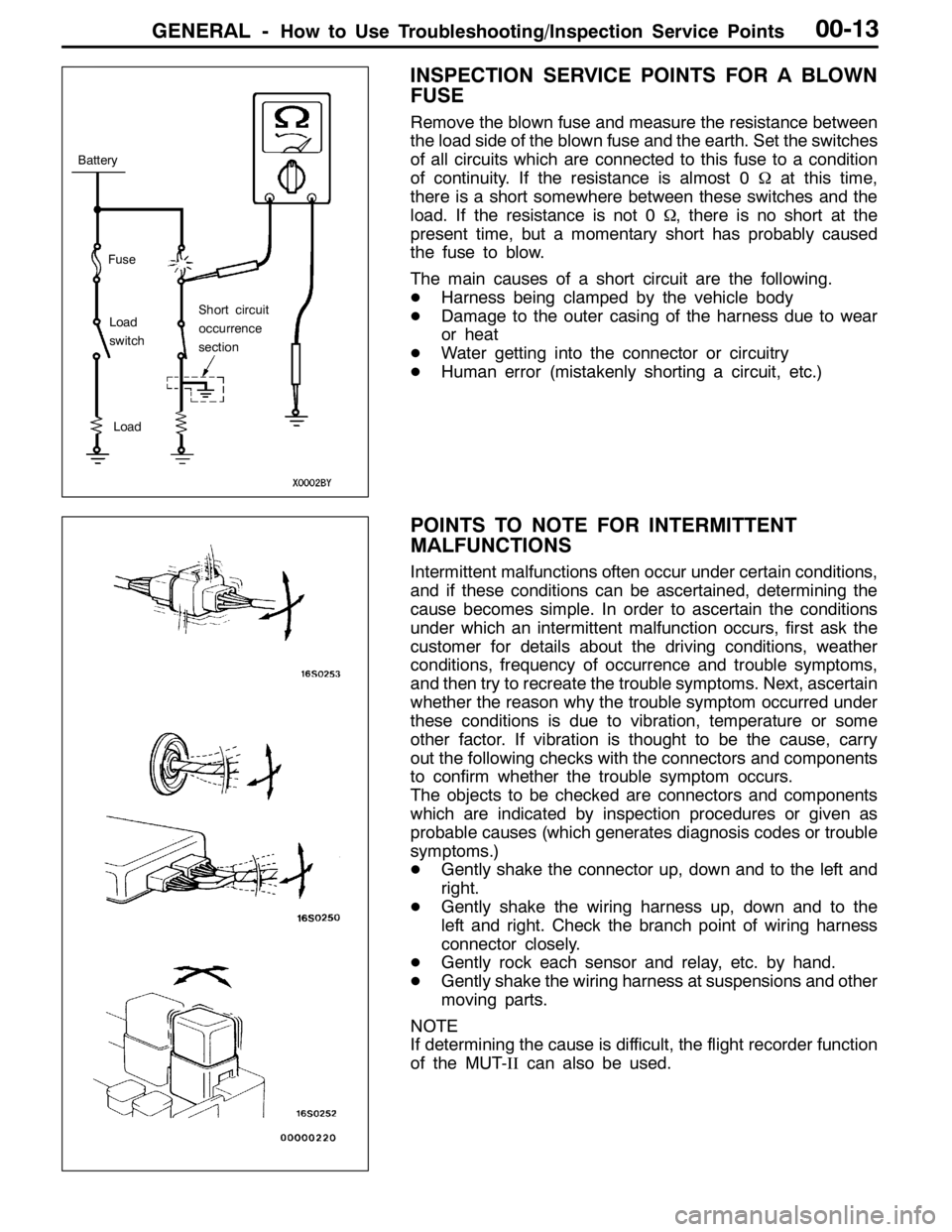
Remove the blown fuse and measure the resistance between
the load side of the blown fuse and the earth. Set the switches
of all circuits which are connected to this fuse to a condition
of continuity. If the resistance is almost 0Ωat this time,
there is a short somewhere between these switches and the
load. If the resistance is not 0Ω, there is no short at the
present time, but a momentary short has probably caused
the fuse to blow.
The main causes of a short circuit are the following.
DHarness being clamped by the vehicle body
DDamage to the outer casing of the harness due to wear
or heat
DWater getting into the connector or circuitry
DHuman error (mistakenly shorting a circuit, etc.)
POINTS TO NOTE FOR INTERMITTENT
MALFUNCTIONS
Intermittent malfunctions often occur under certain conditions,
and if these conditions can be ascertained, determining the
cause becomes simple. In order to ascertain the conditions
under which an intermittent malfunction occurs, first ask the
customer for details about the driving conditions, weather
conditions, frequency of occurrence and trouble symptoms,
and then try to recreate the trouble symptoms. Next, ascertain
whether the reason why the trouble symptom occurred under
these conditions is due to vibration, temperature or some
other factor. If vibration is thought to be the cause, carry
out the following checks with the connectors and components
to confirm whether the trouble symptom occurs.
The objects to be checked are connectors and components
which are indicated by inspection procedures or given as
probable causes (which generates diagnosis codes or trouble
symptoms.)
DGently shake the connector up, down and to the left and
right.
DGently shake the wiring harness up, down and to the
left and right. Check the branch point of wiring harness
connector closely.
DGently rock each sensor and relay, etc. by hand.
DGently shake the wiring harness at suspensions and other
moving parts.
NOTE
If determining the cause is difficult, the flight recorder function
of the MUT-IIcan also be used.
Fuse
Battery
Load
switch
Load
Short circuit
occurrence
section
Page 404 of 1449

GENERAL -Support Locations for Lifting and Jacking00-26
PLATE TYPE LIFT
To avoid damaging the side sill garnish, put a wooden block between the side sill and a lift.
NOTE
The wooden block should be 100 mm wide and 50 mm high.
SUPPORT POSITIONS AND SUPPORT METHOD
FOR AN H-BAR LIFT
Caution
When service procedures require removing the rear
suspension, fuel tank, spare tyre and rear bumper, place
additional weight on rear end of vehicle or anchor vehicle
to hoist to prevent tipping of centre of gravity changes.
When H-bar lift is used to lift up vehicles, use of metallic
attachment attached to the H-bar lift may cause damage
to the suspension arm etc. Therefore, lift up the vehicle by
the following procedure.
1. Place the vehicle on the H-bar lift (same direction).
2. Place attachments on the H-bar lift at the designated
chassis-support positions. When making the attachments,
refer to the section concerning making them.
Caution
If support is at any location other than the designated
positions, the body or suspension might be deformed
or otherwise damaged, so care should be taken to
support only at the correct (designated) positions.
3. Raise the H-bar lift to the height at which the vehicle
is slightly raised and check to be sure that the vehicle
is correctly and sufficiently secured; then raise the vehicle.
H-bar lift
H-bar lift
A
Chassis-sup-
port position
(side sill)
Attachment
H-bar liftSection A - A
Side sill
AttachmentH-bar lift
A
Page 813 of 1449

MANUAL TRANSMISSION - Troubleshooting 22A-5
TROUBLESHOOTING
BASIC TROUBLESHOOTING CONDITIONS
Refer to GROUP 00 - How to Use Troubleshooting/Inspection Service Points.
NOTE
Before starting the troubleshooting procedure, make sure that the following items have been checked
okay.
DIs the appropriate steering wheel installed at the center of the steering column shaft correctly?
DAre the tire, wheel size, specifications, air pressure, balance, and wear state normal?
DIs the wheel alignment normal?
DHas the engine, suspension, etc. been remodeled in such a way that it will affect the ACD and AYC
systems?
DIAGNOSIS FUNCTION
READING DIAGNOSIS CODE
Read a diagnosis code by the MUT-IIor ACD mode indicator
lamp. (Refer to GROUP 00 - How to Use Troubleshooting/
Inspection Service Points.)
NOTE
Connect the MUT-IIto the diagnosis connector (16-pin).
ERASING DIAGNOSIS CODES
When using the MUT-II
Connect the MUT-IIto the diagnosis connector (16-pin) and
erase the diagnosis code.
Caution
Turn the ignition switch to the “LOCK”(OFF) position
before connecting or disconnecting the MUT-II.
ACDmode indicator lamp
Page 853 of 1449

MANUAL TRANSMISSION - On-vehicle Service22A-45
Output voltage:
Above 70 mV when measured with the circuit
tester
Above 200 mVP-P when measured with the
oscilloscope
4. If the output voltage is lower than the above values, the
following reasons may be suspected. Check or replace
the wheel speed sensor.
DExcessive clearance between the ball piece of the
wheel speed sensor and ABS rotor
DWheel speed sensor faul
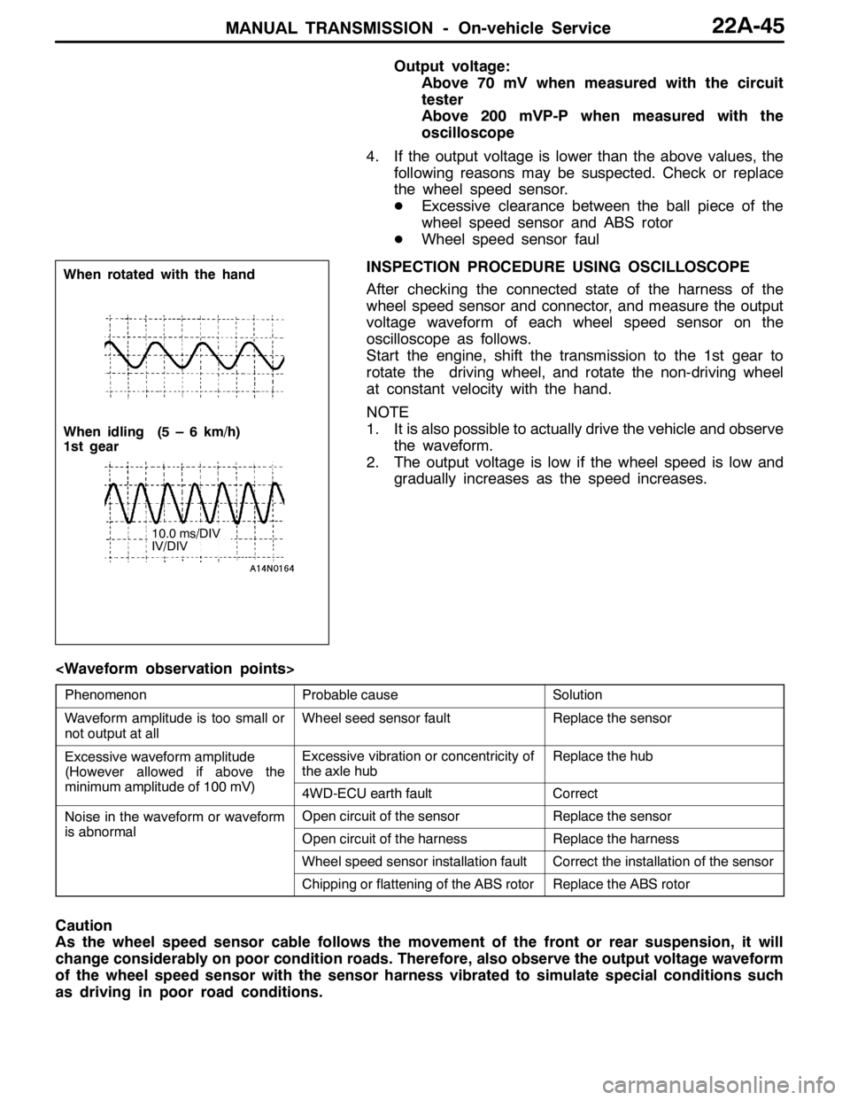
INSPECTION PROCEDURE USING OSCILLOSCOPE
After checking the connected state of the harness of the
wheel speed sensor and connector, and measure the output
voltage waveform of each wheel speed sensor on the
oscilloscope as follows.
Start the engine, shift the transmission to the 1st gear to
rotate the driving wheel, and rotate the non-driving wheel
at constant velocity with the hand.
NOTE
1. It is also possible to actually drive the vehicle and observe
the waveform.
2. The output voltage is low if the wheel speed is low and
gradually increases as the speed increases.
PhenomenonProbable causeSolution
Waveform amplitude is too small or
not output at allWheel seed sensor faultReplace the sensor
Excessive waveform amplitude
(However allowed if above the
iilit df100V)
Excessive vibration or concentricity of
the axle hubReplace the hub
(
minimum amplitude of 100 mV)4WD-ECU earth faultCorrect
Noise in the waveform or waveform
ibl
Open circuit of the sensorReplace the sensor
is abnormalOpen circuit of the harnessReplace the harness
Wheel speed sensor installation faultCorrect the installation of the sensor
Chipping or flattening of the ABS rotorReplace the ABS rotor
Caution
As the wheel speed sensor cable follows the movement of the front or rear suspension, it will
change considerably on poor condition roads. Therefore, also observe the output voltage waveform
of the wheel speed sensor with the sensor harness vibrated to simulate special conditions such
as driving in poor road conditions.
When rotated with the hand
When idling (5 – 6 km/h)
1st gear
10.0 ms/DIV
IV/DIV
Page 954 of 1449

REAR AXLE -Special Tools/Troubleshooting 27B-8
NumberNameO.D.mm
BoxMB990551Box–
CBaseMB990989Base–
ABCBase
MB990990Tool A25A
Tool
MB990991Tool B28
ToolMB990992Tool C31
Installer adapterBrass bar
Bar (one-touch type) AB
C
Toolbox
Tool numberO.D.mmTool numberO.D.mm
AMB99092639AMB99093363.5
MB99092745MB99093467.5
MB99092849.5MB99093571.5
MB99092951MB99093675.5
MB99093054MB99093779
MB99093157BMB990938-
MB99093261CMB990939-
TROUBLESHOOTING
BASIC TROUBLESHOOTING CONDITIONS
Refer to GROUP 00 – How to Use Troubleshooting/Inspection Service Points.
NOTE
Before starting the troubleshooting procedure, make sure that the following items have been checked
okay.
DThe correct steering wheel has been properly installed in the neutral position of the steering column
shaft.
DTire and wheel sizes are correct with correct specifications. Inflation pressure, balance, and wear
conditions are okay.
DWheel alignment is correct.
DThe engine, suspension, and other parts have not been remodeled so as to affect the AYC system.
DIAGNOSIS FUNCTION
READING THE DIAGNOSIS CODES
Read the diagnosis code using MUT-IIor ACD mode indicator
lamp. (Refer to GROUP 00 – How to Use Troubleshooting/
Inspection Service Points.)
NOTE
Connect the MUT-IIto the 16-pin diagnosis connector.
Page 1011 of 1449
WHEEL AND TYRE -Troubleshooting31-3
TROUBLESHOOTING
SymptomProbable causeRemedyReference page
Rapid wear at
shouldersUnder-inflation
or lack of rotationAdjust the tyre
pressure.31-6
Rapid wear at
centreOver-inflation or
lack of rotation
Cracked treadsUnder-inflationAdjust the tyre
pressure.31-6
Wear on one
sideExcessive
camberInspect the
camber.Refer to
GROUP 33A -
On-vehicle
Service.
Feathered edgeIncorrect toe-inAdjust the toe-in.
Bald spotsUnbalanced
wheelAdjust the
imbalanced
wheels.31-4
Scalloped wearLack of rotation of tyres or worn or
out-of-alignment suspensionRotate the tyres
and check the
front suspension
alignment.Refer to
GROUP 33A -
On-vehicle
Service.