2007 MITSUBISHI LANCER EVOLUTION Warning
[x] Cancel search: WarningPage 663 of 1449

MPI -On-vehicle Service13A-131
COMPONENT LOCATION
NameSymbolNameSymbol
A/C relayJFuel pump relay 1, 2Q
A/C switchTFuel pump relay 3H
Air flow sensor (integrated intake air tempera-
ture sensor and barometric pressure sensor)OFuel pump resistorH
Camshaft position sensorNIdle speed control servo (stepper motor)G
Crank angle sensorKIgnition coil (integrated power transister)M
Detonation sensorEInjectorC
Diagnosis connectorSOxygen sensor (front)L
EGR control solenoid valveDOxygen sensor (rear)X
Engine control relayIPower steering fluid pressure switchA
Engine coolant temperature sensorNResistor (for injector)H
Engine warning lamp (check engine lamp)RSecondary air control solenoid valveD
Engine-ECUUThrottle position sensorG
Fan motor relayJVehicle speed sensorF
Fuel pressure control solenoid valveBWaste gate solenoid valveP
ABCDEFGHIJK
LMNOP
QRSTU
Page 734 of 1449

ENGINE ELECTRICAL -Charging System16-2
CHARGING SYSTEM
GENERAL INFORMATION
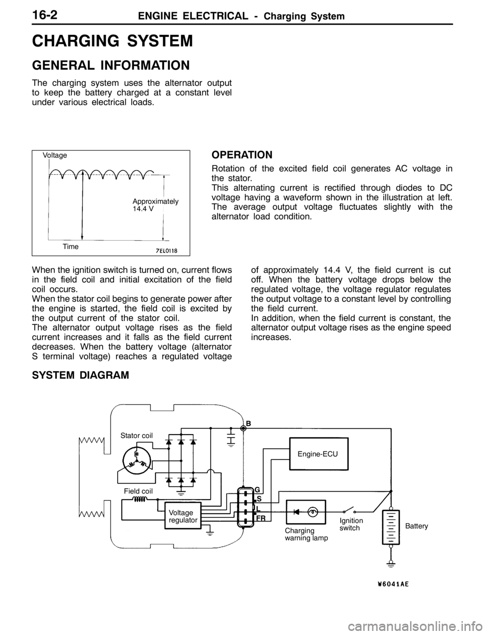
The charging system uses the alternator output
to keep the battery charged at a constant level
under various electrical loads.
OPERATION
Rotation of the excited field coil generates AC voltage in
the stator.
This alternating current is rectified through diodes to DC
voltage having a waveform shown in the illustration at left.
The average output voltage fluctuates slightly with the
alternator load condition.
When the ignition switch is turned on, current flows
in the field coil and initial excitation of the field
coil occurs.
When the stator coil begins to generate power after
the engine is started, the field coil is excited by
the output current of the stator coil.
The alternator output voltage rises as the field
current increases and it falls as the field current
decreases. When the battery voltage (alternator
S terminal voltage) reaches a regulated voltageof approximately 14.4 V, the field current is cut
off. When the battery voltage drops below the
regulated voltage, the voltage regulator regulates
the output voltage to a constant level by controlling
the field current.
In addition, when the field current is constant, the
alternator output voltage rises as the engine speed
increases.
SYSTEM DIAGRAM
Stator coil
Field coil
Voltage
regulatorEngine-ECU
Charging
warning lampIgnition
switchBattery B
G
L
FRS
Voltage
Time
Approximately
14.4 V
Page 737 of 1449

ENGINE ELECTRICAL -Charging System16-5
(6) Reconnect the negative battery cable.
(7) Connect a tachometer or the MUT-II.
(Refer to GROUP 11 - On-vehicle Service.)
(8) Leave the hood open.
(9) Start the engine.
(10)With the engine running at 2,500 r/min, turn
the headlamps and other lamps on and off
to adjust the alternator load so that the value
displayed on the ammeter is slightly above 30
A.
Adjust the engine speed by gradually
decreasing it until the value displayed on the
ammeter is 30 A. Take a reading of the value
displayed on the voltmeter at this time.
Limit: max. 0.3 V
NOTE
When the alternator output is high and the value
displayed on the ammeter does not decrease
until 30 A, set the value to 40 A. Read the
value displayed on the voltmeter at this time.
When the value range is 40 A, the limit is max.
0.4 V.(11) If the value displayed on the voltmeter is above
the limit value, there is probably a malfunction
in the alternator output wire, so check the wiring
between the alternator “B” terminal and the
battery (+) terminal (including fusible link).
If a terminal is not sufficiently tight or if the
harness has become discolored due to
overheating, repair and then test again.
(12)After the test, run the engine at idle.
(13)Turn off all lamps and the ignition switch.
(14)Remove the tachometer or the MUT-II.
(15)Disconnect the negative battery cable.
(16)Disconnect the ammeter and voltmeter.
(17)Connect the alternator output wire to the
alternator “B” terminal.
(18)Connect the negative battery cable.
OUTPUT CURRENT TEST
Charging warning lampVoltmeter
Ammeter
Ignition switch
Alternator relayLoad
Battery
Engine-ECUAlternatorFR
L
S
G
+ -+-
B
Page 742 of 1449

ENGINE ELECTRICAL -Charging System16-10
EXAMPLES OF ABNORMAL WAVEFORMS
NOTE
1. The size of the waveform patterns differs largely, depending on the adjustment of the variable knob
on the analyzer.
2. Identification of abnormal waveforms is easier when there is a large output current (regulator is not
operating). (Waveforms can be observed when the headlamps are illuminated.)
3. Check the conditions of the charging warning lamp (illuminated/not illuminated). Also, check the charging
system totally.
Abnormal waveformsProblem
causeAbnormal waveformsProblem
cause
Example 1Open diodeExample 4Short in
stator coil
Example 2Short in diodeExample 5Open
supplementa-
ry diode
Example 3Broken wire
in stator coil
At this time, the charging warning lamp
is illuminated.
ALTERNATOR
REMOVAL AND INSTALLATION
Caution
If the vehicle is equipped with the Brembo disc brake, during maintenance, take care not to contact
the parts or tools to the caliper because the paint of caliper will be scratched.
Pre-removal and Post-installation Operation
DUnder Cover Removal and Installation (Refer to GROUP 51 - Front Bumper.)
DDrive Belt Tension Check (Refer to GROUP 11A - On-vehicle Service.)
DStrut Tower Bar Removal and Installation (Refer to GROUP 42.)
DCrossmember Bar Removal and Installation (Refer to GROUP 32 - Engine Roll Stopper, Centermember.)
DFront Exhaust Pipe Assembly Removal and Installation (Refer to GROUP 15.)
Page 810 of 1449

22A-2
MANUAL
TRANSMISSION
CONTENTS
GENERAL 3.................................
Outline of Changes 3...........................
GENERAL INFORMATION 3..................
SERVICE SPECIFICATION 3..................
LUBRICANTS 3..............................
SPECIAL TOOLS 4...........................
TROUBLESHOOTING
ON-VEHICLE SERVICE 40....................
Transmission Oil Check 40......................
Transmission Oil Replacement 40................
Transfer Oil Check 40..........................
Transfer Oil Replacement 40....................
Fluid Check
Bleeding
Hydraulic Pressure Check
Wheel Speed Sensor Output Voltage
Measurement
TRANSMISSION CONTROL* 46...............
TRANSFER ASSEMBLY 49...................
TRANSMISSION ASSEMBLY 52...............
4WD-ECU
SENSOR, SWITCH AND RELAY
AYC> 56.....................................
HYDRAULIC UNIT Refer to GROUP27B.......
WARNING REGARDING SERVICING OF SUPPLEMENTAL RESTRAINT SYSTEM (SRS) EQUIPPED VEHICLES
WARNING!
(1) Improper service or maintenance of any component of the SRS, or any SRS-related component, can lead to personal
injury or death to service personnel (from inadvertent firing of the air bag) or to driver and passenger (from rendering
the SRS inoperative).
(2) Service or maintenance of any SRS component or SRS-related component must be performed only at an authorized
MITSUBISHI dealer.
(3) MITSUBISHI dealer personnel must thoroughly review this manual, and especially its GROUP 52B - Supplemental
Restraint System (SRS) before beginning any service or maintenance of any component of the SRS or any SRS-related
component.
NOTE
The SRS includes the following components: SRS-ECU, SRS warning lamp, air bag module, clock spring, and interconnecting
wiring. Other SRS-related components (that may have to be removed/installed in connection with SRS service or maintenance) are
indicated in the table of contents by an asterisk (*).
Page 819 of 1449

MANUAL TRANSMISSION - Troubleshooting
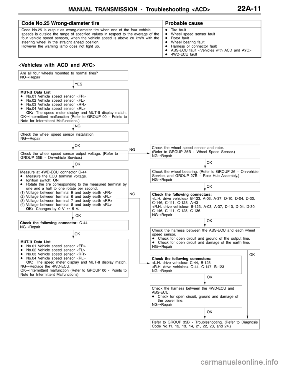
Code No.25 Wrong-diameter tireProbable cause
Code No.25 is output as wrong-diameter tire when one of the four vehicle
speeds is outside the range of specified values in respect to the average of the
four vehicle speed sensors, when the vehicle speed is above 20 km/h with the
steering wheel in the straight ahead position.
However the warning lamp does not light up.DTire fault
DWheel speed sensor fault
DRotor fault
DWheel bearing fault
DHarness or connector fault
DABS-ECU fault
D4WD-ECU fault
OK NG
OK
Check the following connector:C-44
NG→Repair
Check the following connectors:
NG→Repair OKYES
OK
OK
Check the wheel speed sensor and rotor.
(Refer to GROUP 35B - Wheel Speed Sensor.)
NG→Repair
Check the wheel speed sensor output voltage. (Refer to
GROUP 35B - On-vehicle Service.)OK
Check the wheel speed sensor installation.
NG→Repair
NG
OK
Check the wheel beearing. (Refer to GROUP 26 - On-vehicle
Service, and GROUP 27B - Rear Hub Assembly.)
NG→Repair
OK
Check the following connectors:
C-146, C-111, C-128, A-43
C-146, C-111, C-128, C-136
NG→Repair NG
MUT-IIData List
DNo.01 Vehicle speed sensor
DNo.02 Vehicle speed sensor
DNo.03 Vehicle speed sensor
DNo.04 Vehicle speed sensor
OK:The speed meter display and MUT-IIdisplay match.
OK→Intermittent malfunction (Refer to GROUP 00 - Points to
Note for Intermittent Malfunctions.)
Measure at 4WD-ECU connector C-44.
DMeasure the ECU terminal voltage.
DIgnition switch: ON
DRotate the tire corresponding to the measured terminal by
one and a half to one rotate per second.
(1) Voltage between terminal 9 and body earth
(2) Voltage between terminal 6 and body earth
(3) Voltage between terminal 7 and body earth
(4) Voltage between terminal 8 and body earth
OK:Changes by 0 V↔5V.
MUT-IIData List
DNo.01 Vehicle speed sensor
DNo.02 Vehicle speed sensor
DNo.03 Vehicle speed sensor
DNo.04 Vehicle speed sensor
OK:The speed meter display and MUT-IIdisplay match.
NG→Replace the 4WD-ECU.
OK→Intermittent malfunction (Refer to GROUP 00 - Points to
Note for Intermittent Malfunctions)
Refer to GROUP 35B - Troubleshooting. (Refer to Diagnosis
Code No.11, 12, 13, 14, 21, 22, 23, and 24.)
Are all four wheels mounted to normal tires?
NO→Repair
Check the harness between the ABS-ECU and each wheel
speed sensor.
DCheck for open circuit and ground of the output line.
DCheck for open circuit and damage of the earth line.
NG→Repair
OK
Check the harness between the 4WD-ECU and
ABS-ECU.
DCheck for open circuit, ground and damage of
the power line.
NG→RepairOK
Page 821 of 1449

MANUAL TRANSMISSION - Troubleshooting
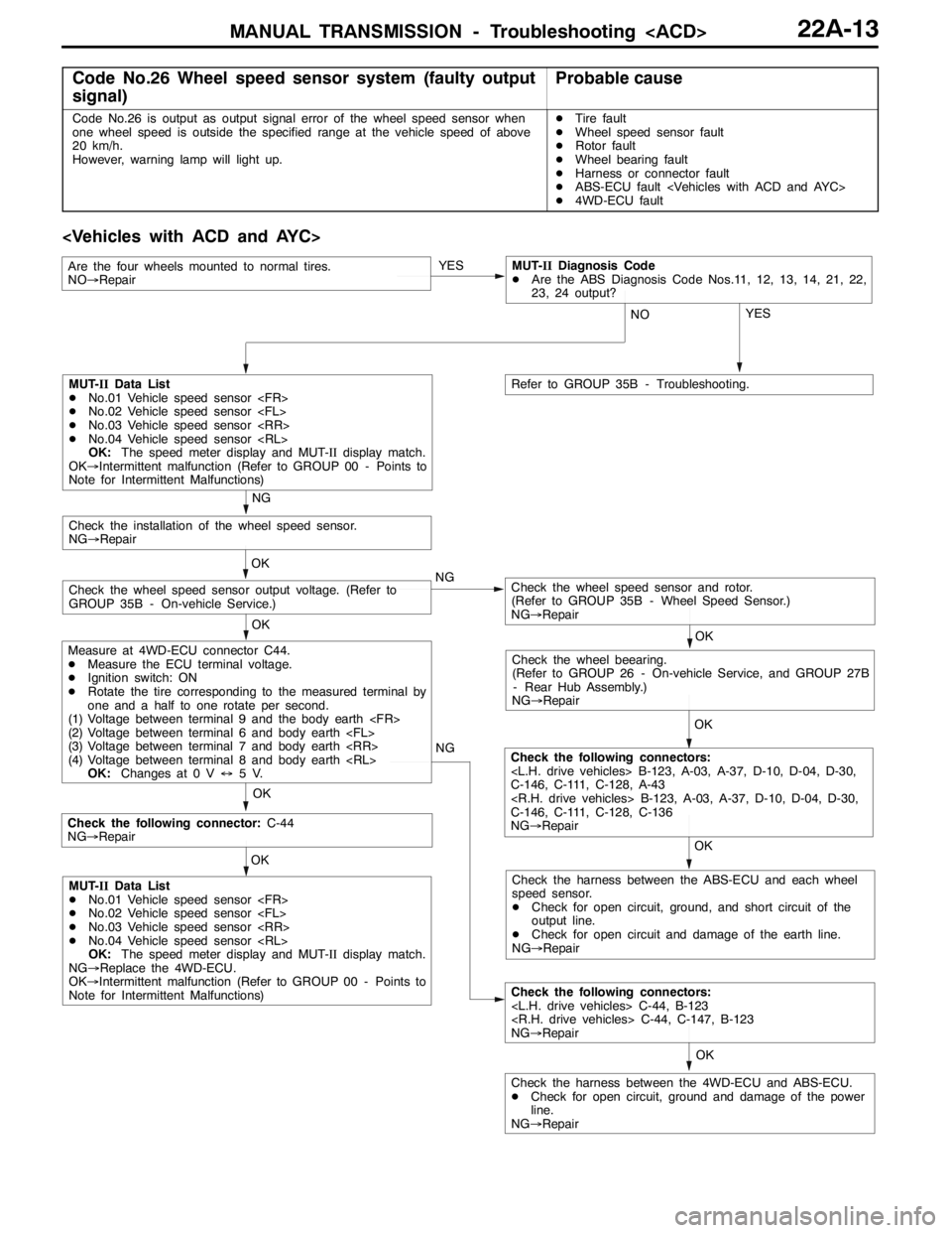
Code No.26 Wheel speed sensor system (faulty output
signal)Probable cause
Code No.26 is output as output signal error of the wheel speed sensor when
one wheel speed is outside the specified range at the vehicle speed of above
20 km/h.
However, warning lamp will light up.DTire fault
DWheel speed sensor fault
DRotor fault
DWheel bearing fault
DHarness or connector fault
DABS-ECU fault
D4WD-ECU fault
OK NG
OK
Check the following connector:C-44
NG→Repair
Check the following connectors:
NG→Repair OK
Check the harness between the 4WD-ECU and ABS-ECU.
DCheck for open circuit, ground and damage of the power
line.
NG→RepairYES
OK OK
Check the wheel speed sensor and rotor.
(Refer to GROUP 35B - Wheel Speed Sensor.)
NG→RepairCheck the wheel speed sensor output voltage. (Refer to
GROUP 35B - On-vehicle Service.)OK
Check the installation of the wheel speed sensor.
NG→Repair
NG
OK
Check the wheel beearing.
(Refer to GROUP 26 - On-vehicle Service, and GROUP 27B
- Rear Hub Assembly.)
NG→Repair
OK
Check the following connectors:
C-146, C-111, C-128, A-43
C-146, C-111, C-128, C-136
NG→Repair NG
MUT-IIData List
DNo.01 Vehicle speed sensor
DNo.02 Vehicle speed sensor
DNo.03 Vehicle speed sensor
DNo.04 Vehicle speed sensor
OK:The speed meter display and MUT-IIdisplay match.
OK→Intermittent malfunction (Refer to GROUP 00 - Points to
Note for Intermittent Malfunctions)
Measure at 4WD-ECU connector C44.
DMeasure the ECU terminal voltage.
DIgnition switch: ON
DRotate the tire corresponding to the measured terminal by
one and a half to one rotate per second.
(1) Voltage between terminal 9 and the body earth
(2) Voltage between terminal 6 and body earth
(3) Voltage between terminal 7 and body earth
(4) Voltage between terminal 8 and body earth
OK:Changes at 0 V↔5V.
MUT-IIData List
DNo.01 Vehicle speed sensor
DNo.02 Vehicle speed sensor
DNo.03 Vehicle speed sensor
DNo.04 Vehicle speed sensor
OK:The speed meter display and MUT-IIdisplay match.
NG→Replace the 4WD-ECU.
OK→Intermittent malfunction (Refer to GROUP 00 - Points to
Note for Intermittent Malfunctions)Check the harness between the ABS-ECU and each wheel
speed sensor.
DCheck for open circuit, ground, and short circuit of the
output line.
DCheck for open circuit and damage of the earth line.
NG→Repair YES
NO
Refer to GROUP 35B - Troubleshooting.
Are the four wheels mounted to normal tires.
NO→RepairMUT-IIDiagnosis Code
DAre the ABS Diagnosis Code Nos.11, 12, 13, 14, 21, 22,
23, 24 output?
Page 835 of 1449

MANUAL TRANSMISSION - Troubleshooting
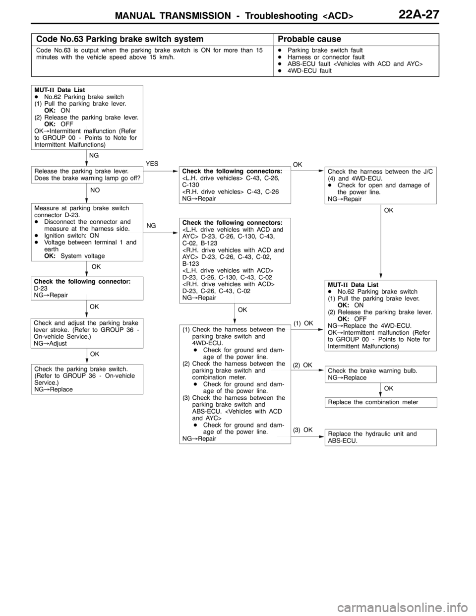
Code No.63 Parking brake switch systemProbable cause
Code No.63 is output when the parking brake switch is ON for more than 15
minutes with the vehicle speed above 15 km/h.DParking brake switch fault
DHarness or connector fault
DABS-ECU fault
D4WD-ECU fault
OK
NG
YES
NG
(3) OK(1) OKReplace the hydraulic unit and
ABS-ECU.
MUT-IIData List
DNo.62 Parking brake switch
(1) Pull the parking brake lever.
OK:ON
(2) Release the parking brake lever.
OK:OFF
OK→Intermittent malfunction (Refer
to GROUP 00 - Points to Note for
Intermittent Malfunctions)
Measure at parking brake switch
connector D-23.
DDisconnect the connector and
measure at the harness side.
DIgnition switch: ON
DVoltage between terminal 1 and
earth
OK:System voltage
Release the parking brake lever.
Does the brake warning lamp go off?
OK
Check the following connector:
D-23
NG→Repair
OK
Replace the combination meter
OK
Check the brake warning bulb.
NG→ReplaceCheck the parking brake switch.
(Refer to GROUP 36 - On-vehicle
Service.)
NG→Replace
OK
Check and adjust the parking brake
lever stroke. (Refer to GROUP 36 -
On-vehicle Service.)
NG→Adjust
MUT-IIData List
DNo.62 Parking brake switch
(1) Pull the parking brake lever.
OK:ON
(2) Release the parking brake lever.
OK:OFF
NG→Replace the 4WD-ECU.
OK→Intermittent malfunction (Refer
to GROUP 00 - Points to Note for
Intermittent Malfunctions) NOOK
Check the following connectors:
C-130
NG→Repair
Check the following connectors:
C-02, B-123
B-123
D-23, C-26, C-130, C-43, C-02
D-23, C-26, C-43, C-02
NG→Repair
(2) OK
(1) Check the harness between the
parking brake switch and
4WD-ECU.
DCheck for ground and dam-
age of the power line.
(2) Check the harness between the
parking brake switch and
combination meter.
DCheck for ground and dam-
age of the power line.
(3) Check the harness between the
parking brake switch and
ABS-ECU.
DCheck for ground and dam-
age of the power line.
NG→Repair
OK
Check the harness between the J/C
(4) and 4WD-ECU.
DCheck for open and damage of
the power line.
NG→Repair