2007 MITSUBISHI LANCER EVOLUTION Warning
[x] Cancel search: WarningPage 541 of 1449

MPI -Troubleshooting13A-9
TROUBLESHOOTING
DIAGNOSIS TROUBLESHOOTING FLOW
Refer to GROUP 00 - How to Use Troubleshooting/Inspection
Service Point.
NOTE
If the engine-ECU is replaced, the immobilizer-ECU and
ignition key should be replaced together with it.
DIAGNOSIS FUNCTION
ENGINE WARNING LAMP (CHECK ENGINE LAMP)
If an abnormality occurs in any of the following items related
to the MPI system, the engine warning lamp will illuminate
or flash. If the lamp remains illuminated or if the lamp
illuminates while the engine is running, check the diagnosis
code output.
However, the warning lamp will illuminate as bulb check for
5 seconds whenever the ignition switch is turned to the ON
position.
Engine warning lamp inspection items
Code No.Diagnosis item
-Engine-ECU
P0100Air flow sensor system
P0105Barometric pressure sensor system
P0110Intake air temprature sensor system
P0115Engine coolant temperature sensor system
P0120Throttle position sensor system
P0130Oxygen sensor (front) system
P0135Oxygen sensor heater (front) system
P0136Oxygen sensor (rear) system
P0141Oxygen sensor heater (rear) system
P0201No.1 injector system
P0202No.2 injector system
P0203No.3 injector system
P0204No.4 injector system
P0325Detonation sensor system
P0335Crank angle sensor system
P0340Camshaft position sensor system
P0403EGR control solenoid valve system
Engine warning lamp
(check engine lamp)
Page 542 of 1449

MPI -TroubleshootingMPI -Troubleshooting13A-10
Code No. Diagnosis item
P0443Purge control solenoid valve system
P0500Vehicle speed sensor system
P0505Idle speed control system
P0551Power steering fluid pressure switch
P1104Waste gate solenoid valve system
P1105Fuel pressure control solenoid valve system
NOTE
If the engine warning lamp illuminates because of a malfunction of the engine-ECU, communication between
MUT-IIand the engine-ECU is impossible. In this case, the diagnosis code cannot be read.
METHOD OF READING AND ERASING DIAGNOSIS
CODES
Refer to GROUP 00 - How to Use Troubleshooting/Inspection
Service Points.
INSPECTION USING MUT-IIDATA LIST AND ACTUATOR
TESTING
1. Carry out inspection by means of the data list and the
actuator test function. If there is an abnormality, check
and repair the chassis harnesses and components.
2. After repairing, re-check using the MUT-IIand check that
the abnormal input and output have returned to normal
as a result of the repairs.
3. Erase the diagnosis code memory.
4. Remove the MUT-II, and then start the engine again and
carry out a road test to confirm that the problem has
disappeared.
Page 584 of 1449

MPI -Troubleshooting13A-52
INSPECTION CHART FOR TROUBLE SYMPTOMS
Inspection
procedureCheck itemsReference page
1Communication between MUT-IIand entire system is not possible.13A-54
2Only communication between MUT-IIand engine-ECU is not possible.13A-55
3Engine warning lamp does not illuminate immediately after ignition switch is set to ON position.13A-56
4Engine warning lamp stays illuminated and does not turn OFF.13A-57
5Starting disabled (Starter does not rotate.)13A-58
6Starting disabled (Starter rotates but initial combustion does not occur.)13A-59
7Starting disabled (Initial combustion occurs but is incomplete.)13A-61
Improper starting (Starting time is long.)
8Unstable idling (Rough idling, hunting)13A-63
Inappropriate idling speed (High or low idling speed)
Engine stalls (Die out) during idling
9Engine stalls when starting travel. (Pass out)13A-66
10Engine stalls during deceleration13A-67
11Pulsation (Hesitation, sag)13A-68
Poor acceleration
Stumbling
Surging
12Shock during acceleration13A-70
13Shock during deceleration13A-71
14Knocking13A-72
15Deviation of ignition interval13A-73
16Run on (Dieseling)13A-74
17Abnormal odor, white smoke, black smoke, high CO or HC concentration when idling13A-75
18Battery dies13A-77
19Overheating13A-79
20Abnormal radiator fan motor rotation13A-80
21A/C ineffective13A-81
22Engine-ECU power supply, engine control relay, ignition switch-IG1 system13A-82
23Fuel pump system13A-85
24Radiator fan control relay system13A-87
25Condenser fan relay system13A-89
26A/C switch system13A-92
27A/C compressor relay system13A-93
28A/C load signal system13A-95
29Secondary air control solenoid valve system13A-96
30Intercooler water spray circuit system13A-97
31Intercooler water spray lamp system13A-99
32Ignition coil (integrated power transistor) system13A-100
Page 587 of 1449

MPI -Troubleshooting13A-55
Inspection Procedure 2
Only communication between MUT-IIand engine-ECU is
not possible.
Probable cause
Causes shown on right are suspected.DIgnition switch malfunction
DEngine control relay malfunction
DEngine-ECU malfunction
NG
Replace the engine-ECU.
OK
Check the trouble symptoms.OKIntermittent malfunction
(Refer to GROUP 00 - Points to Note
for Intermittent Malfunctions.)
OK
Check the harness between the
diagnosis connector and engine-ECU.
DCheck for disconnection,
short-circuit and damage of the
communication cable.
DCheck for disconnection,
short-circuit and damage of the
signal cable.NG
Repair
OK
Check the following connectors:
C-26, C-130, C-118, C-108, C-28
Repair
Check the engine warning lamp.
DIgnition switch: ON
OK:Engine warning lamp is
illuminated.NGCheck the Inspection Procedure 22:
Engine-ECU power supply, engine
control relay, ignition switch-IG system.
NOTE
If the problem symptom does not disappear in the vehicle with MMCS after carrying out the above - mentioned
inspection procedure, there may be a malfunction in the multi - center display.
Page 588 of 1449

MPI -Troubleshooting13A-56
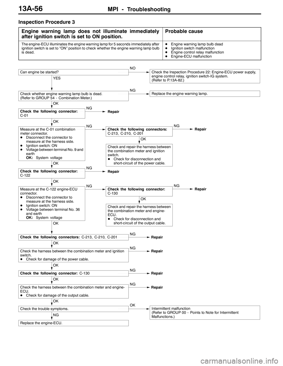
Inspection Procedure 3
Engine warning lamp does not illuminate immediately
after ignition switch is set to ON position.
Probable cause
The engine-ECU illuminates the engine warning lamp for 5 seconds immediately after
ignition switch is set to “ON” position to check whether the engine warning lamp bulb
is dead.DEngine warning lamp bulb dead
DIgnition switch malfunction
DEngine control relay malfunction
DEngine-ECU malfunction
NG
Replace the engine-ECU.
OK
Check the trouble symptoms.OKIntermittent malfunction
(Refer to GROUP 00 - Points to Note for Intermittent
Malfunctions.)
OK
Check the harness between the combination meter and engine-
ECU.
DCheck for damage of the output cable.NG
Repair
OK
Check the following connector:C-130NG
Repair
OK
Check the harness between the combination meter and ignition
switch.
DCheck for damage of the power cable.NG
Repair
OK
Check the following connectors:C-213, C-210, C-201NG
Repair
OK
Check and repair the harness between
the combination meter and engine-
ECU.
DCheck for disconnection and
short-circuit of the output cable.
OK
Measure at the C-122 engine-ECU
connector.
DDisconnect the connector to
measure at the harness side.
DIgnition switch: ON
DVoltage between terminal No. 36
and earth
OK:System voltageNGCheck the following connector:
C-130NG
Repair
OK
Check the following connector:
C-122NG
Repair
OK
Check and repair the harness between
the combination meter and ignition
switch.
DCheck for disconnection and
short-circuit of the power cable.
OK
Measure at the C-01 combination
meter connector.
DDisconnect the connector to
measure at the harness side.
DIgnition switch: ON
DVoltage between terminal No. 9 and
earth
OK:System voltageNGCheck the following connectors:
C-213, C-210, C-201NG
Repair
OK
Check the following connector:
C-01NG
Repair
YES
Check whether engine warning lamp bulb is dead.
(Refer to GROUP 54 - Combination Meter.)NGReplace the engine warning lamp.
Can engine be started?NOCheck the Inspection Procedure 22: Engine-ECU power supply,
engine control relay, ignition switch-IG system.
(Refer to P.13A-82.)
Page 589 of 1449

MPI -Troubleshooting13A-57
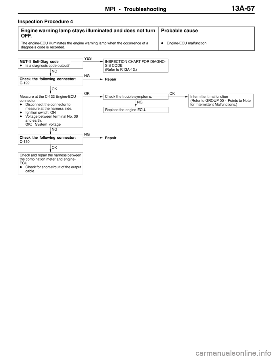
Inspection Procedure 4
Engine warning lamp stays illuminated and does not turn
OFF.
Probable cause
The engine-ECU illuminates the engine warning lamp when the occurrence of a
diagnosis code is recorded.DEngine-ECU malfunction
OK
Check and repair the harness between
the combination meter and engine-
ECU.
DCheck for short-circuit of the output
cable.
NG
Check the following connector:
C-130NG
Repair
NG
Replace the engine-ECU.
OK
Measure at the C-122 Engine-ECU
connector.
DDisconnect the connector to
measure at the harness side.
DIgnition switch: ON
DVoltage between terminal No. 36
and earth.
OK:System voltageOKCheck the trouble symptoms.OKIntermittent malfunction
(Refer to GROUP 00 - Points to Note
for Intermittent Malfunctions.)
NO
Check the following connector:
C-122NG
Repair
MUT-IISelf-Diag code
DIs a diagnosis code output?YESINSPECTION CHART FOR DIAGNO-
SIS CODE
(Refer to P.13A-12.)
Page 591 of 1449

MPI -Troubleshooting13A-59
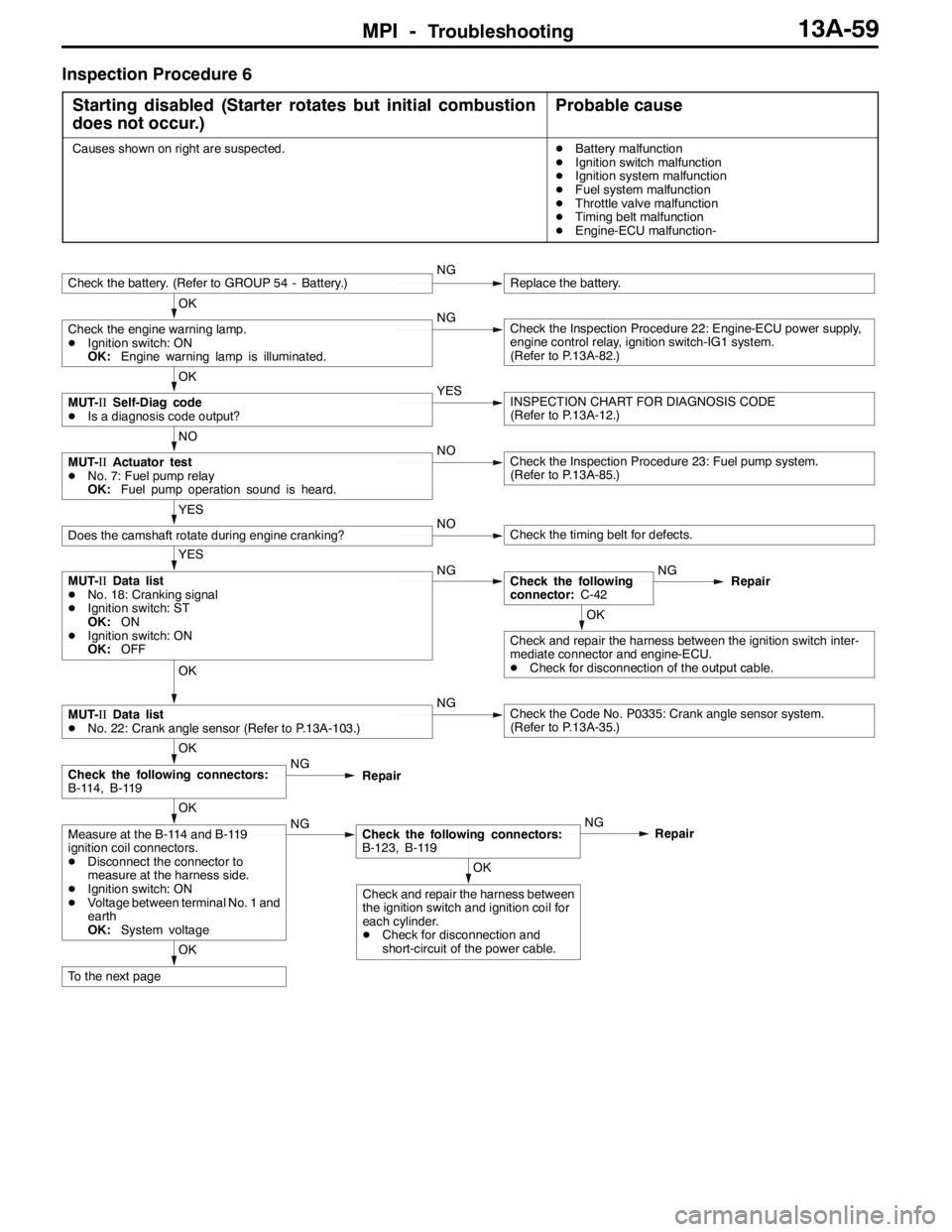
Inspection Procedure 6
Starting disabled (Starter rotates but initial combustion
does not occur.)
Probable cause
Causes shown on right are suspected.DBattery malfunction
DIgnition switch malfunction
DIgnition system malfunction
DFuel system malfunction
DThrottle valve malfunction
DTiming belt malfunction
DEngine-ECU malfunction-
OK
To the next page
OK
Check and repair the harness between
the ignition switch and ignition coil for
each cylinder.
DCheck for disconnection and
short-circuit of the power cable.
OK
Measure at the B-114 and B-119
ignition coil connectors.
DDisconnect the connector to
measure at the harness side.
DIgnition switch: ON
DVoltage between terminal No. 1 and
earth
OK:System voltageNGCheck the following connectors:
B-123, B-119NG
Repair
OK
Check the following connectors:
B-114, B-119NG
Repair
OK
MUT-IIData list
DNo. 22: Crank angle sensor (Refer to P.13A-103.)NGCheck the Code No. P0335: Crank angle sensor system.
(Refer to P.13A-35.)
OK
Check and repair the harness between the ignition switch inter-
mediate connector and engine-ECU.
DCheck for disconnection of the output cable.
YES
MUT-IIData list
DNo. 18: Cranking signal
DIgnition switch: ST
OK:ON
DIgnition switch: ON
OK:OFFNGCheck the following
connector:C-42NG
Repair
YES
Does the camshaft rotate during engine cranking?NOCheck the timing belt for defects.
NO
MUT-IIActuator test
DNo. 7: Fuel pump relay
OK:Fuel pump operation sound is heard.NOCheck the Inspection Procedure 23: Fuel pump system.
(Refer to P.13A-85.)
OK
MUT-IISelf-Diag code
DIs a diagnosis code output?YESINSPECTION CHART FOR DIAGNOSIS CODE
(Refer to P.13A-12.)
OK
Check the engine warning lamp.
DIgnition switch: ON
OK:Engine warning lamp is illuminated.NGCheck the Inspection Procedure 22: Engine-ECU power supply,
engine control relay, ignition switch-IG1 system.
(Refer to P.13A-82.)
Check the battery. (Refer to GROUP 54 - Battery.)NGReplace the battery.
Page 642 of 1449

MPI -Troubleshooting13A-110
Terminal No.Normal condition Check condition (Engine condition) Check item
12Power supplyIgnition switch: “ON”System voltage
25
19Air flow sensor reset
signal
Engine: Idle operation0-1V
signal
Engine speed: 3,000 r/min6-9V
21Fan controllerRadiator fan is not operating0 - 0.3 V
Radiator fan is operating0.7 V or more
22Fuel pump relay 2Ignition switch: “ON”System voltage
Engine: Idle operation1 V or less
24A/C load signalDEngine:
Idle operation
DA/C switch: ON
(A/C compressor
runs)DOutdoor air
sensor ambient
temperature:
18_C or more
DA/C setting
temperature:
Minimum
temperature
DA/C air volume:
Maximum1 V or less
DA/C setting
temperature:
indoor
temperature
DA/C air volume:
MinimumSystem voltage
32Condenser fan motor
relay (HI)Fan inactive state
(Engine coolant temperature: 90_C or less)System voltage
Fan high-speed rotation state
(Engine coolant temperature: 105_C or more)1 V or less
33Alternator G terminalDEngine: After warm-up, idle operation
DRadiator fan: Not operating
DHeadlamp: OFF→ON
DStop lamp: OFF→ON
DRear defogger switch: OFF→ONVoltage increases by
0.2 - 3.5 V
34Condenser fan motor
relay (LOW)Fan inactive state
(Engine coolant temperature: 90_C or less)System voltage
Fan low-speed rotation state (Engine coolant
temperature: 95 - 100_C or more)1 V or less
35Intercooler water
spraylamp
Ignition switch: “ON”System voltage
spraylamp
Ignition switch: “LOCK” (OFF)1 V or less
36Engine warning lampIgnition switch: “LOCK” (OFF)→“ON”1 V or less→System
voltage (After several se-
conds have elapsed)