Page 962 of 1449

REAR AXLE -On-vehicle Service27B-16
DATA LIST REFERENCE TABLE
For check, refer to GROUP 22.
ACTUATOR TEST REFERENCE TABLE
For check, refer to GROUP 22.
CHECK AT 4WD-ECU TERMINALS
For check, refer to GROUP 22.
ON-VEHICLE SERVICE
REAR AXLE TOTAL BACKLASH CHECK
1. Park the vehicle on a flat, level surface.
2. Move the transmission control lever to the neutral position.
Apply the parking brake. Raise the vehicle on a jack.
3. Turn the companion flange clockwise as far as it will go.
Make the mating mark on the dust cover of the companion
flange and on the differential carrier.
4. Turn the companion flange anti-clockwise as far as it
will go, and measure the amount of distance the mating
marks moved.
Limit: 6 mm
5. If the backlash exceeds the limit value, replace the
differential carrier assembly.
GEAR OIL LEVEL CHECK
1. Remove the filler plug.
2. Check that the gear oil level is within the specified range
from the bottom end of the filler plug hole.
3. If the gear oil level exceeds the standard value, add the
specified gear oil up to the bottom end of the filler plug
hole.
Specified gear oil:
Hypoid gear oil
MITSUBISHI Genuine Gear Oil Part No. 8149630
EX, CASTROL HYPOY LS (GL-5, SAE 90),
SHELL-LSD (GL-5, SAE 80W - 90) or equivalent
4. Fit the filler plug and tighten it to the specified torque.
Tightening torque: 49±9 N·m
Mating marks
Upper
limit
Lower
limit
Gear oil
8mm
Page 976 of 1449

REAR AXLE -Drive Shaft27B-30
REMOVAL SERVICE POINTS
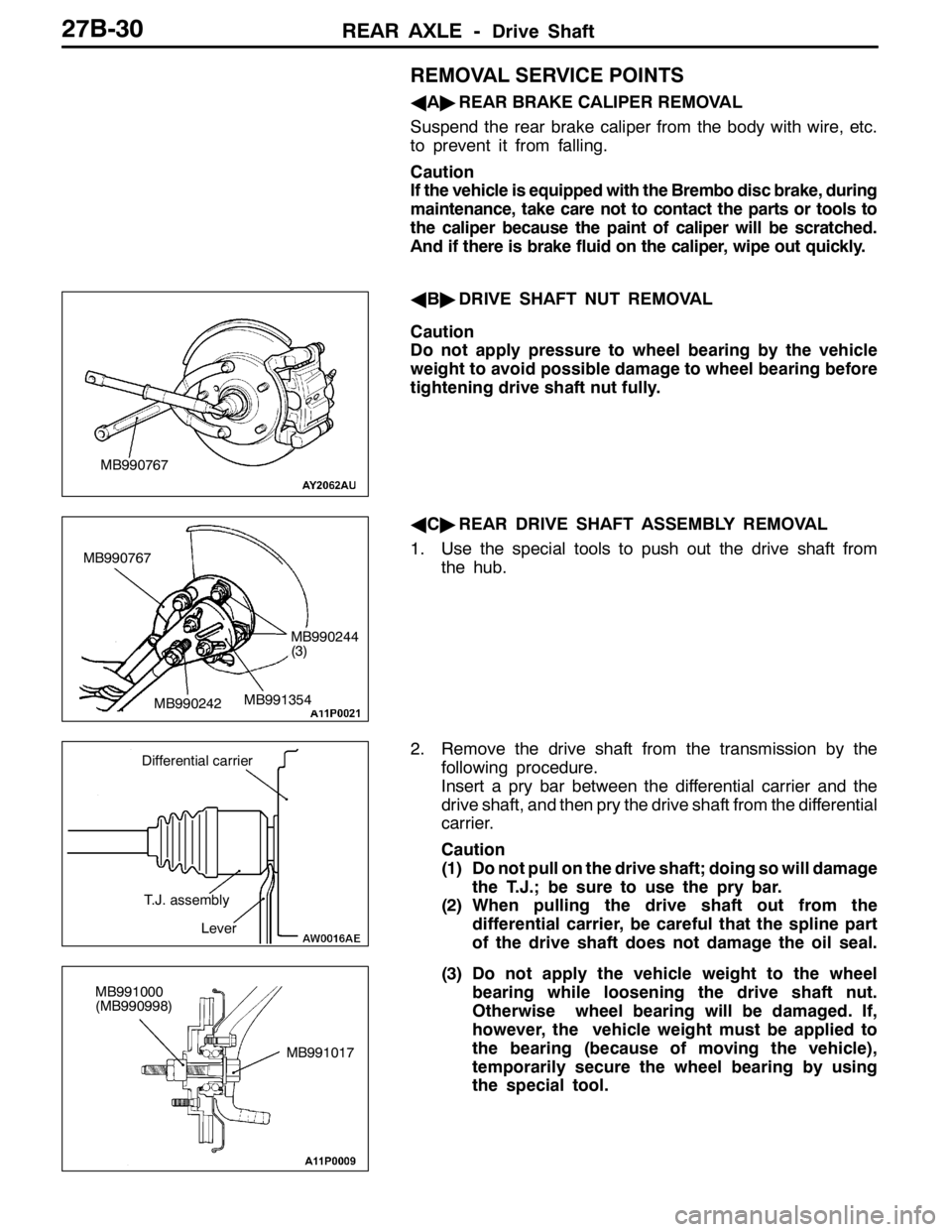
AA"REAR BRAKE CALIPER REMOVAL
Suspend the rear brake caliper from the body with wire, etc.
to prevent it from falling.
Caution
If the vehicle is equipped with the Brembo disc brake, during
maintenance, take care not to contact the parts or tools to
the caliper because the paint of caliper will be scratched.
And if there is brake fluid on the caliper, wipe out quickly.
AB"DRIVE SHAFT NUT REMOVAL
Caution
Do not apply pressure to wheel bearing by the vehicle
weight to avoid possible damage to wheel bearing before
tightening drive shaft nut fully.
AC"REAR DRIVE SHAFT ASSEMBLY REMOVAL
1. Use the special tools to push out the drive shaft from
the hub.
2. Remove the drive shaft from the transmission by the
following procedure.
Insert a pry bar between the differential carrier and the
drive shaft, and then pry the drive shaft from the differential
carrier.
Caution
(1) Do not pull on the drive shaft; doing so will damage
the T.J.; be sure to use the pry bar.
(2) When pulling the drive shaft out from the
differential carrier, be careful that the spline part
of the drive shaft does not damage the oil seal.
(3) Do not apply the vehicle weight to the wheel
bearing while loosening the drive shaft nut.
Otherwise wheel bearing will be damaged. If,
however, the vehicle weight must be applied to
the bearing (because of moving the vehicle),
temporarily secure the wheel bearing by using
the special tool.
MB990767
MB990767
MB990242MB991354
MB990244
(3)
Differential carrier
T.J. assembly
Lever
MB991017 MB991000
(MB990998)
Page 980 of 1449
REAR AXLE -Drive Shaft27B-34
"BAT.J. BOOT BAND (SMALL)/T.J. BOOT BAND
(LARGE) INSTALLATION
Set the T.J. boot bands at the specified distance in order
to adjust the amount of air inside the T.J. boot, and then
tighten the T.J. boot bands securely.
Standard value (A): 90±3mm
INSPECTION
DCheck the drive shaft for damage, bending or corrosion.
DCheck the drive shaft spline part for wear or damage.
DCheck the spider assembly for roller rotation, wear or
corrosion.
DCheck the groove inside T.J. case for wear or corrosion.
DCheck the boots for deterioration, damage or cracking.
DCheck the dust cover for damage or deterioration.
B.J. BOOT (RESIN BOOT) REPLACEMENT
Refer to GROUP26 Front Axle-Drive shaft.
A
Page 997 of 1449

REAR AXLE -Differential Carrier 27B-51
REMOVAL SERVICE POINT
AA"SCREWS REMOVAL
1. Check out the alignment marks.
2. Loosen a uniform amount little by little the screws securing
differential case A to B.
3. Separate differential case B from differential case A and
remove their components.
Keep the removed spring plates, friction plates, and friction
discs organized in the order of removal and for right and
left use.
INSTALLATION SERVICE POINTS
"AADIFFERENTIAL CASE B INSTALLATION
Before starting the assembly procedure, perform the following
steps to adjust dimensional differences (clutch plate friction
force) in the axial direction of the components inside the
differential case and axial clearance of the differential side
gear.
1. Place friction discs (two each) and friction plates (three
each) one on top of another as illustrated and, using
a micrometer, measure the thickness of each of the right
and left assemblies. Select different discs and plates so
that the difference between the right and left assemblies
falls within the specified range.
Standard value: 0 – 0.05 mm
NOTE
If a new part is used, note that the friction disc comes
in two thicknesses: 1.6 mm and 1.7 mm.
2. Measure the thickness of each of the right and left spring
plates.
3. Assemble the pressure ring internal parts (pinion shaft
and pressure ring), friction plates, and friction discs and,
using a micrometer, measure the overall width.
NOTE
When taking measurements, press the assembly from
both sides so that the pinion shaft makes a positive contact
with the groove in the pressure ring.
4. Find value (A) which is the thickness measured in step
(3) added to the thickness of two spring plates.
A
Groove
Page 1015 of 1449

32-1
POWER PLANT
MOUNT
CONTENTS
GENERAL INFORMATION 2..................
SPECIAL TOOL 3............................
ENGINE MOUNTING 4........................TRANSMISSION MOUNTING 5................
ENGINE ROLL STOPPER, CENTERMEMBER
6 ............................................
CROSSMEMBER* 8..........................
WARNING REGARDING SERVICING OF SUPPLEMENTAL RESTRAINT SYSTEM (SRS) EQUIPPED VEHICLES
WARNING!
(1) Improper service or maintenance of any component of the SRS, or any SRS-related component, can lead to personal
injury or death to service personnel (from inadvertent firing of the air bag) or to driver and passenger (from rendering
the SRS inoperative).
(2) Service or maintenance of any SRS component or SRS-related component must be performed only at an authorized
MITSUBISHI dealer.
(3) MITSUBISHI dealer personnel must thoroughly review this manual, and especially its GROUP 52B - Supplemental
Restraint System (SRS) before beginning any service or maintenance of any component of the SRS or any SRS-related
component.
NOTE
The SRS includes the following components: SRS-ECU, SRS warning lamp, air bag module, clock spring, and interconnecting
wiring. Other SRS-related components (that may have to be removed/installed in connection with SRS service or maintenance) are
indicated in the table of contents by an asterisk (*).
Page 1018 of 1449
POWER PLANT MOUNT - Engine Mounting32-4
ENGINE MOUNTING
REMOVAL AND INSTALLATION
Caution
*: Indicates parts which should be initially tightened, and then fully tightened after placing the
vehicle horizontally and loading the full weight of the engine on the vehicle body.
Pre-removal and Post-installation Operation
DUnder Cover Removal and Installation (Refer to
GROUP 51 - Front Bumper.)DRaise the engine and transmission assembly until
its weight is not applied to the insulator, and support
it securely.
98±10 N·m*
67±7 N·m*
1
2
12±2 N·m
3 44
Removal steps
1. Power steering pressure hose as-
sembly
2. Engine mounting connecting bolt3. Engine mounting bracket
"AA4. Engine mounting insulator
INSTALLATION SERVICE POINT
"AAENGINE MOUNTING INSULATOR INSTALLATION
Arrow marks on the engine mount insulator should face the
shown direction.
NOTE
Disregard F and R stamped as a shared part.
Engine sideEngine side
Engine mounting insulator
>
Page 1019 of 1449

POWER PLANT MOUNT - Transmission Mounting32-5
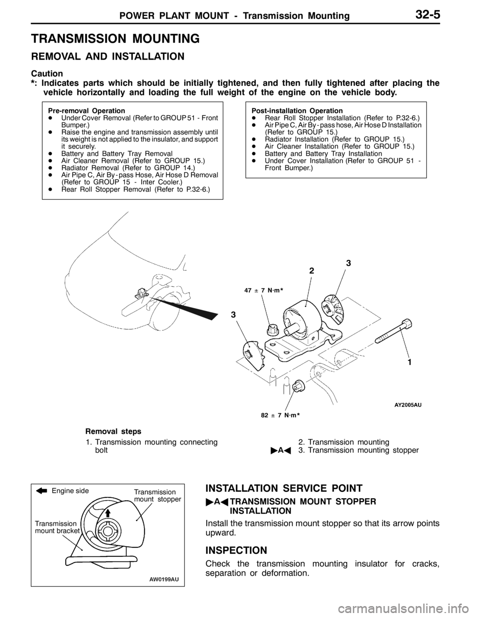
TRANSMISSION MOUNTING
REMOVAL AND INSTALLATION
Caution
*: Indicates parts which should be initially tightened, and then fully tightened after placing the
vehicle horizontally and loading the full weight of the engine on the vehicle body.
Pre-removal Operation
DUnder Cover Removal (Refer to GROUP 51 - Front
Bumper.)
DRaise the engine and transmission assembly until
its weight is not applied to the insulator, and support
it securely.
DBattery and Battery Tray Removal
DAir Cleaner Removal (Refer to GROUP 15.)
DRadiator Removal (Refer to GROUP 14.)
DAir Pipe C, Air By - pass Hose, Air Hose D Removal
(Refer to GROUP 15 - Inter Cooler.)
DRear Roll Stopper Removal (Refer to P.32-6.)Post-installation Operation
DRear Roll Stopper Installation (Refer to P.32-6.)
DAir Pipe C, Air By - pass hose, Air Hose D Installation
(Refer to GROUP 15.)
DRadiator Installation (Refer to GROUP 15.)
DAir Cleaner Installation (Refer to GROUP 15.)
DBattery and Battery Tray Installation
DUnder Cover Installation (Refer to GROUP 51 -
Front Bumper.)
47±7 N·m*
3
3
82±7 N·m*
2
1
Removal steps
1. Transmission mounting connecting
bolt2. Transmission mounting
"AA3. Transmission mounting stopper
INSTALLATION SERVICE POINT
"AATRANSMISSION MOUNT STOPPER
INSTALLATION
Install the transmission mount stopper so that its arrow points
upward.
INSPECTION
Check the transmission mounting insulator for cracks,
separation or deformation.
Engine side
Transmission
mount bracketTransmission
mount stopper
Page 1052 of 1449

BASIC BRAKE SYSTEM -On-vehicle Service35A-10
BLEEDING
Caution
Specified brake fluid: DOT3 or DOT4
Always use the specified brake fluid. Avoid using a
mixture of the specified brake fluid and other fluid.
MASTER CYLINDER BLEEDING
The master cylinder used has no check valve, so if bleeding
is carried out by the following procedure, bleeding of air from
the brake pipeline will become easier. (When brake fluid is
not contained in the master cylinder.)
1. Fill the reserve tank with brake fluid.
2. Keep the brake pedal depressed.
3. Have another person cover the master cylinder outlet
with a finger.
4. With the outlet still closed, release the brake pedal.
5. Repeat steps 2 - 4 three or four times to fill the inside
of the master cylinder with brake fluid.
BREMBO DISC BRAKE BLEEDING
Caution
Take care not to contact the parts or tools to the caliper
because the paint of caliper will be scratched. And if
there is brake fluid on the caliper, wipe out quickly.
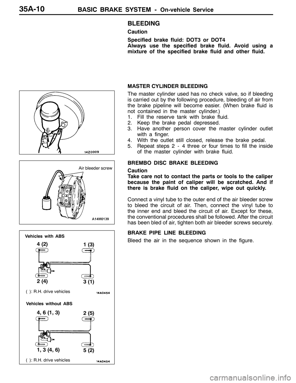
Connect a vinyl tube to the outer end of the air bleeder screw
to bleed the circuit of air. Then, connect the vinyl tube to
the inner end and bleed the circuit of air. Except for these,
the conventional procedures shall be followed. After the circuit
has been bled of air, tighten both air bleeder screws securely.
BRAKE PIPE LINE BLEEDING
Bleed the air in the sequence shown in the figure.
Air bleeder screw
( ): R.H. drive vehicles
4 (2)
1 (3)
2 (4)
3 (1)
( ): R.H. drive vehicles
4, 6 (1, 3)
2 (5)
1, 3 (4, 6)
5 (2)
Vehicles with ABS
Vehicles without ABS