Page 853 of 1449
MANUAL TRANSMISSION - On-vehicle Service22A-45
Output voltage:
Above 70 mV when measured with the circuit
tester
Above 200 mVP-P when measured with the
oscilloscope
4. If the output voltage is lower than the above values, the
following reasons may be suspected. Check or replace
the wheel speed sensor.
DExcessive clearance between the ball piece of the
wheel speed sensor and ABS rotor
DWheel speed sensor faul
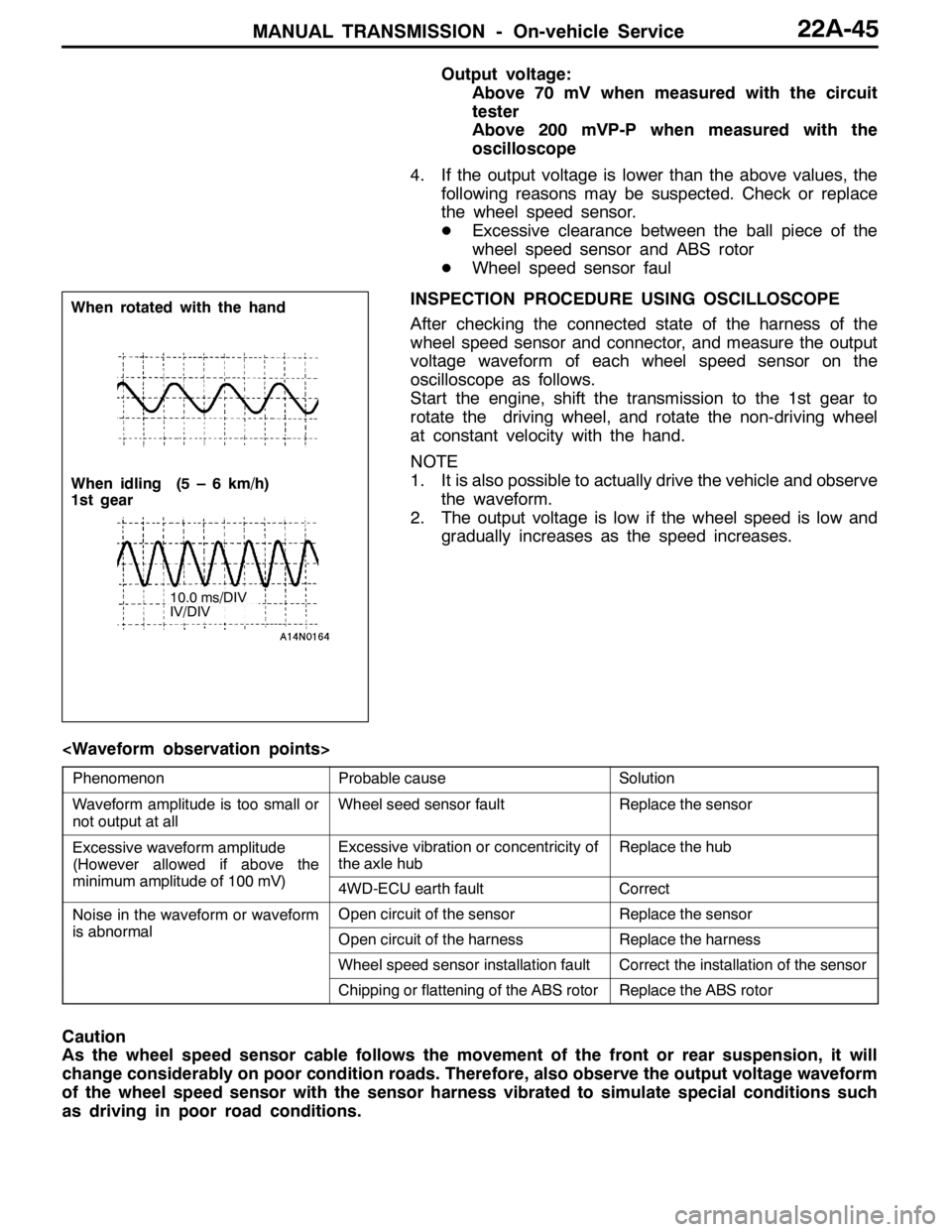
INSPECTION PROCEDURE USING OSCILLOSCOPE
After checking the connected state of the harness of the
wheel speed sensor and connector, and measure the output
voltage waveform of each wheel speed sensor on the
oscilloscope as follows.
Start the engine, shift the transmission to the 1st gear to
rotate the driving wheel, and rotate the non-driving wheel
at constant velocity with the hand.
NOTE
1. It is also possible to actually drive the vehicle and observe
the waveform.
2. The output voltage is low if the wheel speed is low and
gradually increases as the speed increases.
PhenomenonProbable causeSolution
Waveform amplitude is too small or
not output at allWheel seed sensor faultReplace the sensor
Excessive waveform amplitude
(However allowed if above the
iilit df100V)
Excessive vibration or concentricity of
the axle hubReplace the hub
(
minimum amplitude of 100 mV)4WD-ECU earth faultCorrect
Noise in the waveform or waveform
ibl
Open circuit of the sensorReplace the sensor
is abnormalOpen circuit of the harnessReplace the harness
Wheel speed sensor installation faultCorrect the installation of the sensor
Chipping or flattening of the ABS rotorReplace the ABS rotor
Caution
As the wheel speed sensor cable follows the movement of the front or rear suspension, it will
change considerably on poor condition roads. Therefore, also observe the output voltage waveform
of the wheel speed sensor with the sensor harness vibrated to simulate special conditions such
as driving in poor road conditions.
When rotated with the hand
When idling (5 – 6 km/h)
1st gear
10.0 ms/DIV
IV/DIV
Page 854 of 1449
MANUAL TRANSMISSION - Transmission Control22A-46
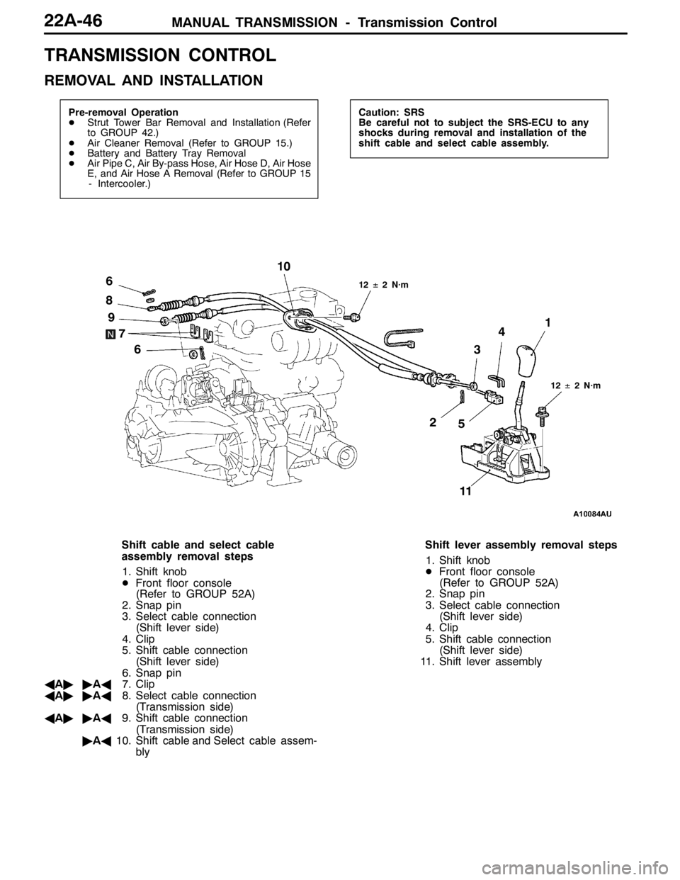
TRANSMISSION CONTROL
REMOVAL AND INSTALLATION
Pre-removal Operation
DStrut Tower Bar Removal and Installation (Refer
to GROUP 42.)
DAir Cleaner Removal (Refer to GROUP 15.)
DBattery and Battery Tray Removal
DAir Pipe C, Air By-pass Hose, Air Hose D, Air Hose
E, and Air Hose A Removal (Refer to GROUP 15
- Intercooler.)Caution: SRS
Be careful not to subject the SRS-ECU to any
shocks during removal and installation of the
shift cable and select cable assembly.
12±2 N·m
34
21
5 6
7 8
6 910
12±2 N·m
11
Shift cable and select cable
assembly removal steps
1. Shift knob
DFront floor console
(Refer to GROUP 52A)
2. Snap pin
3. Select cable connection
(Shift lever side)
4. Clip
5. Shift cable connection
(Shift lever side)
6. Snap pin
AA""AA7. Clip
AA""AA8. Select cable connection
(Transmission side)
AA""AA9. Shift cable connection
(Transmission side)
"AA10. Shift cable and Select cable assem-
blyShift lever assembly removal steps
1. Shift knob
DFront floor console
(Refer to GROUP 52A)
2. Snap pin
3. Select cable connection
(Shift lever side)
4. Clip
5. Shift cable connection
(Shift lever side)
11. Shift lever assembly
Page 863 of 1449
MANUAL TRANSMISSION -4WD-ECU
with ACD and AYC>22A-55
4WD-ECU
AYC>
REMOVAL AND INSTALLATION
Pre-removal and Post-installation Operation
DCowl Side Trim Removal and Installation. (Refer to GROUP 52A - Trims.)
DFront floor Console Removal and Installation. (Refer to GROUP 52A - Floor Console.)
4.9�¶0.9 N��m
4WD-ECU
4.9�¶0.9 N��m
4WD-ECU
Page 933 of 1449
FRONT AXLE -On-vehicle Service26-5
ON-VEHICLE SERVICE
WHEEL BEARING AXIAL PLAY CHECK
1. Remove the disc brake caliper and suspend it with a
wire.
2. Remove the brake disc from the front hub.
3. Attach a dial gauge as shown in the illustration, and then
measure the axial play while moving the hub in the axial
direction.
Limit: 0.06 mm
4. If axial play exceeds the limit, replace the front hub
assembly.
HUB BOLT REPLACEMENT
1. Remove the caliper assembly and secure it with wire
so that it does not fall.
2. Remove the brake disc.
3. Use the special tools to remove the hub bolts.
4. Install the plain washer to the new hub bolt, and install
the bolt with a nut.
MB991618MB990767
Plain
washerMB990767
Page 935 of 1449
FRONT AXLE -Hub and Knuckle Assembly26-7
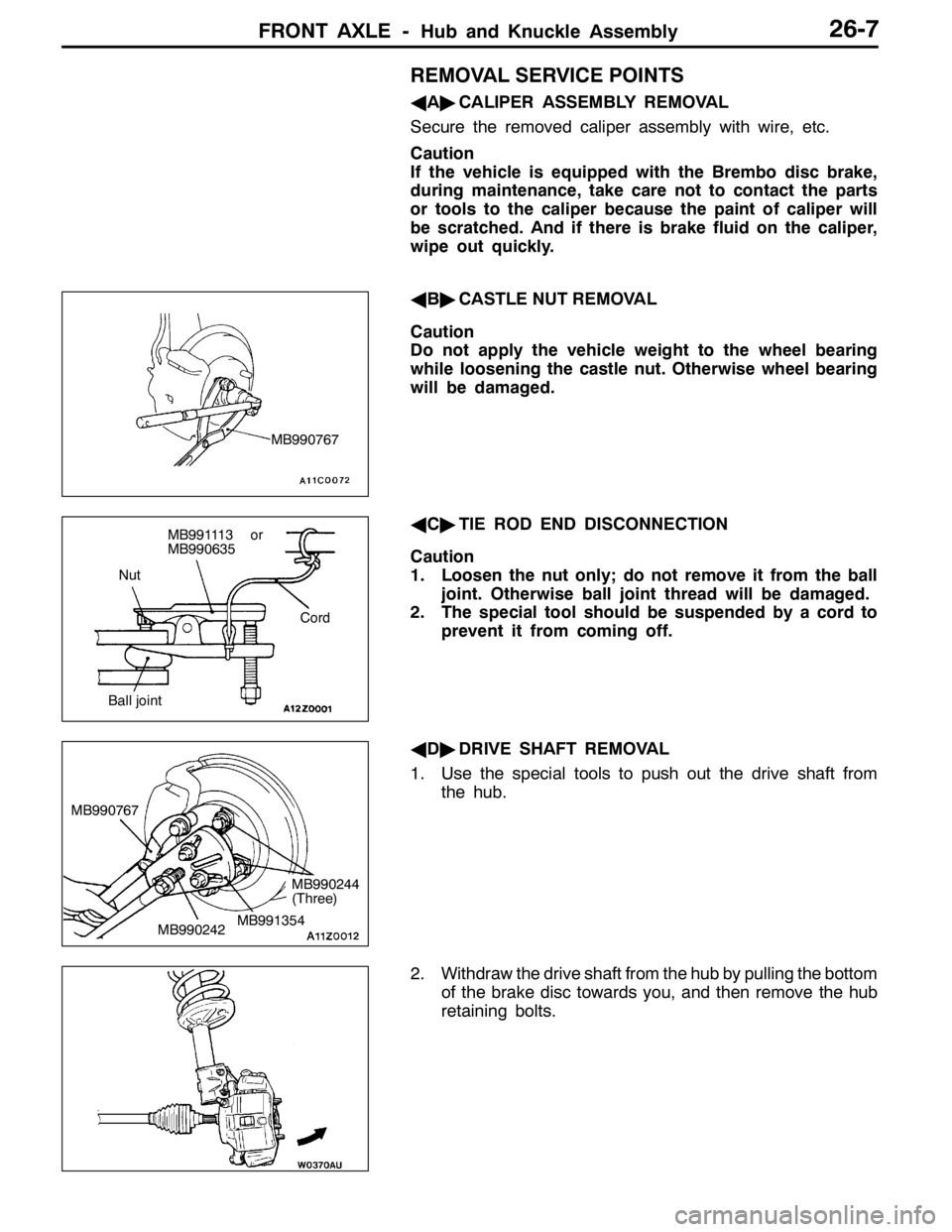
REMOVAL SERVICE POINTS
AA"CALIPER ASSEMBLY REMOVAL
Secure the removed caliper assembly with wire, etc.
Caution
If the vehicle is equipped with the Brembo disc brake,
during maintenance, take care not to contact the parts
or tools to the caliper because the paint of caliper will
be scratched. And if there is brake fluid on the caliper,
wipe out quickly.
AB"CASTLE NUT REMOVAL
Caution
Do not apply the vehicle weight to the wheel bearing
while loosening the castle nut. Otherwise wheel bearing
will be damaged.
AC"TIE ROD END DISCONNECTION
Caution
1. Loosen the nut only; do not remove it from the ball
joint. Otherwise ball joint thread will be damaged.
2. The special tool should be suspended by a cord to
prevent it from coming off.
AD"DRIVE SHAFT REMOVAL
1. Use the special tools to push out the drive shaft from
the hub.
2. Withdraw the drive shaft from the hub by pulling the bottom
of the brake disc towards you, and then remove the hub
retaining bolts.
MB990767
Nut
Cord
Ball joint
MB991113 or
MB990635
MB990242 MB990767MB991354
MB990244
(Three)
Page 936 of 1449
FRONT AXLE -Hub and Knuckle Assembly26-8
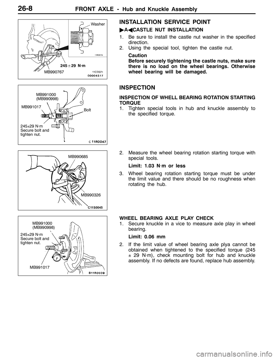
INSTALLATION SERVICE POINT
"AACASTLE NUT INSTALLATION
1. Be sure to install the castle nut washer in the specified
direction.
2. Using the special tool, tighten the castle nut.
Caution
Before securely tightening the castle nuts, make sure
there is no load on the wheel bearings. Otherwise
wheel bearing will be damaged.
INSPECTION
INSPECTION OF WHELL BEARING ROTATION STARTING
TORQUE
1. Tighten special tools in hub and knuckle assembly to
the specified torque.
2. Measure the wheel bearing rotation starting torque with
special tools.
Limit: 1.03 N·m or less
3. Wheel bearing rotation starting torque must be under
the limit value and there should be no roughness when
rotating the hub.
WHEEL BEARING AXLE PLAY CHECK
1. Secure knuckle in a vice to measure axle play in wheel
bearing.
Limit: 0.06 mm
2. If the limit value of wheel bearing axle plya cannot be
obtained when tightened to the specified torque (245
±29 N·m), check mounting bolt for hub and knuckle
assembly. If no defects are found, replace hub assembly.
MB990767
245±29 N·m
Washer
MB991000
(MB990998)
Bolt
245±29 N·m
Secure bolt and
tighten nut.
MB991017
MB990326
MB990685
MB991000
(MB990998)
245±29 N·m
Secure bolt and
tighten nut.
MB991017
Page 939 of 1449
FRONT AXLE -Drive Shaft26-11
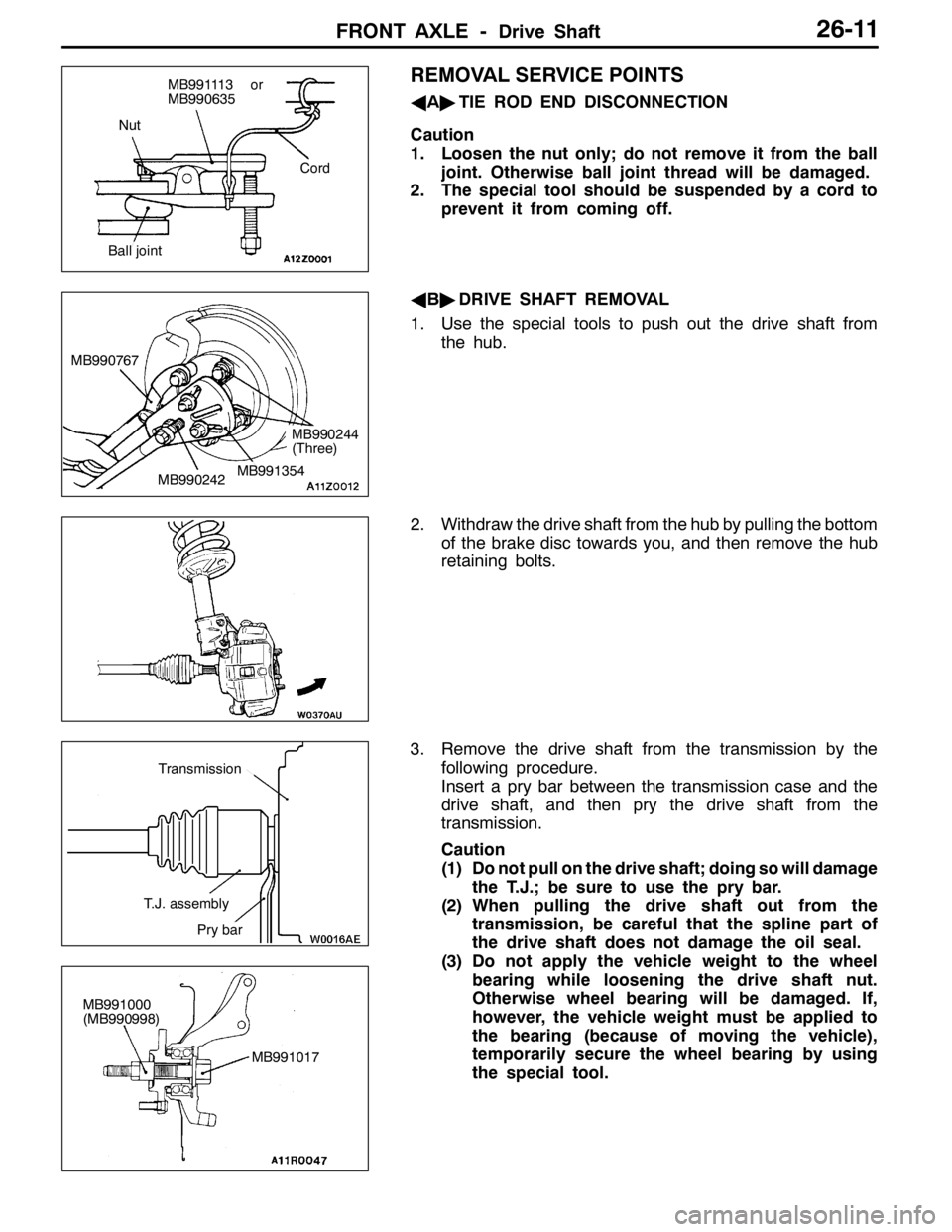
REMOVAL SERVICE POINTS
AA"TIE ROD END DISCONNECTION
Caution
1. Loosen the nut only; do not remove it from the ball
joint. Otherwise ball joint thread will be damaged.
2. The special tool should be suspended by a cord to
prevent it from coming off.
AB"DRIVE SHAFT REMOVAL
1. Use the special tools to push out the drive shaft from
the hub.
2. Withdraw the drive shaft from the hub by pulling the bottom
of the brake disc towards you, and then remove the hub
retaining bolts.
3. Remove the drive shaft from the transmission by the
following procedure.
Insert a pry bar between the transmission case and the
drive shaft, and then pry the drive shaft from the
transmission.
Caution
(1) Do not pull on the drive shaft; doing so will damage
the T.J.; be sure to use the pry bar.
(2) When pulling the drive shaft out from the
transmission, be careful that the spline part of
the drive shaft does not damage the oil seal.
(3) Do not apply the vehicle weight to the wheel
bearing while loosening the drive shaft nut.
Otherwise wheel bearing will be damaged. If,
however, the vehicle weight must be applied to
the bearing (because of moving the vehicle),
temporarily secure the wheel bearing by using
the special tool.
Nut
Cord
Ball joint
MB991113 or
MB990635
MB990242 MB990767MB991354
MB990244
(Three)
T.J. assembly
Pry bar
Transmission
MB991000
(MB990998)
MB991017
Page 940 of 1449
FRONT AXLE -Drive Shaft26-12
AC"OUTPUT SHAFT REMOVAL
Use the special tool to pull out the output shaft.
Caution
Do not damage the oil seal of the transmission by the
output shaft splines.
INSTALLATION SERVICE POINTS
"AAOUTPUT SHAFT/DRIVE SHAFT INSTALLATION
Caution
Do not damage the oil seal of the transmission by the
output shaft and drive shaft splines.
"BACASTLE NUT INSTALLATION
1. Be sure to install the castle nut washer in the specified
direction.
2. Using the special tool, tighten the castle nut.
Caution
Before securely tightening the castle nuts, make sure
there is no load on the wheel bearings. Otherwise
wheel bearing will be damaged.
Output shaft
MB991721
MB990767
245±29 N·m
Washer