2007 MITSUBISHI LANCER EVOLUTION ECU
[x] Cancel search: ECUPage 834 of 1449
MANUAL TRANSMISSION - Troubleshooting
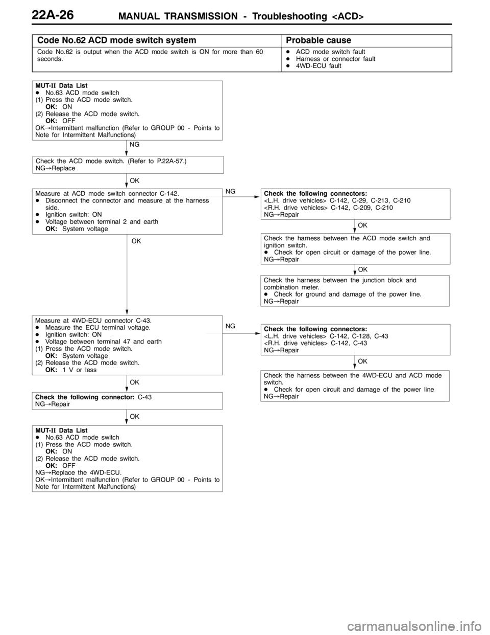
Code No.62 ACD mode switch systemProbable cause
Code No.62 is output when the ACD mode switch is ON for more than 60
seconds.DACD mode switch fault
DHarness or connector fault
D4WD-ECU fault
OK
OK
OK
NG
NG
MUT-IIData List
DNo.63 ACD mode switch
(1) Press the ACD mode switch.
OK:ON
(2) Release the ACD mode switch.
OK:OFF
OK→Intermittent malfunction (Refer to GROUP 00 - Points to
Note for Intermittent Malfunctions)
Check the ACD mode switch. (Refer to P.22A-57.)
NG→Replace
NG
OK
Check the following connectors:
NG→Repair
OK
Measure at ACD mode switch connector C-142.
DDisconnect the connector and measure at the harness
side.
DIgnition switch: ON
DVoltage between terminal 2 and earth
OK:System voltage
Measure at 4WD-ECU connector C-43.
DMeasure the ECU terminal voltage.
DIgnition switch: ON
DVoltage between terminal 47 and earth
(1) Press the ACD mode switch.
OK:System voltage
(2) Release the ACD mode switch.
OK:1 V or less
OK
Check the following connectors:
NG→Repair
OK
Check the harness between the junction block and
combination meter.
DCheck for ground and damage of the power line.
NG→Repair
Check the harness between the 4WD-ECU and ACD mode
switch.
DCheck for open circuit and damage of the power line
NG→Repair
Check the following connector:C-43
NG→Repair
Check the harness between the ACD mode switch and
ignition switch.
DCheck for open circuit or damage of the power line.
NG→Repair
MUT-IIData List
DNo.63 ACD mode switch
(1) Press the ACD mode switch.
OK:ON
(2) Release the ACD mode switch.
OK:OFF
NG→Replace the 4WD-ECU.
OK→Intermittent malfunction (Refer to GROUP 00 - Points to
Note for Intermittent Malfunctions)
Page 835 of 1449
MANUAL TRANSMISSION - Troubleshooting
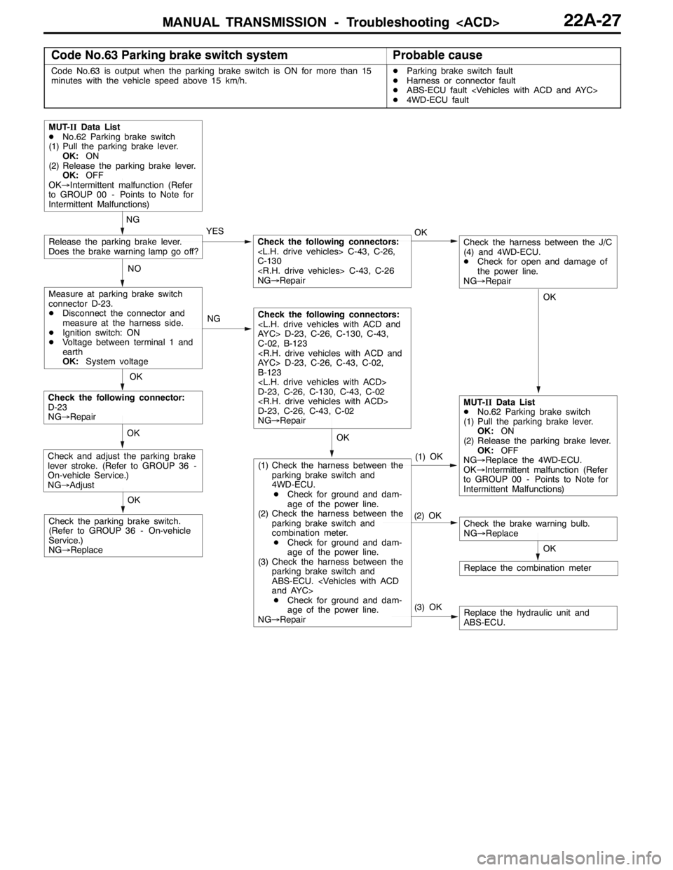
Code No.63 Parking brake switch systemProbable cause
Code No.63 is output when the parking brake switch is ON for more than 15
minutes with the vehicle speed above 15 km/h.DParking brake switch fault
DHarness or connector fault
DABS-ECU fault
D4WD-ECU fault
OK
NG
YES
NG
(3) OK(1) OKReplace the hydraulic unit and
ABS-ECU.
MUT-IIData List
DNo.62 Parking brake switch
(1) Pull the parking brake lever.
OK:ON
(2) Release the parking brake lever.
OK:OFF
OK→Intermittent malfunction (Refer
to GROUP 00 - Points to Note for
Intermittent Malfunctions)
Measure at parking brake switch
connector D-23.
DDisconnect the connector and
measure at the harness side.
DIgnition switch: ON
DVoltage between terminal 1 and
earth
OK:System voltage
Release the parking brake lever.
Does the brake warning lamp go off?
OK
Check the following connector:
D-23
NG→Repair
OK
Replace the combination meter
OK
Check the brake warning bulb.
NG→ReplaceCheck the parking brake switch.
(Refer to GROUP 36 - On-vehicle
Service.)
NG→Replace
OK
Check and adjust the parking brake
lever stroke. (Refer to GROUP 36 -
On-vehicle Service.)
NG→Adjust
MUT-IIData List
DNo.62 Parking brake switch
(1) Pull the parking brake lever.
OK:ON
(2) Release the parking brake lever.
OK:OFF
NG→Replace the 4WD-ECU.
OK→Intermittent malfunction (Refer
to GROUP 00 - Points to Note for
Intermittent Malfunctions) NOOK
Check the following connectors:
C-130
NG→Repair
Check the following connectors:
C-02, B-123
B-123
D-23, C-26, C-130, C-43, C-02
D-23, C-26, C-43, C-02
NG→Repair
(2) OK
(1) Check the harness between the
parking brake switch and
4WD-ECU.
DCheck for ground and dam-
age of the power line.
(2) Check the harness between the
parking brake switch and
combination meter.
DCheck for ground and dam-
age of the power line.
(3) Check the harness between the
parking brake switch and
ABS-ECU.
DCheck for ground and dam-
age of the power line.
NG→Repair
OK
Check the harness between the J/C
(4) and 4WD-ECU.
DCheck for open and damage of
the power line.
NG→Repair
Page 836 of 1449
MANUAL TRANSMISSION - Troubleshooting
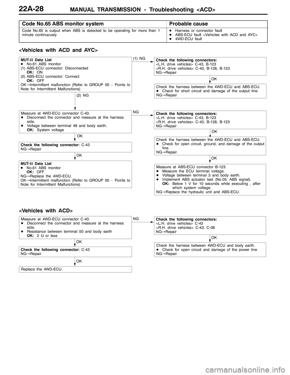
Code No.65 ABS monitor systemProbable cause
Code No.65 is output when ABS is detected to be operating for more than 1
minute continuously.DHarness or connector fault
DABS-ECU fault
D4WD-ECU fault
OK
(2) NG(1) NG
MUT-IIData List
DNo.61 ABS monitor
(1) ABS-ECU connector: Disconnected
OK:ON
(2) ABS-ECU connector: Connect
OK:OFF
OK→Intermittent malfunction (Refer to GROUP 00 - Points to
Note for Intermittent Malfunctions)
Check the following connectors:
NG→Repair
MUT-IIData List
DNo.61 ABS monitor
OK:OFF
NG→Replace the 4WD-ECU.
OK→Intermittent malfunction (Refer to GROUP 00 - Points to
Note for Intermittent Malfunctions)
OK
Check the following connectors:
NG→Repair
Check the harness between the 4WD-ECU and ABS-ECU.
DCheck for short circuit and damage of the output line.
NG→Repair
NG
OK
Measure at 4WD-ECU connector C-43.
DDisconnect the connector and measure at the harness
side.
DVoltage between terminal 49 and body earth.
OK:System voltage
OK
Check the harness between the 4WD-ECU and ABS-ECU.
DCheck for open circuit, ground, and damage of the output
line.
NG→Repair
Measure at ABS-ECU connector B-123.
DMeasure the ECU terminal voltage.
DVoltage between terminal 3 and body earth.
DImplement ABS actuator test (No.05: ABS signal).
OK:Below 1 V for 10 seconds while executing , after
which system voltage.
NG→Replace the hydraulic unit and ABS-ECU.
OK
Check the following connector:C-43
NG→Repair
OK
Check the following connectors:
NG→Repair
Check the harness between 4WD-ECU and body earth.
DCheck for open circuit and damage of the power line
NG→Repair
NG
OK
Measure at 4WD-ECU connector C-43.
DDisconnect the connector and measure at the harness
side.
DResistance between terminal 50 and body earth
OK:2Ωor less
OK
Replace the 4WD-ECU.
Check the following connector:C-43
NG→Repair
Page 837 of 1449
MANUAL TRANSMISSION - Troubleshooting
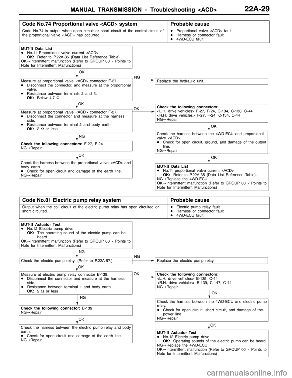
Code No.74 Proportional valve
Code No.74 is output when open circuit or short circuit of the control circuit of
the proportional valve
DHarness or connector fault
D4WD-ECU fault
OK
OK
OK
Replace the hydraulic unit.NG
NG
MUT-IIData List
DNo.11 Proportional valve current
OK:Refer to P.22A-35 (Data List Reference Table).
OK→Intermittent malfunction (Refer to GROUP 00 - Points to
Note for Intermittent Malfunctions)
MUT-IIData List
DNo.11 proportional valve current
OK:Refer to P.22A-35 (Data List Reference Table).
NG→Replace the 4WD-ECU.
OK→Intermittent malfunction (Refer to GROUP 00 - Points to
Note for Intermittent Malfunctions)
OK
Measure at proportional valve
DDisconnect the connector, and measure at the proportional
valve.
DResistance between terminals 2 and 3.
OK:Below 4.7Ω
Measure at proportional valve
DDisconnect the connector and measure at the harness
side.
DResistance between terminal 2 and body earth.
OK:2Ωor less
Check the harness between the proportional valve
body earth.
DCheck for open circuit and damage of the earth line.
NG→Repair
Check the following connectors:F-27, F-24
NG→Repair
OK
Check the following connectors:
NG→Repair
OK
Check the harness between the 4WD-ECU and proportional
valve
DCheck for open circuit, ground, and damage of the output
line.
NG→Repair
Code No.81 Electric pump relay systemProbable cause
Output when the coil circuit of the electric pump relay has open circuited or
short circuited.DElectric pump relay fault
DHarness or connector fault
D4WD-ECU fault
OK
OK
NG
Replace the electric pump relay.NG
NG
MUT-IIActuator Test
DNo.12 Electric pump drive
OK:The operating sound of the electric pump can be
heard.
OK→Intermittent malfunction (Refer to GROUP 00 - Points to
Note for Intermittent Malfunctions)
OK
Check the harness between the electric pump relay and body
earth.
DCheck for open circuit and damage of the earth line.
NG→Repair
Check the following connector:B-139
NG→Repair
OK
Check the following connectors:
NG→Repair
Check the electric pump relay. (Refer to P.22A-57.)
Measure at electric pump relay connector B-139.
DDisconnect the connector and measure at the harness
side.
DResistance between terminal 1 and body earth
OK:2Ωor less
MUT-IIActuator Test
DNo.12 Electric pump drive
OK:Operating sounds of the electric pump can be heard.
NG→Replace the 4WD-ECU.
OK→Intermittent malfunction (Refer to GROUP 00 - Points to
Note for Intermittent Malfunctions)
OK
Check the harness between the 4WD-ECU and electric pump
relay.
DCheck for open circuit, short circuit, and damage of the
power line.
NG→Repair
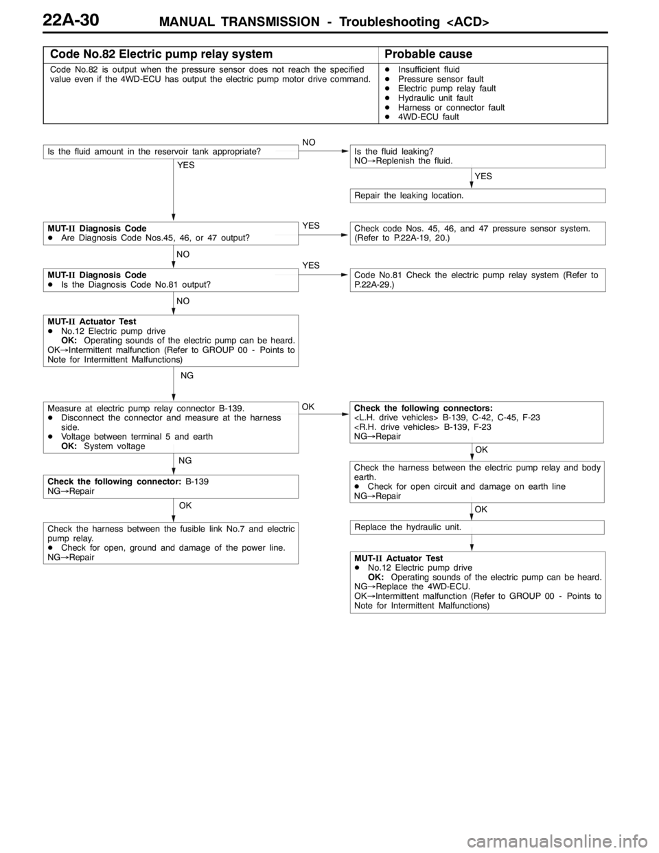
Page 838 of 1449
MANUAL TRANSMISSION - Troubleshooting
Code No.82 Electric pump relay systemProbable cause
Code No.82 is output when the pressure sensor does not reach the specified
value even if the 4WD-ECU has output the electric pump motor drive command.DInsufficient fluid
DPressure sensor fault
DElectric pump relay fault
DHydraulic unit fault
DHarness or connector fault
D4WD-ECU fault
OK
OK
NG
NG
MUT-IIActuator Test
DNo.12 Electric pump drive
OK:Operating sounds of the electric pump can be heard.
OK→Intermittent malfunction (Refer to GROUP 00 - Points to
Note for Intermittent Malfunctions)
Check the following connectors:
NG→Repair
OK
Check the following connector:B-139
NG→Repair
Check the harness between the fusible link No.7 and electric
pump relay.
DCheck for open, ground and damage of the power line.
NG→Repair
Measure at electric pump relay connector B-139.
DDisconnect the connector and measure at the harness
side.
DVoltage between terminal 5 and earth
OK:System voltage
MUT-IIActuator Test
DNo.12 Electric pump drive
OK:Operating sounds of the electric pump can be heard.
NG→Replace the 4WD-ECU.
OK→Intermittent malfunction (Refer to GROUP 00 - Points to
Note for Intermittent Malfunctions)
YES
NOIs the fluid amount in the reservoir tank appropriate?
YES
Is the fluid leaking?
NO→Replenish the fluid.
Repair the leaking location.
YES
NO
MUT-IIDiagnosis Code
DAre Diagnosis Code Nos.45, 46, or 47 output?Check code Nos. 45, 46, and 47 pressure sensor system.
(Refer to P.22A-19, 20.)
YESCode No.81 Check the electric pump relay system (Refer to
P.22A-29.)
NO
MUT-IIDiagnosis Code
DIs the Diagnosis Code No.81 output?
OK
Check the harness between the electric pump relay and body
earth.
DCheck for open circuit and damage on earth line
NG→Repair
Replace the hydraulic unit.
Page 839 of 1449
MANUAL TRANSMISSION - Troubleshooting
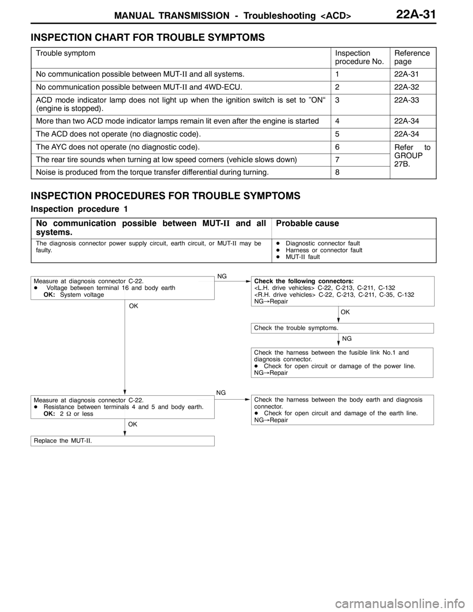
INSPECTION CHART FOR TROUBLE SYMPTOMS
Trouble symptomInspection
procedure No.Reference
page
No communication possible between MUT-IIand all systems.122A-31
No communication possible between MUT-IIand 4WD-ECU.222A-32
ACD mode indicator lamp does not light up when the ignition switch is set to ”ON“
(engine is stopped).322A-33
More than two ACD mode indicator lamps remain lit even after the engine is started422A-34
The ACD does not operate (no diagnostic code).522A-34
The AYC does not operate (no diagnostic code).6Refer to
GROUPThe rear tire sounds when turning at low speed corners (vehicle slows down)7GROUP
27B.
Noise is produced from the torque transfer differential during turning.8
27B.
INSPECTION PROCEDURES FOR TROUBLE SYMPTOMS
Inspection procedure 1
No communication possible between MUT-IIand all
systems.
Probable cause
The diagnosis connector power supply circuit, earth circuit, or MUT-IImay be
faulty.DDiagnostic connector fault
DHarness or connector fault
DMUT-IIfault
OK
NG
NG
Check the harness between the fusible link No.1 and
diagnosis connector.
DCheck for open circuit or damage of the power line.
NG→Repair
OK
Check the trouble symptoms.
Measure at diagnosis connector C-22.
DVoltage between terminal 16 and body earth
OK:System voltageNGCheck the following connectors:
NG→Repair
Check the harness between the body earth and diagnosis
connector.
DCheck for open circuit and damage of the earth line.
NG→Repair
OK
Replace the MUT-II.
Measure at diagnosis connector C-22.
DResistance between terminals 4 and 5 and body earth.
OK:2Ωor less
Page 840 of 1449
MANUAL TRANSMISSION - Troubleshooting
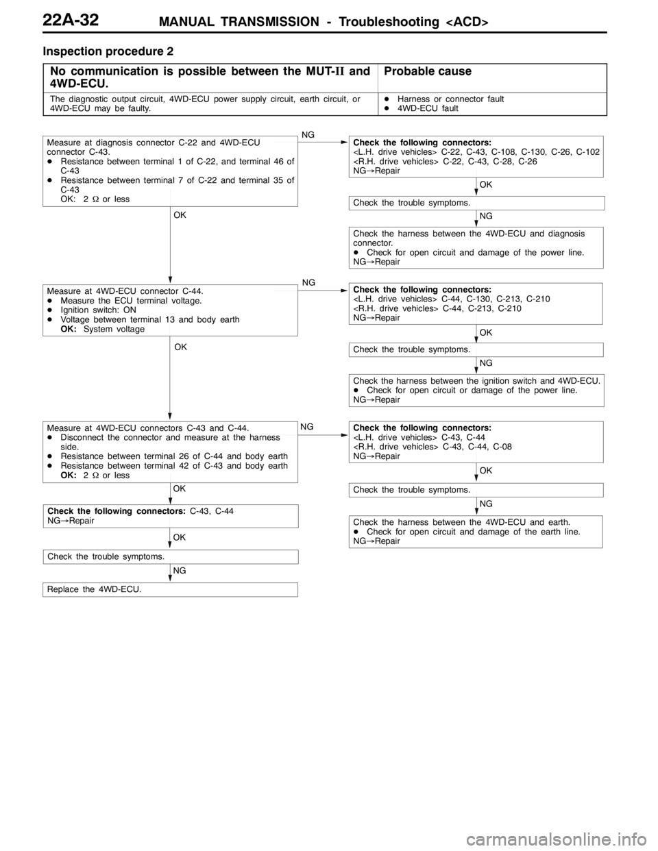
Inspection procedure 2
No communication is possible between the MUT-IIand
4WD-ECU.
Probable cause
The diagnostic output circuit, 4WD-ECU power supply circuit, earth circuit, or
4WD-ECU may be faulty.DHarness or connector fault
D4WD-ECU fault
NG OK OK
NG OK OK
NG OK
OK
NG
NG
NG
Check the trouble symptoms.
Check the harness between the 4WD-ECU and earth.
DCheck for open circuit and damage of the earth line.
NG→Repair
Check the following connectors:
NG→Repair
Check the harness between the ignition switch and 4WD-ECU.
DCheck for open circuit or damage of the power line.
NG→Repair
Check the trouble symptoms.
Measure at 4WD-ECU connector C-44.
DMeasure the ECU terminal voltage.
DIgnition switch: ON
DVoltage between terminal 13 and body earth
OK:System voltageCheck the following connectors:
NG→Repair
Check the harness between the 4WD-ECU and diagnosis
connector.
DCheck for open circuit and damage of the power line.
NG→Repair
Check the trouble symptoms.
Measure at diagnosis connector C-22 and 4WD-ECU
connector C-43.
DResistance between terminal 1 of C-22, and terminal 46 of
C-43
DResistance between terminal 7 of C-22 and terminal 35 of
C-43
OK: 2Ωor lessCheck the following connectors:
NG→Repair
Replace the 4WD-ECU.
Measure at 4WD-ECU connectors C-43 and C-44.
DDisconnect the connector and measure at the harness
side.
DResistance between terminal 26 of C-44 and body earth
DResistance between terminal 42 of C-43 and body earth
OK:2Ωor less
NG OK
Check the trouble symptoms.
Check the following connectors:C-43, C-44
NG→Repair
Page 841 of 1449
MANUAL TRANSMISSION - Troubleshooting
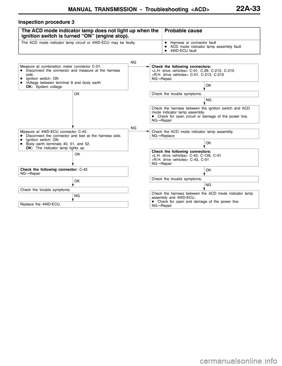
Inspection procedure 3
The ACD mode indicator lamp does not light up when the
ignition switch is turned “ON” (engine stop).
Probable cause
The ACD mode indicator lamp circuit or 4WD-ECU may be faulty.DHarness or connector fault
DACD mode indicator lamp assembly fault
D4WD-ECU fault
OK OK OKOK
NG
OK
NG
NG
NG
Check the harness between the ACD mode indicator lamp
assembly and 4WD-ECU.
DCheck for open and damage of the power line.
NG→Repair
Replace the 4WD-ECU.
Measure at 4WD-ECU connector C-43.
DDisconnect the connector and test at the harness side.
DIgnition switch: ON
DBody earth terminals 40, 51, and 52.
OK:The indicator lamp lights up.
Check the trouble symptoms.
Measure at combination meter connector C-01.
DDisconnect the connector and measure at the harness
side.
DIgnition switch: ON
DVoltage between terminal 9 and body earth
OK:System voltageCheck the following connectors:
NG→Repair
Check the trouble symptoms.
Check the ACD mode indicator lamp assembly.
NG→Replace
Check the harness between the ignition switch and ACD
mode indicator lamp assembly.
DCheck for open circuit or damage of the power line.
NG→Repair
Check the following connectors:
NG→Repair
OK
NG
Check the trouble symptoms.
Check the following connector:C-43
NG→Repair