2007 MITSUBISHI LANCER EVOLUTION ECU
[x] Cancel search: ECUPage 693 of 1449

ENGINE COOLING -Troubleshooting14-5
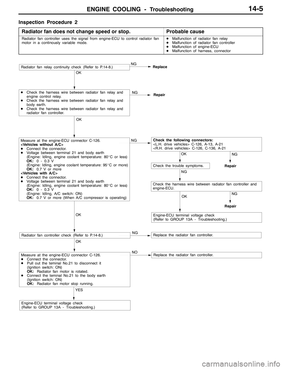
Inspection Procedure 2
Radiator fan does not change speed or stop.
Probable cause
Radiator fan controller uses the signal from engine-ECU to control radiator fan
motor in a continously variable mode.DMalfunction of radiator fan relay
DMalfunction of radiator fan controller
DMalfunction of engine-ECU
DMalfunction of harness, connector
Measure at the engine-ECU connector C-126.
DConnect the connector.
DPull out the teminal No.21 to disconnect it
(Ignition switch: ON)
OK:Radiator fan motor is rotated.
DConnect the teminal No.21 to the body earth
(Ignition switch: ON)
OK:Radiator fan motor stop running.
YES
Engine-ECU terminal voltage check
(Refer to GROUP 13A - Troubleshooting.)NO
Replace the radiator fan controller.
OK
Radiator fan controller check (Refer to P.14-8.)NGReplace the radiator fan controller.
OK
Measure at the engine-ECU connector C-126.
DConnect the connector.
DVoltage between terminal 21 and body earth
(Engine: Idling, engine coolant temperature: 80_C or less)
OK:0 - 0.3 V
(Engine: Idling, engine coolant temperature: 95_C or more)
OK:0.7 V or more
DConnect the connector.
DVoltage between terminal 21 and body earth
(Engine: Idling, engine coolant temperature: 80_C or less)
OK:0 - 0.3 V
(Engine: Idling, A/C switch: ON)
OK:0.7 V or more (When A/C compressor is operating)NG
OK
DCheck the harness wire between radiator fan relay and
engine control relay.
DCheck the harness wire between radiator fan relay and
body earth.
DCheck the harness wire between radiator fan relay and
radiator fan controller.NG
Repair
NG
Replace
OK
OK
OK
Check the following connectors:
NG
Engine-ECU terminal voltage check
(Refer to GROUP 13A - Troubleshooting.)
Check the trouble symptoms.
NG
NG
Repair
Repair
Radiator fan relay continuity check (Refer to P.14-8.)
Check the harness wire between radiator fan controller and
engine-ECU.
Page 695 of 1449

ENGINE COOLING -On-vehicle ServiceENGINE COOLING -On-vehicle Service14-7
3. Remove the cylinder block drain plug from the cylinder
block to drain the engine coolant.
4. Remove the reserve tank to drain the engine coolant.
5. When the engine coolant has drained, pour in water from
the radiator cap to clean the engine coolant line.
6. Coat the thread of the cylinder block drain plug with the
specified sealant and tighten to the specified torque.
Specified sealant:
3M Nut Locking Part No. 4171 or equivalent
7. Securely tighten the radiator drain plug.
8. Install the under cover.
(Refer to GROUP 51 - Front Bumper.)
9. Install the reserve tank.
10. Slowly pour the engine coolant into the mouth of the
radiator until the radiator is full, and pour also into the
reserve tank up to the FULL line.
Recommended anti-freeze:
MITUBISHI GENUINE COOLANT or equivalent
Quantity: 6.0 L
Caution
Do not use alcohol or methanol anti-freeze or any
engine coolants mixed with alcohol or methanol
anti-freeze. The use of an improper anti-freeze can
cause the corrosion of the aluminium components.
11. Install the radiator cap securely.
12. Start the engine and warm the engine until the thermostat
opens. (Touch the radiator hose with your hand to check
that warm water is flowing.)
13. After the thermostat opens, race the engine several times,
and then stop the engine.
14. Cool down the engine, and then pour engine coolant into
the reserve tank until the level reaches the FULL line. If
the level is low, repeat the operation from step 11.
CONCENTRATION MEASUREMENT
Measure the temperature and specific gravity of the engine
coolant to check the antifreeze concentration.
Standard value: 30 - 60 % (allowable concentration range)
RECOMMENDED ANTI-FREEZE
AntifreezeAllowable concentration
MITSUBISHI GENUINE COOLANT
or equivalent30 - 60 %
Caution
If the concentration of the anti-freeze is below 30 %, the
anti-corrosion property will be adversely affected. In
addition, if the concentration is above 60 %, both the
anti-freezing and engine cooling properties will decrease,
affecting the engine adversely. For these reasons, be
sure to maintain the concentration level within the
specified range.
44±5N·m
Water inlet
pipe
Page 712 of 1449

INTAKE AND EXHAUST -On-vehicle Service15-6
INTAKE MANIFOLD PRESSURE CHECK
Refer to GROUP 11A – On-vehicle Service.
SECONDARY AIR CONTROL SYSTEM CHECK
1. Start the engine and carry out idling.
2. Confirm that the secondary air valve lifts up when the
engine-ECU connector No. 53 terminal is short-circuited
with the earth using a jumper wire.
The engine-ECU connector must be connected at this
time.
SECONDARY AIR CONTROL SOLENOID
VALVE CHECK
OPERATION CHECK
1. Disconnect the vacuum hose (white-striped, yellow-
striped) from the solenoid valve.
2. Separate the harness connector.
3. Connect the hand vacuum pump to the solenoid valve’s
A nipple.
4. Connect the solenoid valve terminal and battery terminal
with a jumper wire.
5. Disconnect the jumper wire between the battery’s ( - )
terminals, apply a negative pressure, and inspect the
tightness.
Jumper wireState of B
nippleNormal state
ConnectedOpenedNegative pressure leaks.
ClosedNegative pressure is
maintained.
DisconnectedClosedNegative pressure leaks.
Vacuum tank
Secondary
air control
solenoid
valve
Battery A B
Page 714 of 1449

INTAKE AND EXHAUST -Air Cleaner15-8
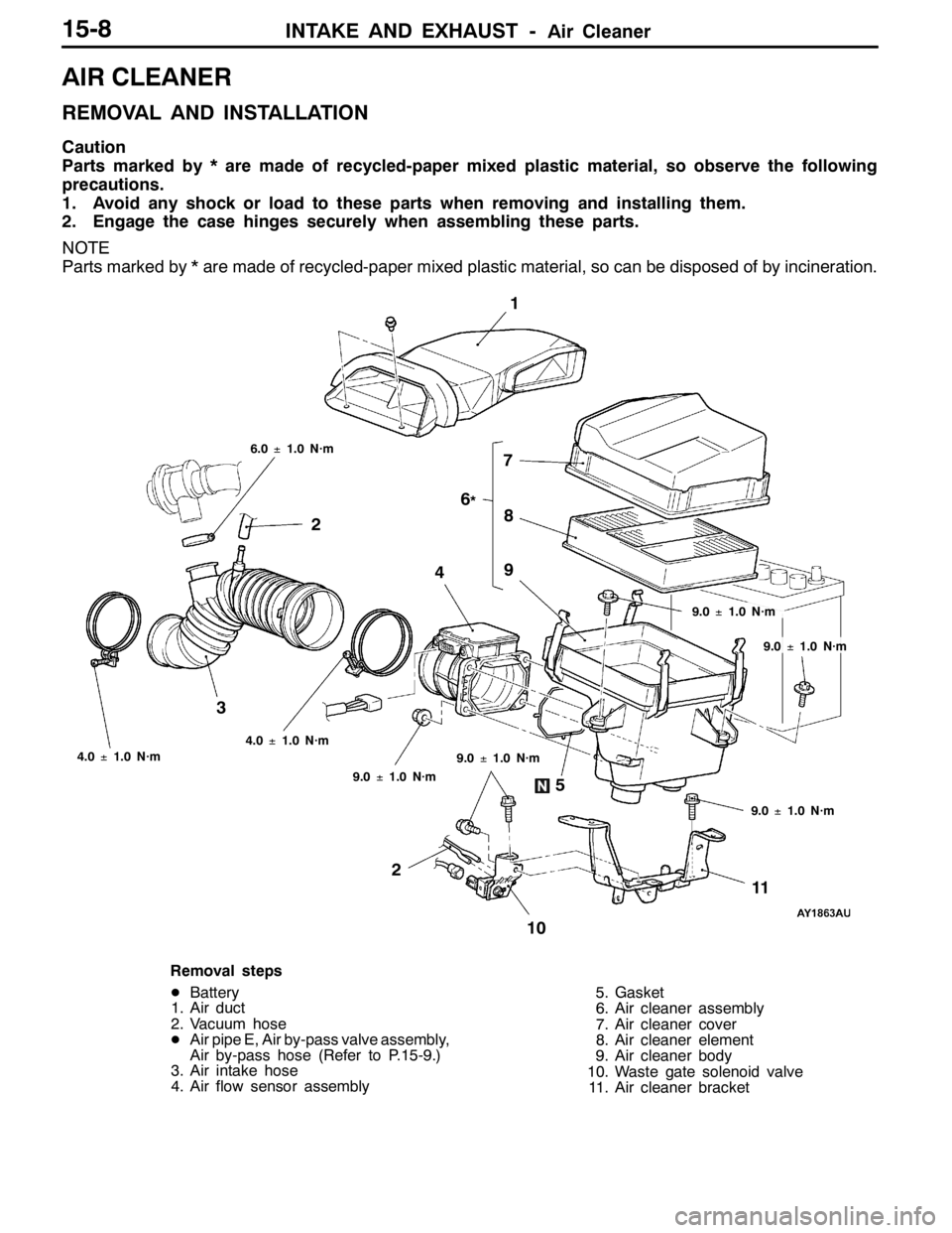
AIR CLEANER
REMOVAL AND INSTALLATION
Caution
Parts marked by * are made of recycled-paper mixed plastic material, so observe the following
precautions.
1. Avoid any shock or load to these parts when removing and installing them.
2. Engage the case hinges securely when assembling these parts.
NOTE
Parts marked by * are made of recycled-paper mixed plastic material, so can be disposed of by incineration.
1
6
*
37
28
5 4
9.0±1.0 N·m 6.0±1.0 N·m
9.0±1.0 N·m
9.0±1.0 N·m 4.0±1.0 N·m
4.0±1.0 N·m
9.0±1.0 N·m
2
9
1011
9.0±1.0 N·m
Removal steps
DBattery
1. Air duct
2. Vacuum hose
DAir pipe E, Air by-pass valve assembly,
Air by-pass hose (Refer to P.15-9.)
3. Air intake hose
4. Air flow sensor assembly5. Gasket
6. Air cleaner assembly
7. Air cleaner cover
8. Air cleaner element
9. Air cleaner body
10. Waste gate solenoid valve
11. Air cleaner bracket
Page 734 of 1449

ENGINE ELECTRICAL -Charging System16-2
CHARGING SYSTEM
GENERAL INFORMATION
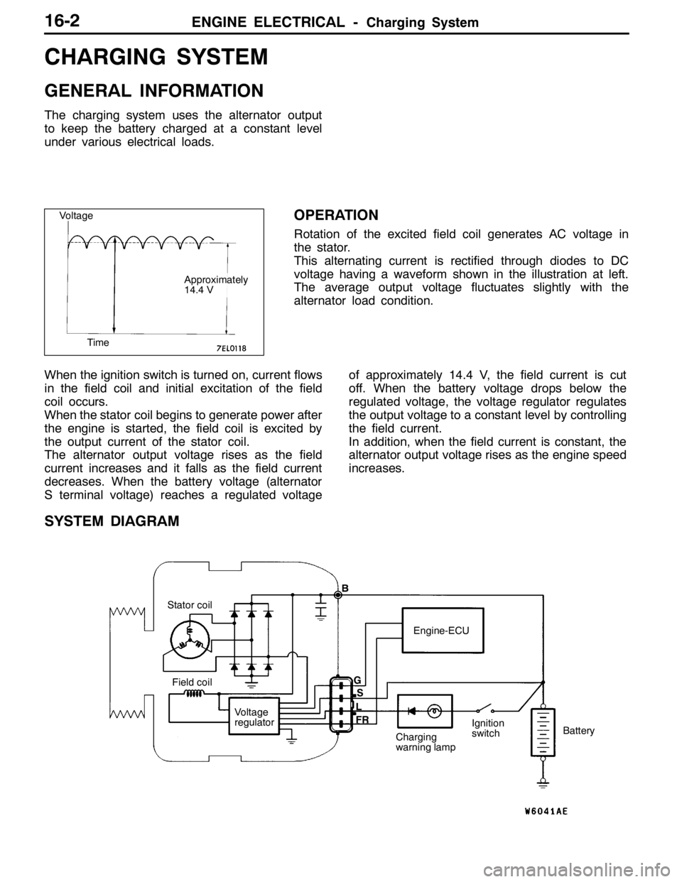
The charging system uses the alternator output
to keep the battery charged at a constant level
under various electrical loads.
OPERATION
Rotation of the excited field coil generates AC voltage in
the stator.
This alternating current is rectified through diodes to DC
voltage having a waveform shown in the illustration at left.
The average output voltage fluctuates slightly with the
alternator load condition.
When the ignition switch is turned on, current flows
in the field coil and initial excitation of the field
coil occurs.
When the stator coil begins to generate power after
the engine is started, the field coil is excited by
the output current of the stator coil.
The alternator output voltage rises as the field
current increases and it falls as the field current
decreases. When the battery voltage (alternator
S terminal voltage) reaches a regulated voltageof approximately 14.4 V, the field current is cut
off. When the battery voltage drops below the
regulated voltage, the voltage regulator regulates
the output voltage to a constant level by controlling
the field current.
In addition, when the field current is constant, the
alternator output voltage rises as the engine speed
increases.
SYSTEM DIAGRAM
Stator coil
Field coil
Voltage
regulatorEngine-ECU
Charging
warning lampIgnition
switchBattery B
G
L
FRS
Voltage
Time
Approximately
14.4 V
Page 737 of 1449

ENGINE ELECTRICAL -Charging System16-5
(6) Reconnect the negative battery cable.
(7) Connect a tachometer or the MUT-II.
(Refer to GROUP 11 - On-vehicle Service.)
(8) Leave the hood open.
(9) Start the engine.
(10)With the engine running at 2,500 r/min, turn
the headlamps and other lamps on and off
to adjust the alternator load so that the value
displayed on the ammeter is slightly above 30
A.
Adjust the engine speed by gradually
decreasing it until the value displayed on the
ammeter is 30 A. Take a reading of the value
displayed on the voltmeter at this time.
Limit: max. 0.3 V
NOTE
When the alternator output is high and the value
displayed on the ammeter does not decrease
until 30 A, set the value to 40 A. Read the
value displayed on the voltmeter at this time.
When the value range is 40 A, the limit is max.
0.4 V.(11) If the value displayed on the voltmeter is above
the limit value, there is probably a malfunction
in the alternator output wire, so check the wiring
between the alternator “B” terminal and the
battery (+) terminal (including fusible link).
If a terminal is not sufficiently tight or if the
harness has become discolored due to
overheating, repair and then test again.
(12)After the test, run the engine at idle.
(13)Turn off all lamps and the ignition switch.
(14)Remove the tachometer or the MUT-II.
(15)Disconnect the negative battery cable.
(16)Disconnect the ammeter and voltmeter.
(17)Connect the alternator output wire to the
alternator “B” terminal.
(18)Connect the negative battery cable.
OUTPUT CURRENT TEST
Charging warning lampVoltmeter
Ammeter
Ignition switch
Alternator relayLoad
Battery
Engine-ECUAlternatorFR
L
S
G
+ -+-
B
Page 739 of 1449

ENGINE ELECTRICAL -Charging System16-7
REGULATED VOLTAGE TEST
B
BlueRed
Ignition
switchLoad
FR
L
S
GMB991519
Alternator
BatteryVoltmeterAmmeter
Yellow
Engine-ECU
Black
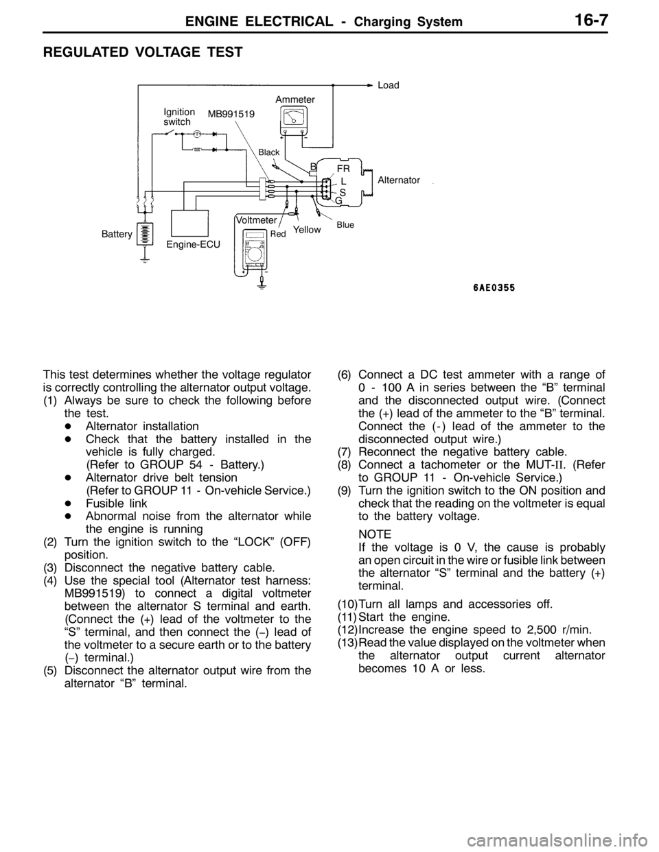
This test determines whether the voltage regulator
is correctly controlling the alternator output voltage.
(1) Always be sure to check the following before
the test.
DAlternator installation
DCheck that the battery installed in the
vehicle is fully charged.
(Refer to GROUP 54 - Battery.)
DAlternator drive belt tension
(Refer to GROUP 11 - On-vehicle Service.)
DFusible link
DAbnormal noise from the alternator while
the engine is running
(2) Turn the ignition switch to the “LOCK” (OFF)
position.
(3) Disconnect the negative battery cable.
(4) Use the special tool (Alternator test harness:
MB991519) to connect a digital voltmeter
between the alternator S terminal and earth.
(Connect the (+) lead of the voltmeter to the
“S” terminal, and then connect the (−) lead of
the voltmeter to a secure earth or to the battery
(−) terminal.)
(5) Disconnect the alternator output wire from the
alternator “B” terminal.(6) Connect a DC test ammeter with a range of
0 - 100 A in series between the “B” terminal
and the disconnected output wire. (Connect
the (+) lead of the ammeter to the “B” terminal.
Connect the ( - ) lead of the ammeter to the
disconnected output wire.)
(7) Reconnect the negative battery cable.
(8) Connect a tachometer or the MUT-II. (Refer
to GROUP 11 - On-vehicle Service.)
(9) Turn the ignition switch to the ON position and
check that the reading on the voltmeter is equal
to the battery voltage.
NOTE
If the voltage is 0 V, the cause is probably
an open circuit in the wire or fusible link between
the alternator “S” terminal and the battery (+)
terminal.
(10)Turn all lamps and accessories off.
(11) Start the engine.
(12)Increase the engine speed to 2,500 r/min.
(13)Read the value displayed on the voltmeter when
the alternator output current alternator
becomes 10 A or less.
Page 758 of 1449

ENGINE ELECTRICAL -Ignition System16-26
IGNITION SYSTEM
GENERAL INFORMATION
This system is equipped with two ignition coils (A
and B) with built-in power transistors for the No.
1 and No. 4 cylinders and the No. 2 and No. 3
cylinders respectively.
Interruption of the primary current flowing in the
primary side of ignition coil A generates a high
voltage in the secondary side of ignition coil A.
The high voltage thus generated is applied to the
spark plugs of No. 1 and No. 4 cylinders to generate
sparks. At the time that the sparks are generated
at both spark plugs, if one cylinder is at the
compression stroke, the other cylinder is at the
exhaust stroke, so that ignition of the compressed
air/fuel mixture occurs only for the cylinder which
is at the compression stroke.
In the same way, when the primary current flowing
in ignition coil B is interrupted, the high voltage
thus generated is applied to the spark plugs of
No. 2 and No. 3 cylinders.
The Engine-ECU turns the two power transistors
inside the ignition coils alternately on and off. Thiscauses the primary currents in the ignition coils
to be alternately interrupted and allowed to flow
to fire the cylinders in the order 1-3-4-2.
The Engine-ECU determines which ignition coil
should be controlled by means of the signals from
the camshaft position sensor which is incorporated
in the camshaft and from the crank angle sensor
which is incorporated in the crankshaft. It also
detects the crankshaft position in order to provide
ignition at the most appropriate timing in response
to the engine operation conditions. It also detects
the crankshaft position in order to provide ignition
at the most appropriate timing in response to the
engine operation conditions.
When the engine is cold or operated at high
altitudes, the ignition timing is slightly advanced
to provide optimum performance.
When the automatic transmission shifts gears, the
ignition timing is also retarded in order to reduce
output torque, thereby alleviating shifting shocks.
SYSTEM DIAGRAM
Barometric pressure sensor
Intake air temperature sensor
Engine coolant temperature sensor
Camshaft position sensor
Crank angle sensor
Ignition switch - ST
Vehicle speed signalEngine-ECU
Ignition coil A
Ignition coil B Ignition switch
Spark plugBattery
To tachometerCylinder No. Air flow sensor
1 4
23
Detonation sensor