Page 670 of 1449

MPI -On-vehicle Service13A-138
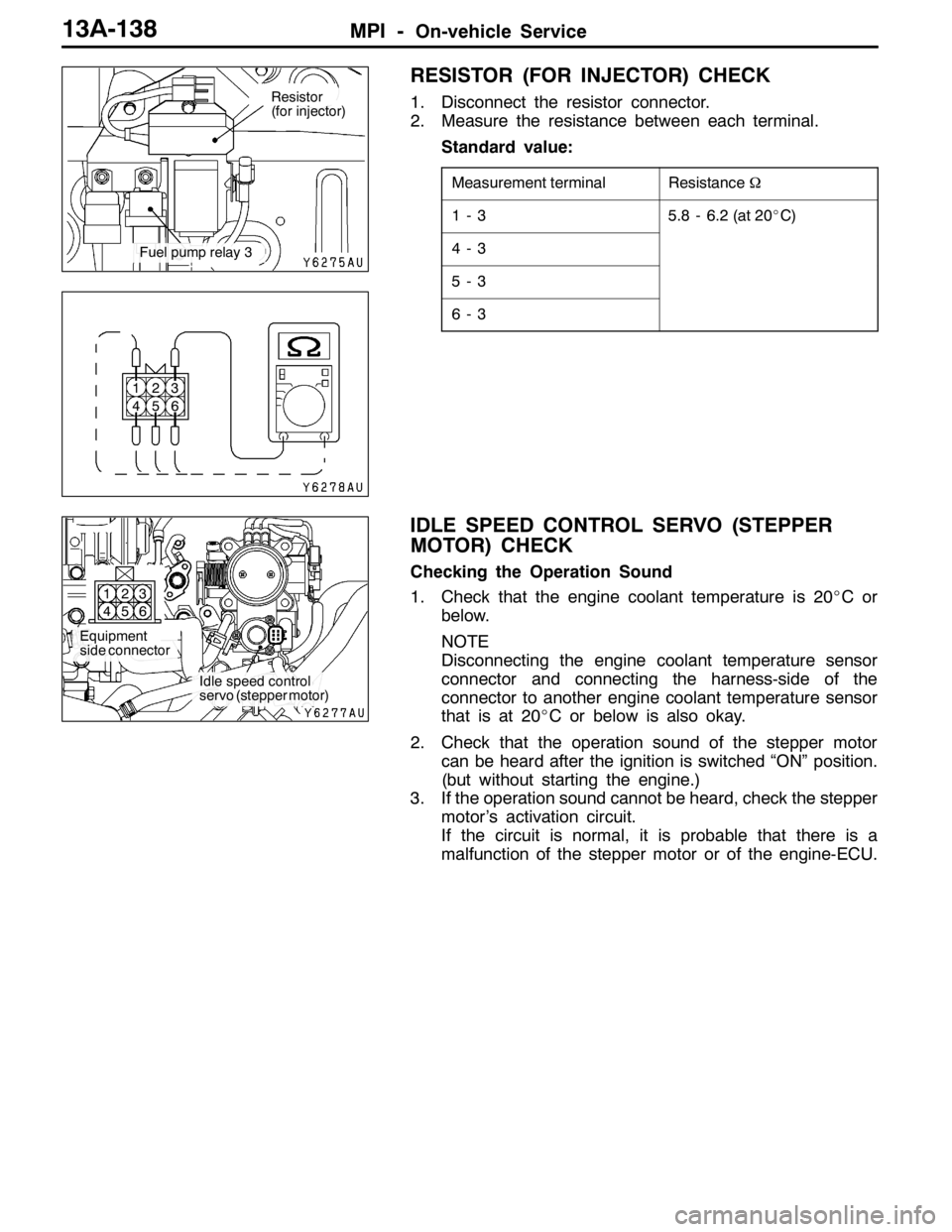
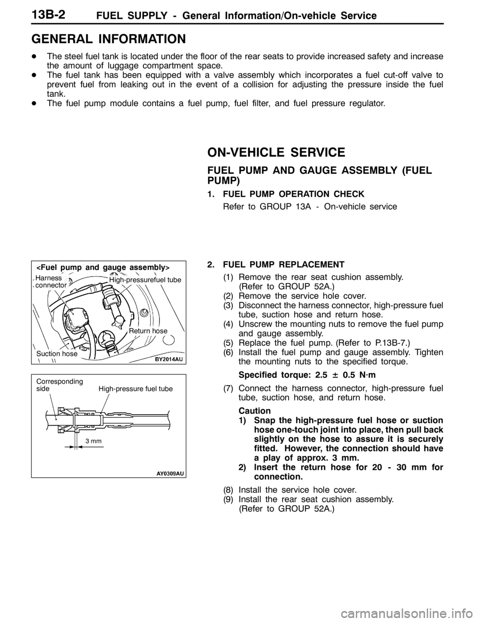
RESISTOR (FOR INJECTOR) CHECK
1. Disconnect the resistor connector.
2. Measure the resistance between each terminal.
Standard value:
Measurement terminalResistanceΩ
1-35.8 - 6.2 (at 20_C)
4-3
5-3
6-3
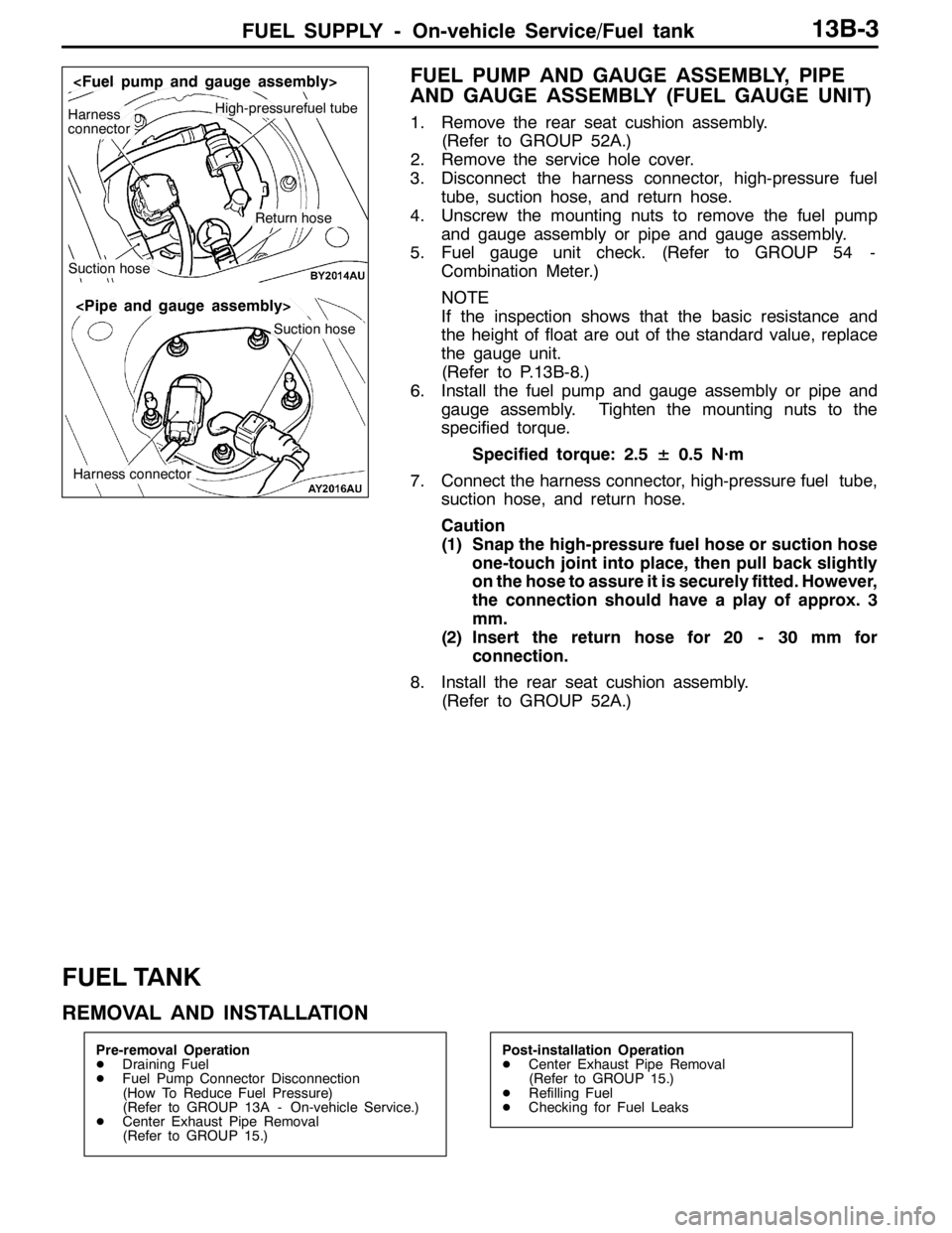
IDLE SPEED CONTROL SERVO (STEPPER
MOTOR) CHECK
Checking the Operation Sound
1. Check that the engine coolant temperature is 20_Cor
below.
NOTE
Disconnecting the engine coolant temperature sensor
connector and connecting the harness-side of the
connector to another engine coolant temperature sensor
that is at 20_C or below is also okay.
2. Check that the operation sound of the stepper motor
can be heard after the ignition is switched “ON” position.
(but without starting the engine.)
3. If the operation sound cannot be heard, check the stepper
motor’s activation circuit.
If the circuit is normal, it is probable that there is a
malfunction of the stepper motor or of the engine-ECU.
Resistor
(for injector)
Fuel pump relay 3
1
42
53
6
Equipment
side connector
Idle speed control
servo (stepper motor) 1
42
53
6
Page 679 of 1449
MPI -Engine-ECU13A-147
ENGINE-ECU
REMOVAL AND INSTALLATION
Pre-removal and Post-installation Operations
Glove Box Assembly Removal and Installation (Refer
to GROUP 52A - Instrument Panel.)
15.0±1.0N·m
2
Removal steps
1. Engine-ECU connector
2. Engine-ECU
Page 682 of 1449

FUEL SUPPLY - General Information/On-vehicle Service13B-2
GENERAL INFORMATION
DThe steel fuel tank is located under the floor of the rear seats to provide increased safety and increase
the amount of luggage compartment space.
DThe fuel tank has been equipped with a valve assembly which incorporates a fuel cut-off valve to
prevent fuel from leaking out in the event of a collision for adjusting the pressure inside the fuel
tank.
DThe fuel pump module contains a fuel pump, fuel filter, and fuel pressure regulator.
ON-VEHICLE SERVICE
FUEL PUMP AND GAUGE ASSEMBLY (FUEL
PUMP)
1. FUEL PUMP OPERATION CHECK
Refer to GROUP 13A - On-vehicle service
2. FUEL PUMP REPLACEMENT
(1) Remove the rear seat cushion assembly.
(Refer to GROUP 52A.)
(2) Remove the service hole cover.
(3) Disconnect the harness connector, high-pressure fuel
tube, suction hose and return hose.
(4) Unscrew the mounting nuts to remove the fuel pump
and gauge assembly.
(5) Replace the fuel pump. (Refer to P.13B-7.)
(6) Install the fuel pump and gauge assembly. Tighten
the mounting nuts to the specified torque.
Specified torque: 2.5± 0.5 N·m
(7) Connect the harness connector, high-pressure fuel
tube, suction hose, and return hose.
Caution
1) Snap the high-pressure fuel hose or suction
hose one-touch joint into place, then pull back
slightly on the hose to assure it is securely
fitted. However, the connection should have
a play of approx. 3 mm.
2) Insert the return hose for 20 - 30 mm for
connection.
(8) Install the service hole cover.
(9) Install the rear seat cushion assembly.
(Refer to GROUP 52A.)
Harness
connectorHigh-pressurefuel tube
Suction hose
Return hose
3mm
Corresponding
sideHigh-pressure fuel tube
Page 683 of 1449

FUEL SUPPLY - On-vehicle Service/Fuel tank13B-3
FUEL PUMP AND GAUGE ASSEMBLY, PIPE
AND GAUGE ASSEMBLY (FUEL GAUGE UNIT)
1. Remove the rear seat cushion assembly.
(Refer to GROUP 52A.)
2. Remove the service hole cover.
3. Disconnect the harness connector, high-pressure fuel
tube, suction hose, and return hose.
4. Unscrew the mounting nuts to remove the fuel pump
and gauge assembly or pipe and gauge assembly.
5. Fuel gauge unit check. (Refer to GROUP 54 -
Combination Meter.)
NOTE
If the inspection shows that the basic resistance and
the height of float are out of the standard value, replace
the gauge unit.
(Refer to P.13B-8.)
6. Install the fuel pump and gauge assembly or pipe and
gauge assembly. Tighten the mounting nuts to the
specified torque.
Specified torque: 2.5± 0.5 N·m
7. Connect the harness connector, high-pressure fuel tube,
suction hose, and return hose.
Caution
(1) Snap the high-pressure fuel hose or suction hose
one-touch joint into place, then pull back slightly
on the hose to assure it is securely fitted. However,
the connection should have a play of approx. 3
mm.
(2) Insert the return hose for 20 - 30 mm for
connection.
8. Install the rear seat cushion assembly.
(Refer to GROUP 52A.)
FUEL TANK
REMOVAL AND INSTALLATION
Pre-removal Operation
DDraining Fuel
DFuel Pump Connector Disconnection
(How To Reduce Fuel Pressure)
(Refer to GROUP 13A - On-vehicle Service.)
DCenter Exhaust Pipe Removal
(Refer to GROUP 15.)Post-installation Operation
DCenter Exhaust Pipe Removal
(Refer to GROUP 15.)
DRefilling Fuel
DChecking for Fuel Leaks
High-pressurefuel tubeHarness
connector
Suction hose
Return hose
Suction hose
Harness connector
Page 686 of 1449
FUEL SUPPLY - Fuel Tank13B-6
INSTALLATION SERVICE POINT
"AAHIGH-PRESSURE FUEL HOSE/SUCTION HOSE
INSTALLATION
Caution
Snap the high-pressure fuel hose or suction hose
one-touch joint into place, then pull back slightly on the
hose to assure it is securely fitted. However, the
connection should have a play of approx. 3 mm.
"BAFUEL TANK RETURN HOSE INSTALLATION
Caution
Insert the return hose for 20 - 30 mm for connection.
3mm
Corresponding
sideHigh-pressure fuel tube
Page 690 of 1449

ENGINE COOLING -GeneralInformation/
Service Specifications/Lubricant/Sealant14-2
GENERAL INFORMATION
The cooling system is designed to keep every part
of the engine at appropriate temperature in
whatever condition the engine may be operated.
The cooling method is of the water-cooled, pressure
forced circulation type in which the water pump
pressurizes coolant and circulates it throughout the
engine. If the coolant temperature exceeds the
prescribed temperature, the thermostat opens to
circulate the coolant through the radiator as well
so that the heat absorbed by the coolant may be
radiated into the air.The water pump is of the centrifugal type and is
driven by the drive belt from the crankshaft.
The radiator is the corrugated fin, down flow type.
The cooling fan is controlled by the radiator fan
controller and engine-ECU depend on driving
conditions.
ItemSpecification
Radiator performance kJ/h216,700
SERVICE SPECIFICATIONS
ItemsStandard valueLimit
Radiator cap opening pressure kPa93 - 12383
Range of coolant antifreeze concentration of radiator %30 - 60-
ThermostatValve opening temperature of thermostat_C80±1.5-
Full-opening temperature of thermostat_C93-
Valve lift (at 93_C) mm9.5 or more-
LUBRICANT
ItemSpecified coolantQuantity L
Engine coolantMITSUBISHI GENUINE COOLANT or equivalent6.0Enginecoolant
(including reserve tank)
MITSUBISHIGENUINECOOLANTorequivalent6.0
SEALANT
ItemSpecified sealantRemark
Cylinder block drain plug3M Nut Locking Part No. 4171 or equivalentDrying sealant
Page 691 of 1449

ENGINE COOLING -Special Tools/Troubleshooting14-3
SPECIAL TOOLS
ToolNumberNameUse
A
B
C
DMB991223
A: MB991219
B: MB991220
C: MB991221
D: MB991222Harness set
A: Test harness
B: LED harness
C: LED harness
adapter
D: ProbeDMeasurement of terminal voltage
DInspection of radiator fan controller
A: Connector pin contact pressure
inspection
B: Power circuit inspection
C: Power circuit inspection
D: Commercial tester connection
MB991658Test harnessInspection of radiator fan controller
APS
MB991791Throttle cotrollerInspection of radiator fan controller
[Use the accelerator pedal position sensor
disconnected from harness.]
TROUBLESHOOTING
INSPECTION CHART FOR TROUBLE SYMPTOMS
Trouble symptomsInspection procedure
No.Reference page
Radiator fan does not operate.114-3
Radiator fan does not change speed or stop.214-5
INSPECTION PROCEDURE FOR TROUBLE SYMPTOMS
Inspection Procedure 1
Radiator fan does not operate.
Probable cause
Failure may occur on the power supply of the radiator fan controller and the
earth circuit.
Failure may also occur on the radiator fan controller and engine-ECU.DMalfunction of fusible link
DMalfunction of radiator fan relay
DMalfunction of radiator fan controller
DMalfunction of radiator fan motor
DMalfunction of engine-ECU
DMalfunction of harness, connector
Page 692 of 1449

ENGINE COOLING -Troubleshooting14-4
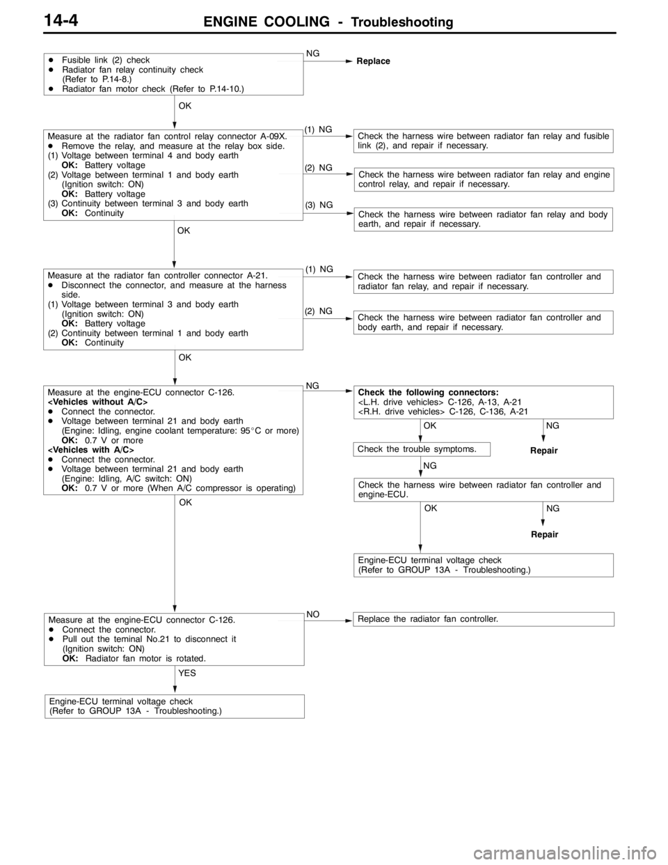
Measure at the engine-ECU connector C-126.
DConnect the connector.
DPull out the teminal No.21 to disconnect it
(Ignition switch: ON)
OK:Radiator fan motor is rotated.
YES
Engine-ECU terminal voltage check
(Refer to GROUP 13A - Troubleshooting.)NO
Replace the radiator fan controller.
NG
Repair
OK
NG
Repair
OK
Check the harness wire between radiator fan controller and
engine-ECU.
Measure at the engine-ECU connector C-126.
DConnect the connector.
DVoltage between terminal 21 and body earth
(Engine: Idling, engine coolant temperature: 95_C or more)
OK:0.7 V or more
DConnect the connector.
DVoltage between terminal 21 and body earth
(Engine: Idling, A/C switch: ON)
OK:0.7 V or more (When A/C compressor is operating)NG
(2) NGCheck the harness wire between radiator fan controller and
body earth, and repair if necessary.
OK
Measure at the radiator fan controller connector A-21.
DDisconnect the connector, and measure at the harness
side.
(1) Voltage between terminal 3 and body earth
(Ignition switch: ON)
OK:Battery voltage
(2) Continuity between terminal 1 and body earth
OK:Continuity(1) NGCheck the harness wire between radiator fan controller and
radiator fan relay, and repair if necessary.
(3) NGCheck the harness wire between radiator fan relay and body
earth, and repair if necessary.
(2) NGCheck the harness wire between radiator fan relay and engine
control relay, and repair if necessary.
OK
Measure at the radiator fan control relay connector A-09X.
DRemove the relay, and measure at the relay box side.
(1) Voltage between terminal 4 and body earth
OK:Battery voltage
(2) Voltage between terminal 1 and body earth
(Ignition switch: ON)
OK:Battery voltage
(3) Continuity between terminal 3 and body earth
OK:Continuity(1) NGCheck the harness wire between radiator fan relay and fusible
link (2), and repair if necessary.
DFusible link (2) check
DRadiator fan relay continuity check
(Refer to P.14-8.)
DRadiator fan motor check (Refer to P.14-10.)NG
Replace
OK
OK
Engine-ECU terminal voltage check
(Refer to GROUP 13A - Troubleshooting.)
Check the following connectors:
C-126, A-13, A-21
C-126, C-136, A-21
NG
Check the trouble symptoms.