2007 MITSUBISHI LANCER EVOLUTION steering
[x] Cancel search: steeringPage 1302 of 1449

SRS - Air Bag Modules and Clock Spring52B-58
"CASTEERING WHEEL/STEERING WHEEL - AIR BAG
MODULE ASSEMBLY INSTALLATION
1. After checking that centering of the clock spring has been
done, install the steering wheel or the steering wheel - air
bag module assembly.
Caution
Do not engage the harness of the clock spring when
installing the steering wheel or the steering wheel - air
bag module assembly.
2. After installation, check that no abnormalities occur when
the steering wheel is fully turned to the left or the right.
"DAPOST-INSTALLATION INSPECTION
1. Check that no abnormal noise or improper operation can
be caused by rotating the steering wheel in left and right
directions slightly.
(driver’s air bag module, clock spring)
2. Turn the ignition switch to the ON position.
3. Check that the SRS warning lamp illuminates for 6 to
8 seconds and goes out.
4. Carry out troubleshooting if the lamp does not go out.
(Refer to P.52-6.)
SRS warning lamp
Page 1303 of 1449

SRS - Air Bag Modules and Clock Spring52B-59
INSPECTION
DRIVER’S AND PASSENGER’S AIR BAG MODULE
INSPECTION
If any malfunction is found in the following inspection, replace
the air bag module(s) with new one(s).
Discard the old one(s) after deployment as specified in the
service procedure. (Refer to P.52B-64.)
Caution
Never measure circuit resistance in the air bag modules
(squib) even with the specified tester. Measuring the
circuit resistance with a tester causes accidental air bag
deployment due to current that flows or static, resulting in
serious personal injury.
1. Check the cover for dents, cracks or deformation.
2. Check the connectors for damage, terminals for
deformation, and harness for binds.
3. Check the air bag inflator cases for dents, cracks or
deformation.
4. With air bag module installed
Caution
If dents, cracks, deformation, or rust are present in
the air bag module(s), replace with new one(s).
Discard the old one(s) as specified in the service
procedure. (Refer to P.52B-64.)
CLOCK SPRING CHECK
If any malfunction is found in the following inspections, replace
the clock spring with a new one.
1. Check the connectors and protective tubes for damage,
and terminals for deformation.
2. Visually check the case for damage.
3. Refer to that the clock spring has continuity between
connector No.2 and terminal No.4 of connector No.1.Inflator
Connector
Connector
Steering
wheel - driver’s
air bag module
assembly
Connector Inflator case
Protective tubes Case
1
2
Page 1309 of 1449

SRS -AirBagModuleandSeatBeltPre-tensioner
Disposal Procedures52B-65
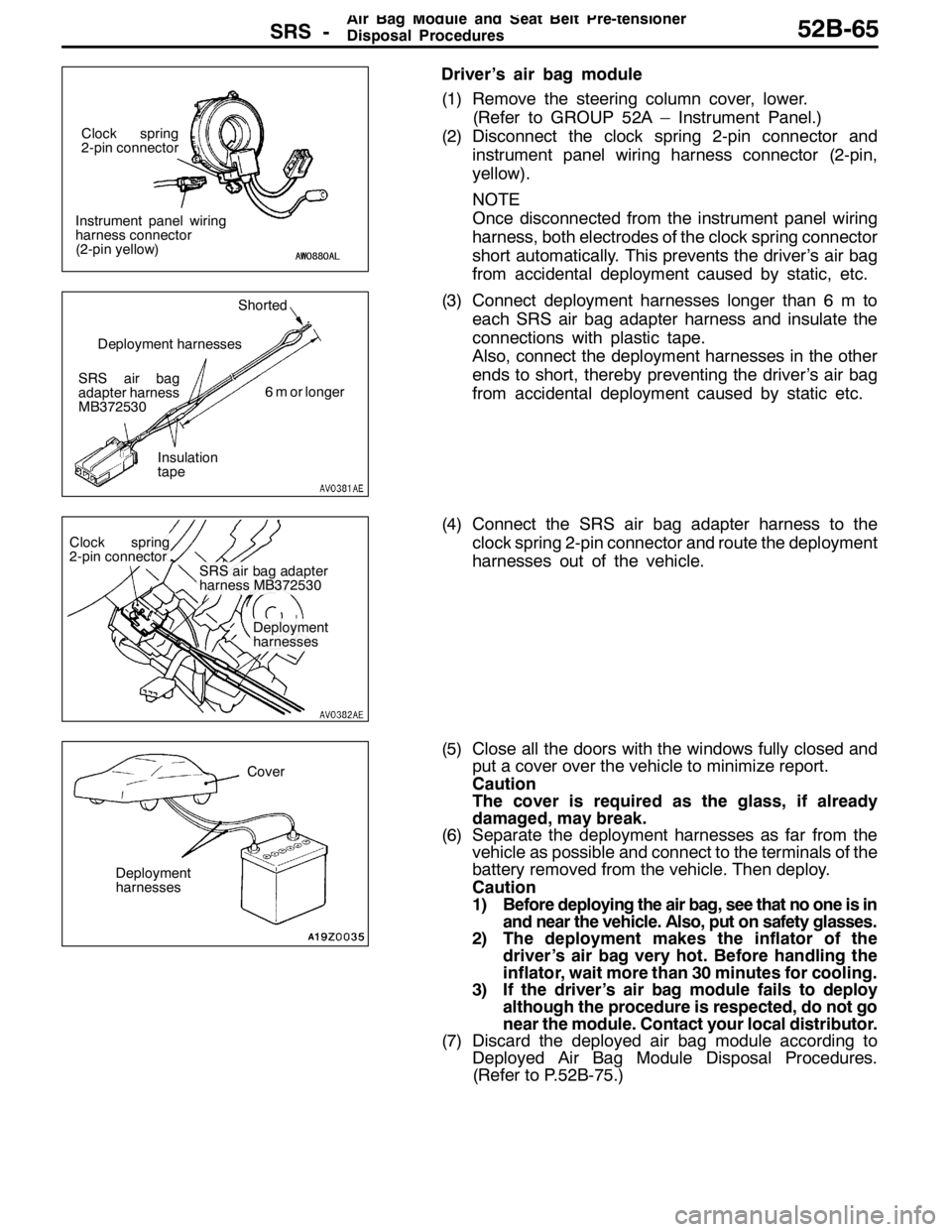
Driver’s air bag module
(1) Remove the steering column cover, lower.
(Refer to GROUP 52A – Instrument Panel.)
(2) Disconnect the clock spring 2-pin connector and
instrument panel wiring harness connector (2-pin,
yellow).
NOTE
Once disconnected from the instrument panel wiring
harness, both electrodes of the clock spring connector
short automatically. This prevents the driver’s air bag
from accidental deployment caused by static, etc.
(3) Connect deployment harnesses longer than 6 m to
each SRS air bag adapter harness and insulate the
connections with plastic tape.
Also, connect the deployment harnesses in the other
ends to short, thereby preventing the driver’s air bag
from accidental deployment caused by static etc.
(4) Connect the SRS air bag adapter harness to the
clock spring 2-pin connector and route the deployment
harnesses out of the vehicle.
(5) Close all the doors with the windows fully closed and
put a cover over the vehicle to minimize report.
Caution
The cover is required as the glass, if already
damaged, may break.
(6) Separate the deployment harnesses as far from the
vehicle as possible and connect to the terminals of the
battery removed from the vehicle. Then deploy.
Caution
1) Before deploying the air bag, see that no one is in
and near the vehicle. Also, put on safety glasses.
2) The deployment makes the inflator of the
driver’s air bag very hot. Before handling the
inflator, wait more than 30 minutes for cooling.
3) If the driver’s air bag module fails to deploy
although the procedure is respected, do not go
near the module. Contact your local distributor.
(7) Discard the deployed air bag module according to
Deployed Air Bag Module Disposal Procedures.
(Refer to P.52B-75.)
Instrument panel wiring
harness connector
(2-pin yellow)Clock spring
2-pin connector
SRS air bag
adapter harness
MB372530Shorted
6 m or longer
Insulation
tape Deployment harnesses
Clock spring
2-pin connector
SRS air bag adapter
harness MB372530
Deployment
harnesses
Cover
Deployment
harnesses
Page 1312 of 1449

SRS -AirBagModuleandSeatBeltPre-tensioner
Disposal Procedures52B-68
(5) Close all the doors with the windows fully closed and
put a cover over the vehicle to minimize report.
Caution
The cover is required as the glass, if already
damaged, may break.
(6) Separate the deployment harnesses as far from the
vehicle as possible and connect to the terminals of
the battery removed from the vehicle. Then deploy.
Caution
1) Before operating the seat belt pre-tensioner,
see that no one is in or near the vehicle.
2) The operation makes the insulator of the seat
belt pre-tensioner very hot. Before handling
the inflator, wait more than 30 minutes for
cooling.
3) If the seat belt pre-tensioner fails to operate
although the procedure is respected, do not go
near the seat belt pre-tensioner. Contact your
local distributor.
(7) Discard the operated seat belt pre-tensioner accord-
ing to Disposal Procedure. (Refer to P.52B-75.)
DEPLOYMENT OUTSIDE THE VEHICLE
Caution
1. Carry out air bag deployment or seat belt pre-tensioner
operation on large flat place at least 6 m away from any
object or person.
2. Avoid a strong wind weather when carrying out
deployment or operation outside the vehicle. Ignite the
air bag at a place upwind from the air bag module and
the seat belt pre-tensioner even in a breeze weather.
1. Disconnect the negative ( - ) and positive (+) battery cables
from the battery terminals, and then remove the battery
from the vehicle.
Caution
Wait at least 60 seconds before any further job after the
disconnection of the battery cables. (Refer to P.52B-3.)
2. Carry out deployment of the air bag module and operation
of the seat belt pre-tensioner according to the following
procedure.
Driver’s side air bag module
(1) Remove the driver’s air bag module from the vehicle.
(Refer to P.52B-52.)
Caution
Once disconnected, both electrodes of the driver’s air
bag module connector short automatically to prevent
accidental deployment caused by static etc. Still, in
consideration of the accidental deployment, store the
air bag module on flat place with deployment surface
facing up. Also, do not put anything on it.
Cover
Deployment
harnesses
Page 1314 of 1449

SRS -AirBagModuleandSeatBeltPre-tensioner
Disposal Procedures52B-70
(7) Separate the deployment harnesses as far from the
driver’s side air bag module as possible and connect
to the terminals of the battery removed from the
vehicle. Then deploy.
Caution
1) Before the deployment, see that no one is near
around the driver’s air bag module.
2) The deployment makes the inflator of the
driver’s air bag very hot. Before handling the
inflator, wait more than 30 minutes for cooling.
3) If the driver’s air bag module fails to deploy
although the procedure is respected, do not go
near the module. Contact your local
distributor.
(8) Discard the deployed air bag module as specified
in Deployed Air Bag Module Disposal Procedures.
(Refer to P.52B-75.)
Driver’s side air bag module
(1) Remove the steering wheel - air bag module assembly
from the vehicle. (Refer to P.52B-52.)
Caution
Once disconnected, both electrodes of the driver’s
air bag module connector short automatically to
prevent accidental deployment caused by static
etc. Still, in consideration of the accidental
deployment, store the air bag module on flat place
with deployment surface facing up. Also, do not
put anything on it.
(2) Prepare two deployment harnesses longer than 6 m
for deployment and connect the terminals in one end
to short-circuit. This is to prevent accidental
deployment caused by static etc.
(3) Touch the vehicle’s body with bare hands to discharge
static in you.
Caution
Never fail to do Step (3) in order to prevent
accidental deployment caused by static.
Deployment harnesses
Shorted Deployment harnesses
6 m or longer
Page 1315 of 1449

SRS -AirBagModuleandSeatBeltPre-tensioner
Disposal Procedures52B-71
(4) Release the secured connector of the steering
wheel - driver’s air bag module assembly to cut off
the connector from the harness with a nipper and
etc. Connect deployment harnesses to each of two
separated harnesses and cover the area with
insulation tape.
(5) Use a rope to tie the steering wheel - driver’s air bag
module assembly to secure old tyres with wheels.
(6) Route the deployment harness connected to driver’s
air bag module beneath old tyres with wheels. Then,
secure the steering wheel - driver’s air bag module
assembly with the deployment surface facing up.
(7) Place three old tyres without wheels on the tyre
secured with the driver’s air bag module.
(8) Separate the deployment harnesses as far from the
driver’s side air bag module as possible and connect
to the terminals of the battery removed from the
vehicle. Then deploy.
Caution
1) Before the deployment, see that no one is near
around the driver’s air bag module.
2) The deployment makes the inflator of the
driver’s air bag very hot. Before handling the
inflator, wait more than 30 minutes for cooling.
3) If the driver’s air bag module fails to deploy
although the procedure is respected, do not go
near the module. Contact your local
distributor.
(9) Discard the deployed air bag module as specified
in Deployed Air Bag Module Disposal Procedures.
(Refer to P.52B-75.)Deployment
harness
Short-circuited area Steering wheel - driver’s air bag
module assembly
Insulation tape
Steering wheel - driver’s air bag module assembly
Deployment
harness
Tyres without wheels
Deployment harnesses
Deployment harnesses
Page 1331 of 1449

CHASSIS ELECTRICAL -Ignition Switch and Immobilizer System54A-11
IGNITION SWITCH
REMOVAL AND INSTALLATION
7
6
15 32
4
8
Removal steps
1. Lower column cover (Refer to GROUP
52A - Instrument Panel.)
2. Upper column cover (Refer to GROUP
52A - Instrument Panel.)
3. Steering Wheel (Refer to GROUP
37A.)
4. Clock spring column switch assembly
(Refer to GROUP 37A - Steering
Shaft.)AA"5. Steering lock cylinder
6. Ignition switch
7. Key reminder switch
8. Immobilizer-ECU
REMOVAL SERVICE POINT
AA"STEERING LOCK CYLINDER REMOVAL
1. Insert key into steering lock cylinder to turn ignition key
to “ACC” position.
2. Insert locking pin with small plus screwdriver, etc., and
remove steering lock cylinder.
Locking pin
Page 1359 of 1449

CHASSIS ELECTRICAL-Column Switch54A-39
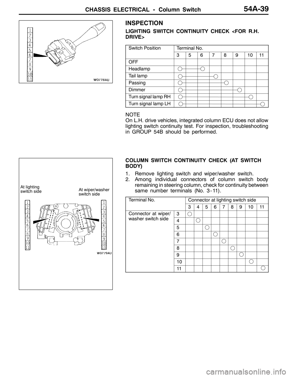
INSPECTION
LIGHTING SWITCH CONTINUITY CHECK
Switch PositionTerminal No.
3567891011
OFF
Headlamp
Tail lamp
Passing
Dimmer
Turn signal lamp RH
Turn signal lamp LH
NOTE
On L.H. drive vehicles, integrated column ECU does not allow
lighting switch continuity test. For inspection, troubleshooting
in GROUP 54B should be performed.
COLUMN SWITCH CONTINUITY CHECK (AT SWITCH
BODY)
1. Remove lighting switch and wiper/washer switch.
2. Among individual connectors of column switch body
remaining in steering column, check for continuity between
same number terminals (No. 3 - 11).
Terminal No.Connector at lighting switch side
34567891011
Connector at wiper/
hit hid
3p
washer switch side4
5
6
7
8
9
10
11
At lighting
switch sideAt wiper/washer
switch side