Page 1246 of 1449

SRS -General InformationSRS -General Information52B-2
GENERAL INFORMATION
To improve safety, the SRS and seat belts with
pre-tensioner. These systems enhance collision
safety by restraining the front passengers in case
of an accident. The SRS works with the
pre-tensioner simultaneously when a collision is
detected.
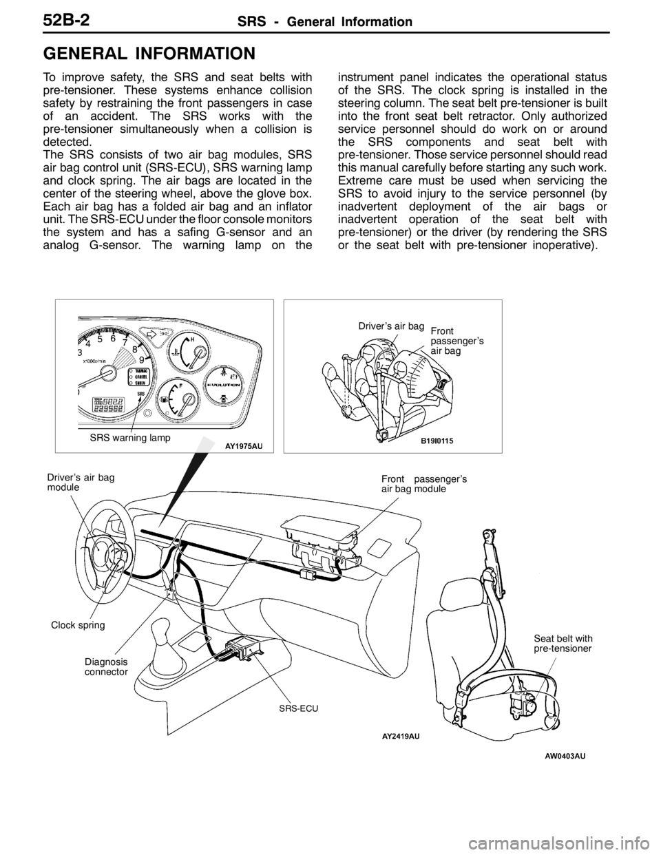
The SRS consists of two air bag modules, SRS
air bag control unit (SRS-ECU), SRS warning lamp
and clock spring. The air bags are located in the
center of the steering wheel, above the glove box.
Each air bag has a folded air bag and an inflator
unit. The SRS-ECU under the floor console monitors
the system and has a safing G-sensor and an
analog G-sensor. The warning lamp on theinstrument panel indicates the operational status
of the SRS. The clock spring is installed in the
steering column. The seat belt pre-tensioner is built
into the front seat belt retractor. Only authorized
service personnel should do work on or around
the SRS components and seat belt with
pre-tensioner. Those service personnel should read
this manual carefully before starting any such work.
Extreme care must be used when servicing the
SRS to avoid injury to the service personnel (by
inadvertent deployment of the air bags or
inadvertent operation of the seat belt with
pre-tensioner) or the driver (by rendering the SRS
or the seat belt with pre-tensioner inoperative).
Diagnosis
connectorFront passenger’s
air bag module
Clock spring Driver’s air bag
module
SRS-ECU
SRS warning lamp
Driver’s air bag
Front
passenger’s
air bag
Seat belt with
pre-tensioner
Page 1249 of 1449
SRS -Special Tools52B-5
SPECIAL TOOLS
ToolNumberNameUse
MB991502MUT-IIsub
assemblyDReading and erasing diagnosis codes
DReading trouble period
DReading erase times
MB991865Dummy resistorChecking SRS air bag circuit
MB991866Resistor harness
MB991613SRS check
harnessChecking SRS electrical circuitry
A
B
C
DMB991223
A: MB991219
B: MB991220
C: MB991221
D: MB991222Harness set
A: Check harness
B: LED harness
C: LED harness
adapter
D: ProbeChecking continuity and measuring voltage at
SRS-ECU harness connector
MB990803Steering wheel
pullerRemoving steering wheel
MR372530SRS air bag
adapter harnessDeploying driver’s air bag module inside
vehicle
Page 1256 of 1449

SRS -Troubleshooting52B-12
Code No.21 Driver’s air bag module (squib) systemPossible Cause
This code is output when short circuit occurs between terminals of the
SRS-ECU driver’s air bag module (squib) circuit.
However, SRS warning lamp goes out when a normal operation is resumed
(diagnosis code is not cleared.)DConnector engagement faulty or short bar faulty*
DShort circuit in the clock spring
DShort circuit between terminals of the driver’s air
bag module (squib) circuit
DFaulty connector
DSRS-ECU inoperable
NOTE:
(1) *: The connector of the squib circuit contains a short bar (short-circuiting the positive (+) cable and
the negative ( - ) cable to avoid an erroneous deployment caused by static electricity when a connector
is not connected). Thus, when a connector is connected, the short bar may not be released due
to improper engagement of the connector or faulty connector as shown in the illustration below.
Disconnect the connector as shown in the illustration below, then reconnect it. Check that a diagnosis
code is output again after erasing the memory. If the diagnosis code is not output, the above-mentioned
code is output due to improper engagement of the connector.
C-204C-207
SRS-ECU
Clock spring
Driver’s air bag module C-21
(2) Two different types of driver’s air bag modules by model are featured. Thus, two types of air bag
module by model are described in the following flowchart.
RS: Steering wheel and air bag module separate type
RS-II: Steering wheel and air bag module incorporate type
Page 1260 of 1449
SRS -Troubleshooting52B-16
Code No.22 Driver’s air bag module (squib) systemPossible Cause
This code is output when open circuit occurs in the SRS-ECU driver’s air bag
module (squib) circuit.
However, SRS warning lamp goes out when a normal operation is resumed
(diagnosis code is not cleared.)DOpen in the clock spring
DHalf open in the circuit due to improper neutral
positioning of the clock spring
DOpen in the driver’s air bag module (squib) circuit
DDriver’s air bag module (squib) connector falling
out
DConnector improper contact
DSRS-ECU inoperable
NOTE:
Two different types of driver’s air bag modules by model are featured. Thus, two types of air bag module
by model are described in the following flowchart.
RS: Steering wheel and air bag module separate type
RS-II: Steering wheel and air bag module incorporate type
Page 1262 of 1449

SRS -Troubleshooting52B-18
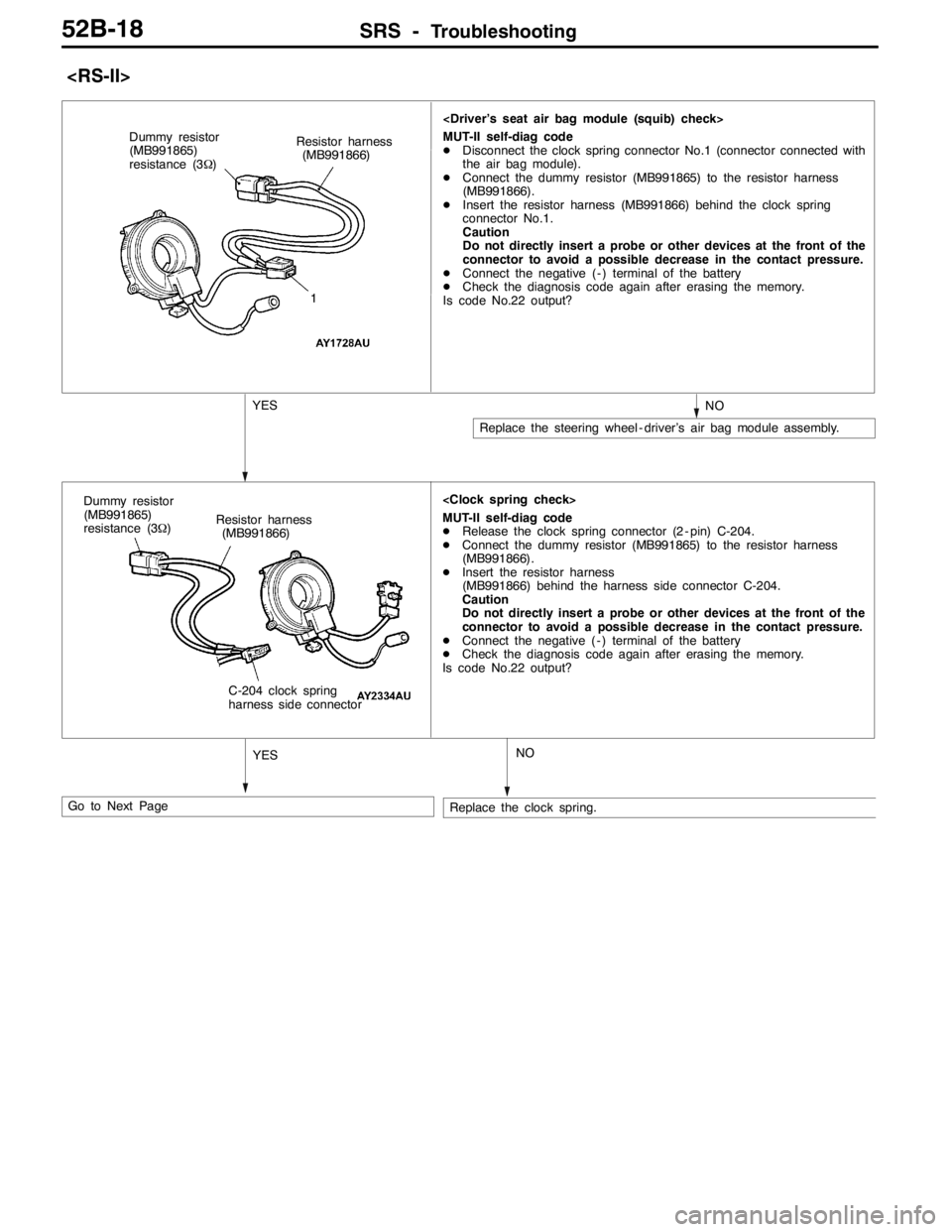
MUT-II self-diag code
DDisconnect the clock spring connector No.1 (connector connected with
the air bag module).
DConnect the dummy resistor (MB991865) to the resistor harness
(MB991866).
DInsert the resistor harness (MB991866) behind the clock spring
connector No.1.
Caution
Do not directly insert a probe or other devices at the front of the
connector to avoid a possible decrease in the contact pressure.
DConnect the negative ( - ) terminal of the battery
DCheck the diagnosis code again after erasing the memory.
Is code No.22 output? Dummy resistor
(MB991865)
resistance (3Ω)
1
YESNO
Replace the steering wheel - driver’s air bag module assembly. Resistor harness
(MB991866)
Go to Next Page
MUT-II self-diag code
DRelease the clock spring connector (2 - pin) C-204.
DConnect the dummy resistor (MB991865) to the resistor harness
(MB991866).
DInsert the resistor harness
(MB991866) behind the harness side connector C-204.
Caution
Do not directly insert a probe or other devices at the front of the
connector to avoid a possible decrease in the contact pressure.
DConnect the negative ( - ) terminal of the battery
DCheck the diagnosis code again after erasing the memory.
Is code No.22 output?
YES
Replace the clock spring.NO
Resistor harness
(MB991866)
C-204 clock spring
harness side connector Dummy resistor
(MB991865)
resistance (3Ω)
Page 1278 of 1449
SRS -Troubleshooting52B-34
Code No.61 Driver’s air bag module (squib) system
(short-circuited to power supply)Possible Cause
Code No.62 Driver’s air bag module (squib) system
(short-circuited to earth)
This code is output when the input terminal of the SRS-ECU driver’s air bag
module (squib) is short-circuited to power supply (code No.61) or short-circuited
to earth (code No.62).DClock spring fault
DHarness or connector fault
DThe harness of the driver’s air bag module (squib)
is short-circuited to power supply (code No.61) or
short-circuited to earth (code No.62)
DSRS-ECU inoperable
NOTE
Two different types of driver’s air bag modules by model are featured. Thus, two types of air bag module
by model are described in the following flowchart.
RS: Steering wheel and air bag module separate type
RS-II: Steering wheel and air bag module incorporate type
Page 1287 of 1449

SRS - SRS Maintenance52B-43
AIR BAG MODULES, STEERING WHEEL AND CLOCK
SPRING AND SEAT BELT WITH PRE-TENSIONER
1. Remove the air bag modules, steering wheel and clock
spring. (Refer to P.52B-52.)
Caution
The removed air bag modules should be stored in
a clean, dry place with the cover face up.
2. Check cover for dents, cracks or deformation.
3. Check connector for damage, terminals deformities, and
harness for binds.
4. Check air bag inflator case for dents, cracks or deformities.
5. Check harness and connectors for damage, and terminals
for deformation.
6. Check clock spring connectors and protective tube for
damage, and terminals for deformation.
7. Visually check the clock spring case for damage.
8. Align the mating marks of the clock spring and, after
turning the vehicle’s front wheels to straight-ahead
position, install the clock spring to the column switch.
Mating Mark Alignment
Turn the clock spring clockwise fully, and then turn back
it approx. 3 times counterclockwise to align the mating
marks.
Caution
If the clock spring’s mating mark is not properly
aligned, the steering wheel may not be completely
rotational during a turn, or the flat cable within the
clock spring may be severed, obstructing normal
operation of the SRS and possibly leading to serious
injury to the vehicle’s driver or front passenger.
9. Install the steering column covers, steering wheel and
the air bag module.
10. Check steering wheel for noise, binds of difficult operation.
11. Check steering wheel for excessive free play.Inflator
Connector
Connector
Steering
wheel - driver’s
air bag module
assembly
Connector Inflator case
Mating marks
Page 1290 of 1449

SRS - Post-collision Diagnosis52B-46
REPAIR PROCEDURE
DEPLOYED DRIVER’S AND FRONT PASSENGER’S AIR
BAGS OR OPERATED SEAT BELT PRE-TENSIONER.
1. Replace the following parts with new ones.
DSRS-ECU (Refer to P.52B-50.)
DDriver’s air bag module (Refer to P.52B-52.)
DFront passenger’s air bag module (Refer to P.52B-52.)
DSeat belt with pre-tensioner (Refer to P.52B-61.)
2. Check the following parts and replace if malfunction is
found:
DClock spring (Refer to P.52B-52.)
DSteering wheel, steering column and intermediate
joint
(1) Check the wiring harness (built into steering
wheel) and connectors for damage, and terminals
for deformation.
(2) Check the driver’s air bag module for proper
installation to the steering wheel.
(3) Check the steering wheel for noise, binds or
difficult operation and excessive free play.
3. Check the harness for binding, connectors for damage,
poor connections, and terminals for deformation.
(Refer to P.52B-44.)
UNDEPLOYED AIR BAGS OR UNOPERATED SEAT BELT
WITH PRE-TENSIONER IN LOW-SPEED COLLISION
Check the SRS components and seat belt with pre-tensioner.
If visible damage such as dents, cracks, or deformation are
found on the SRS components and seat belt with
pre-tensioner, replace them with new ones. Concerning parts
removed for inspection, replacement with new parts and
cautions in working, refer to INDIVIDUAL COMPONENT
SERVICE, P.52B-49.