Page 1379 of 1575
3.Select "POWER TAIL GATE".
4.Select the sensor output. And then check the optical sensor volt while operating power tailgate in power mode.
5.Change the drive unit, if there is no change during operation.
DRIVE UNIT CLUTCH INSPECTION
1.Check the power tailgate control module input/output value by using the diagnostic tool. If the operation of tailgate
control module is abnormal, replace power tailgate drive unit.
2. To check the clutch operation, select a vehicle type and "POWER SLIDING/TAILGATE" menu.
3.Select power tailgate.
Page 1380 of 1575
4.Select the sensor output. And then check the clutch feedback sensor output while operating power tailgate in
power mode.
※ Above voltage and numerical value may be different from the real value.
5. Change the drive unit, if there is no change during operation.
REPLACEMENT
1.Disconnect the negative ( - ) battery terminal.
2. Remove the third, fourth seat (Refer to the Body group - seat)
3. Remove the D pillar and luggage side trim (Refer to the Body group - Interior trim).
4. Use a small screw driver to loosen clip (A). But do not remove power tailgate push rod (B).
5.Remove the power tail gate motor mounting bolts (3EA) and connectors (4EA). And then remove the power tail
gate drive unit(A).
TORQUE : 22- 27N.m(2.2- 2.7Kg.m)
Page 1459 of 1575

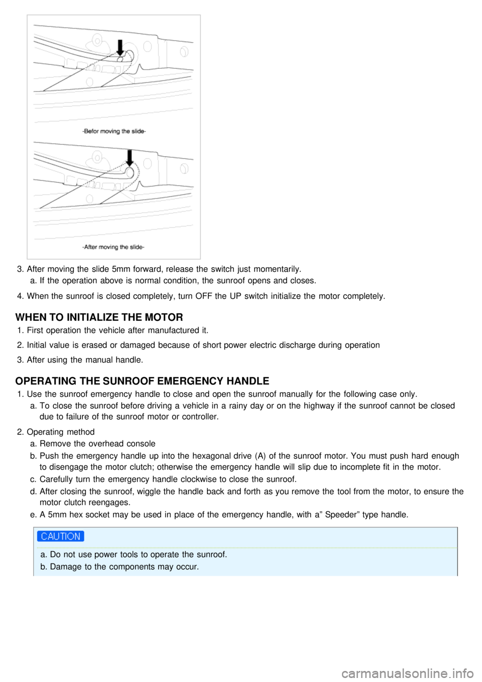
3.After moving the slide 5mm forward, release the switch just momentarily.
a. If the operation above is normal condition, the sunroof opens and closes.
4. When the sunroof is closed completely, turn OFF the UP switch initialize the motor completely.
WHEN TO INITIALIZE THE MOTOR
1.First operation the vehicle after manufactured it.
2. Initial value is erased or damaged because of short power electric discharge during operation
3. After using the manual handle.
OPERATING THE SUNROOF EMERGENCY HANDLE
1.Use the sunroof emergency handle to close and open the sunroof manually for the following case only.
a. To close the sunroof before driving a vehicle in a rainy day or on the highway if the sunroof cannot be closed
due to failure of the sunroof motor or controller.
2. Operating method
a. Remove the overhead console
b. Push the emergency handle up into the hexagonal drive (A) of the sunroof motor. You must push hard enough
to disengage the motor clutch; otherwise the emergency handle will slip due to incomplete fit in the motor.
c. Carefully turn the emergency handle clockwise to close the sunroof.
d. After closing the sunroof, wiggle the handle back and forth as you remove the tool from the motor, to ensure the
motor clutch reengages.
e. A 5mm hex socket may be used in place of the emergency handle, with a” Speeder” type handle.
a.Do not use power tools to operate the sunroof.
b. Damage to the components may occur.
Page 1561 of 1575
CHAPTER 16:
Clutch System
Page 1562 of 1575
2007 > 2.7L V6 GASOLINE >
DESCRIPTION
SELF ADJUSTING CLUTCH(S.A.C.) COVER
a. As a clutch disc facing is worn away according to its durability, a cover weight is increasing and a clutch pedal
pressure can be more needed.
b. To make up for this defect, the self adjusting clutch system makes the requsted pedal pressure minimized so that
makes the maintenance cycle longer.
CONCENTRIC SLAVE CYLINDER-C.S.C.
It improves working efficiency and lowers the number and the weight of part by unifing clutch release control
parts(clutch release bearing ~ clutch release cylinder) in a manual transaxle.
OPERATION
CONCENTRIC SLAVE CYLINDER-C.S.C
When the clutch pedal is pressed, oil pressure is transmitted along the arrow directions shown below and that moves
the clutch slave cylinder and the diaphragm spring of the clutch cover.
Page 1564 of 1575
Page 1566 of 1575

2007 > 2.7L V6 GASOLINE >
REPLACEMENT
1.Remove a transaxle assembly (refer to 'MT'- group).
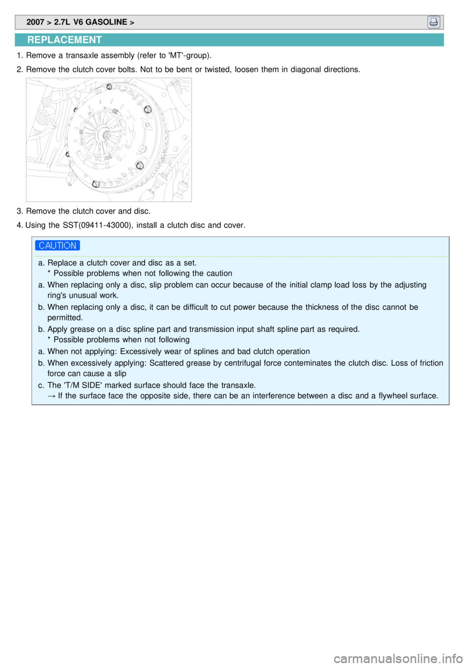
2. Remove the clutch cover bolts. Not to be bent or twisted, loosen them in diagonal directions.
3.Remove the clutch cover and disc.
4. Using the SST(09411- 43000), install a clutch disc and cover.
a. Replace a clutch cover and disc as a set.
* Possible problems when not following the caution
a. When replacing only a disc, slip problem can occur because of the initial clamp load loss by the adjusting
ring's unusual work.
b. When replacing only a disc, it can be difficult to cut power because the thickness of the disc cannot be
permitted.
b. Apply grease on a disc spline part and transmission input shaft spline part as required.
* Possible problems when not following
a. When not applying: Excessively wear of splines and bad clutch operation
b. When excessively applying: Scattered grease by centrifugal force conteminates the clutch disc. Loss of friction
force can cause a slip
c. The 'T/M SIDE' marked surface should face the transaxle.
→ If the surface face the opposite side, there can be an interference between a disc and a flywheel surface.
Page 1567 of 1575
5.Tighten the clutch cover.
TORQUE:
24.5~35.3Nm (250~360kgf.cm, 18.1~26.0lb - ft) (6EA)
When installing the clutch cover, tighten the bolts in diagonal directions not to be bent or twisted.
* Possible problems when not following
a. When tightening the bolt completely at a time: the clutch cover can be twisted and vibration can occur.
b. On vehicles with self adjusting clutches, it is necessary to follow this caution.
c. Not following tightening torque: There can be bad torque transmission in clutch and relaxation possibility of
bolts.
INSPECTION
1.Inspect diaphragm spring wear which is in contact with a concentric slave cylinder bearing.