2007 KIA CARNIVAL clutch
[x] Cancel search: clutchPage 661 of 1575

volume, Subtract the volume of drained oil from 120cc(4.20 oz.) the result is the amount of oil you should drain
from the new compressor (through the suction fitting).
b. Replace the O - rings with new ones at each fitting, and apply a thin coat of refrigerant oil before installing them.
Be sure to use the right O - rings for R- 134a to avoid leakage.
c. To avoid contamination, do not return the oil to the container once dispensed, and never mix it with other
refrigerant oils.
d. Immediately after using the oil, replace the cap on the container and seal it to avoid moisture absorption.
e. Do not spill the refrigerant oil on the vehicle; it may damage the paint; if the refrigerant oil contacts the paint,
wash it off immediately.
f. Adjust the drive belt (Refer to HA - 14)
g. Charge the system and test its performance. (Refer to HA - 9)
INSPECTION
1.Check the plated parts of the disc & hub assembly (A) for color changes, peeling or other damage. If there is
damage, replace the clutch set.
2. Check the pulley (B) bearing play and drag by rotating the pulley by hand. Replace the clutch set with a new one if
it is noisy or has excessive play/drag.
3.Measure the clearance between the pulley (B) and the disc & hub assembly (A) all the way around. If the
clearance is not within specified limits, remove the disc & hub assembly and add or remove shim (gap washer) as
needed to increase or decrease clearance.
Clearance: 0.45 ± 0.1mm (0.018 ± 0.004 in.)
The shims (gap washers) are available in seven thicknesses: 0.7mm, 0.8mm, 0.9mm, 1.0mm, 1.1mm, 1.2mm
and 1.3mm.
Page 662 of 1575

4.Check operation of the magnetic clutch.Connect the compressor side terminals to the battery (+) terminal and the
ground battery ( - ) terminal to the compressor body.
Check the magnetic clutch operating noise to determine the condition.
DISASSEMBLY
1.Remove the center bolt (A) while holding the disc & hub assembly with a commercially available disc & hub
assembly bolt remover; Special tool number 09977 - 29000.
TORQUE: 10~15N.m (1.02~1.53kgf.m, 7.37~11lbf.ft)
2.Remove the disc & hub assembly (A) and shim (gap washer) (B), taking care not to lose the shims. If the clutch
needs adjustment, increase or decrease the number and thickness of shims as necessary, then reinstall the disc &
hub assembly, and recheck its clearance (Refer to HA - 19).
3.If you removal the field coil, remove retainer ring (A) with retainer ring pliers.
a.Be careful not to damage the pulley (B) and compressor during removal/installation.
b. Once retainer ring (A) is removed, replace it with a new one.
Page 663 of 1575

4.Remove the screw (A) from the field coil ground terminal. Remove the retainer ring (B) and then remove the field
coil (C) from the shaft with a puller. Be careful not to damage the coil and compressor.
5.Reassemble the compressor clutch in the reverse order of disassembly, and note these items :
a. Clean the pulley and compressor sliding surfaces with non- petroleum solvent.
b. Install new retainer rings, and make sure they are fully seated in the groove.
c. Make sure that the pulley turns smoothly after its reassembled.
Page 993 of 1575

2007 > 2.7L V6 GASOLINE >
TROUBLESHOOTING
Symptom Suspect AreaRemedy (See page)
Water leaks from sunroof Dirt accumulated in drain tube Clear dirt inside of drain
Clogged drain tube Blow air into drain to remove dirt
Broken or dislocated drain tube, defective
Or cracked clip Check tube installation and
Flange contact
Deteriorated roof lid weatherstrip Replace
Excessive roof lid - to- body clearance and
Improperly fitted weatherstrip Adjust
Wind noise around sunroof Loose or deformed deflector, gaps
In body work Retighten adjust or replace
Sunroof lid makes a noise when
moveing Foreign particles lodged in guide rail
Check drive cable and guide
Rails for foreign particles
Loose guide rails and lid Retighten
Motor runs but sunroof does not
move or moves only partially Foreign particles lodged in guide rail
Check drive cable and guide
Rails for foreign particles
Incorrect engagement of motor pinion
With drive cable Check for loose motor installation
And damaged pinion
Decrease in motor`s clutch slipping force Adjust
Increased sunroof sliding resistance
Or interference of sunroof with drive
cables, weatherstrip, etc. due to
maladjustment of sunroof Adjust or replace
Noise in motor (clutch slipping
Noise from motor when sunroof
Is fully opened or closed is not
An unusual noise Incorrect engagement of motor pinion
With drive cable
Check pinion installation and
Retighten motor
Worn out or damaged motor pinion bearing Replace motor assembly
Worn out or deformed drive cable Replace
Door glass fails to operate
Up and down Incorrect window glass installation
Adjust position
Damaged or faulty regulator arm or regulator Correct or replace
Door does not open or close
completely Incorrect door installation
Adjust position
Defective door check assembly Correct or replace
Door hinge requires grease Apply grease
Hood does not open or close
completely Striker and latch not properly aligned
Adjust
Incorrectly installed hood Adjust
Incorrect hood bumper height Adjust
Water leak through windshield
end rear window Defective seal
Fill with sealant
Defective flange Correct
Page 1307 of 1575

2007 > 2.7L V6 GASOLINE >
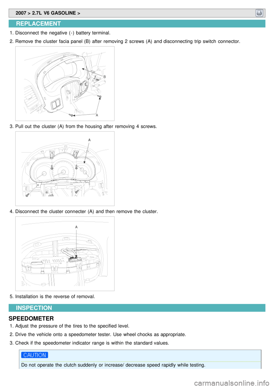
REPLACEMENT
1.Disconnect the negative ( - ) battery terminal.
2. Remove the cluster facia panel (B) after removing 2 screws (A) and disconnecting trip switch connector.
3.Pull out the cluster (A) from the housing after removing 4 screws.
4.Disconnect the cluster connecter (A) and then remove the cluster.
5.Installation is the reverse of removal.
INSPECTION
SPEEDOMETER
1. Adjust the pressure of the tires to the specified level.
2. Drive the vehicle onto a speedometer tester. Use wheel chocks as appropriate.
3. Check if the speedometer indicator range is within the standard values.
Do not operate the clutch suddenly or increase/ decrease speed rapidly while testing.
Page 1323 of 1575

2007 > 2.7L V6 GASOLINE >
DESCRIPTION
Power Sliding Door is an electro - mechanical system designed to provide power opening and closing of a vehicle's
sliding door through the push of a button of the transmitter key or the main control buttons on the overhead console
or the sub control buttons on the center pillar trim or inside/outside door handle switch.
The power sliding door will reverse direction of travel if resistance to movement is detected while the door is being
closed. If resistance to movement is detected while the power sliding door is being opened, the door will stop moving.
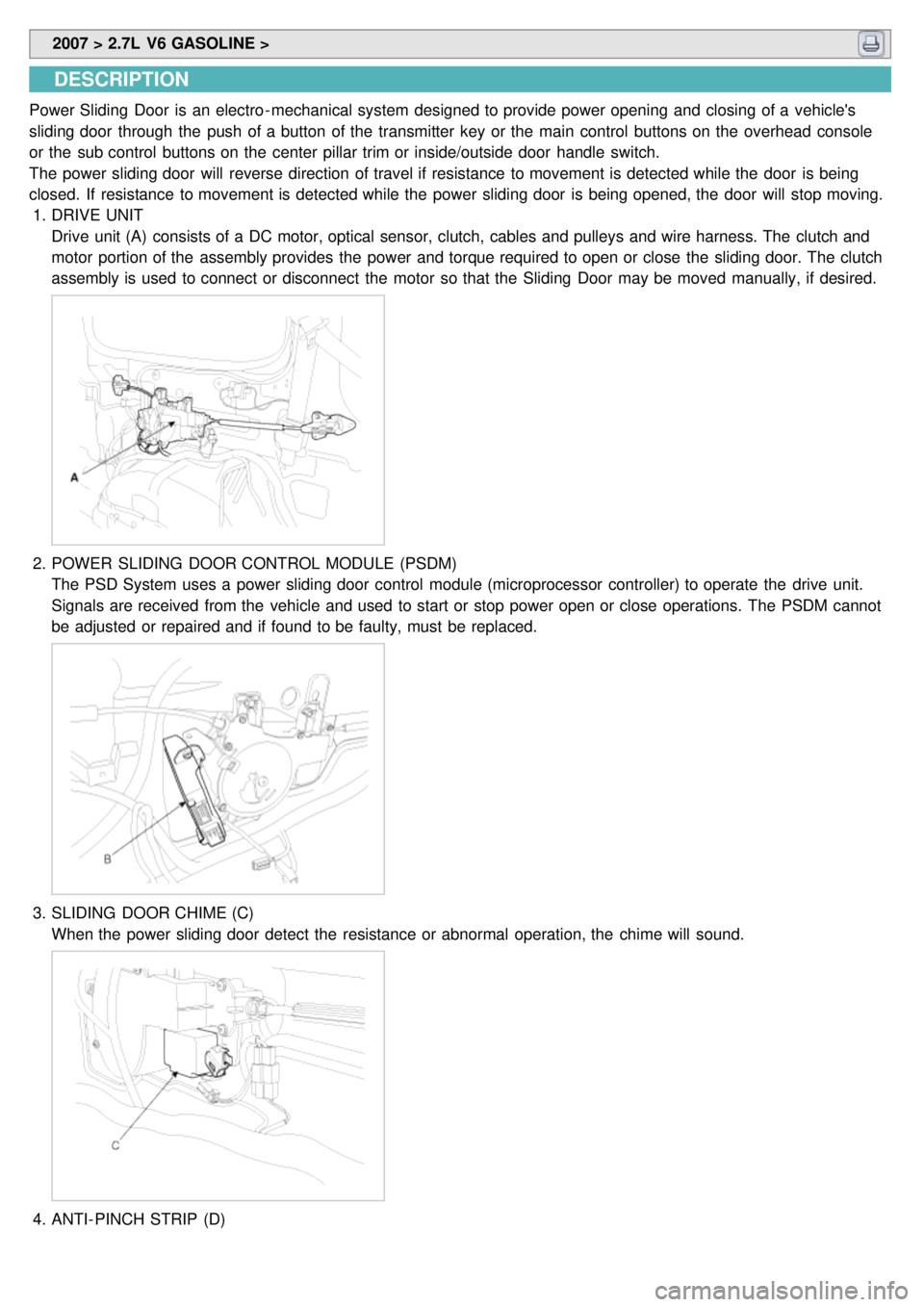
1. DRIVE UNIT
Drive unit (A) consists of a DC motor, optical sensor, clutch, cables and pulleys and wire harness. The clutch and
motor portion of the assembly provides the power and torque required to open or close the sliding door. The clutch
assembly is used to connect or disconnect the motor so that the Sliding Door may be moved manually, if desired.
2.POWER SLIDING DOOR CONTROL MODULE (PSDM)
The PSD System uses a power sliding door control module (microprocessor controller) to operate the drive unit.
Signals are received from the vehicle and used to start or stop power open or close operations. The PSDM cannot
be adjusted or repaired and if found to be faulty, must be replaced.
3.SLIDING DOOR CHIME (C)
When the power sliding door detect the resistance or abnormal operation, the chime will sound.
4.ANTI- PINCH STRIP (D)
Page 1333 of 1575

Wiring problems (system or vehicle)Refer to wiring diagrams
Check for diagnostic trouble codes.
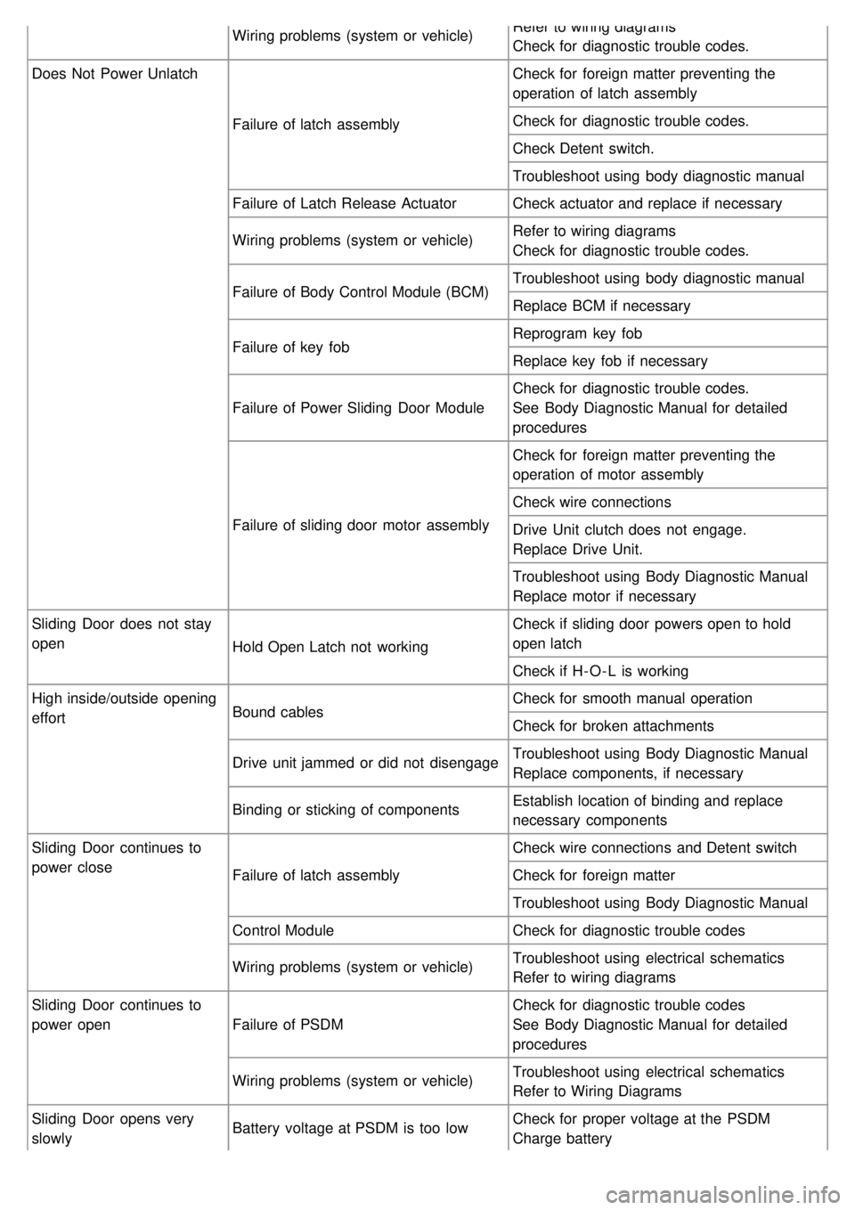
Does Not Power Unlatch
Failure of latch assembly Check for foreign matter preventing the
operation of latch assembly
Check for diagnostic trouble codes.
Check Detent switch.
Troubleshoot using body diagnostic manual
Failure of Latch Release Actuator Check actuator and replace if necessary
Wiring problems (system or vehicle) Refer to wiring diagrams
Check for diagnostic trouble codes.
Failure of Body Control Module (BCM) Troubleshoot using body diagnostic manual
Replace BCM if necessary
Failure of key fob Reprogram key fob
Replace key fob if necessary
Failure of Power Sliding Door Module Check for diagnostic trouble codes.
See Body Diagnostic Manual for detailed
procedures
Failure of sliding door motor assembly Check for foreign matter preventing the
operation of motor assembly
Check wire connections
Drive Unit clutch does not engage.
Replace Drive Unit.
Troubleshoot using Body Diagnostic Manual
Replace motor if necessary
Sliding Door does not stay
open Hold Open Latch not working Check if sliding door powers open to hold
open latch
Check if H- O - L is working
High inside/outside opening
effort Bound cables Check for smooth manual operation
Check for broken attachments
Drive unit jammed or did not disengage Troubleshoot using Body Diagnostic Manual
Replace components, if necessary
Binding or sticking of components Establish location of binding and replace
necessary components
Sliding Door continues to
power close Failure of latch assembly Check wire connections and Detent switch
Check for foreign matter
Troubleshoot using Body Diagnostic Manual
Control Module Check for diagnostic trouble codes
Wiring problems (system or vehicle) Troubleshoot using electrical schematics
Refer to wiring diagrams
Sliding Door continues to
power open Failure of PSDM Check for diagnostic trouble codes
See Body Diagnostic Manual for detailed
procedures
Wiring problems (system or vehicle) Troubleshoot using electrical schematics
Refer to Wiring Diagrams
Sliding Door opens very
slowly Battery voltage at PSDM is too low
Check for proper voltage at the PSDM
Charge battery
Page 1334 of 1575

Bound cablesReplace drive unit if necessary
Binding or sticking of components Establish location of binding and replace
necessary components
Grade of vehicle too steep for power
operation Operate sliding door manually
Failure of sliding door motor assembly Replace motor assembly, if necessary
Squeaks, Noises and rattles Foreign material in Sliding Door Remove foreign material
Worn or Loose components Check and tighten loose components
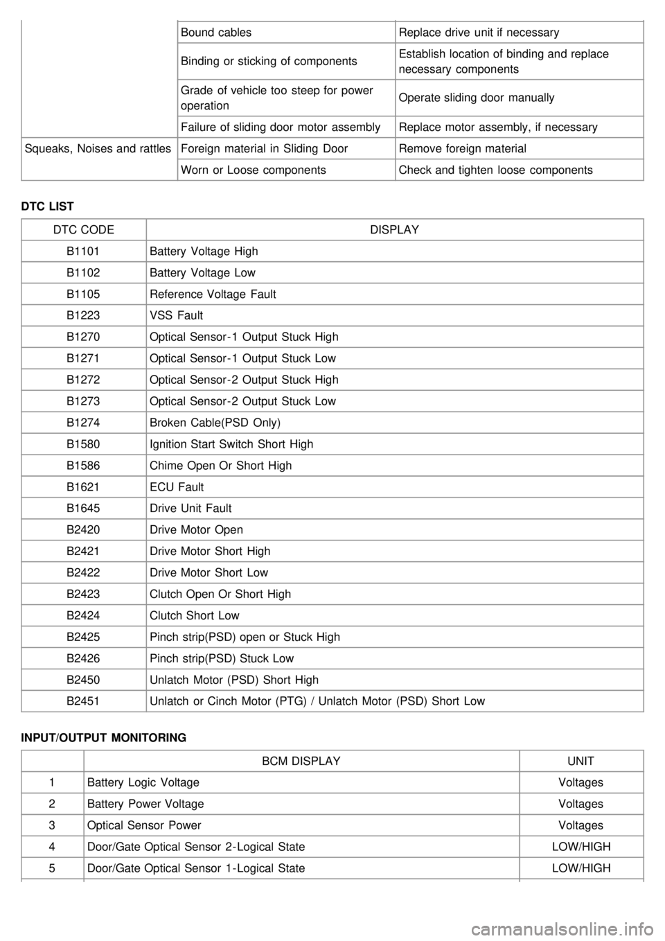
DTC LIST DTC CODE DISPLAY
B1101 Battery Voltage High
B1102 Battery Voltage Low
B1105 Reference Voltage Fault
B1223 VSS Fault
B1270 Optical Sensor - 1 Output Stuck High
B1271 Optical Sensor - 1 Output Stuck Low
B1272 Optical Sensor - 2 Output Stuck High
B1273 Optical Sensor - 2 Output Stuck Low
B1274 Broken Cable(PSD Only)
B1580 Ignition Start Switch Short High
B1586 Chime Open Or Short High
B1621 ECU Fault
B1645 Drive Unit Fault
B2420 Drive Motor Open
B2421 Drive Motor Short High
B2422 Drive Motor Short Low
B2423 Clutch Open Or Short High
B2424 Clutch Short Low
B2425 Pinch strip(PSD) open or Stuck High
B2426 Pinch strip(PSD) Stuck Low
B2450 Unlatch Motor (PSD) Short High
B2451 Unlatch or Cinch Motor (PTG) / Unlatch Motor (PSD) Short Low
INPUT/OUTPUT MONITORING BCM DISPLAY UNIT
1 Battery Logic Voltage Voltages
2 Battery Power Voltage Voltages
3 Optical Sensor Power Voltages
4 Door/Gate Optical Sensor 2 - Logical State LOW/HIGH
5 Door/Gate Optical Sensor 1 - Logical State LOW/HIGH