2007 KIA CARNIVAL washer fluid
[x] Cancel search: washer fluidPage 424 of 1575

2007 > 2.7L V6 GASOLINE >
SERVICE ADJUSTMENT PROCEDURE
Transmission oil inspection and replacement
1. After parking the vehicle on a plain, stop the engine.
2. After removing the oil filler plug and washer, inspect the manual transaxle fluid condition and quantity.
3. If the manual transaxle fluid is contaminated, drain it out by removing the oil drain plug.
4. Tighten the new oil drain plug and feed manual transaxle fluid to a proper level.
TORQUE:
29.4~34.4 Nm(3.0~3.5kgf.m, 21.7~25.3lb - ft)
Oil type: SAE75W/85
Oil quantity:
1.9 liter(2.0077 US qt, 1.6718 lmp qt)
5. Retighten the oil filler plug with a new washer.
TORQUE:
29.4~34.4 Nm(3.0~3.5kgf.m, 21.7~25.3lb - ft)
Back up lamp switch inspection
1.Disconnect the back up lamp switch connector(B).
2.Inspect the continuity of the switch. When the shift lever is located in reverse range, it should be applied an electric
current.
3. Replace the back up lamp switch, if necessary.
TORQUE:
29.4~34.4 Nm(3.0~3.5kgf.m, 21.7~25.3lb - ft)
Page 605 of 1575

Check for rust on the rack when the bellows are replaced.
6. Remove the feed tube(A) from the rack housing.
7.While moving the rack slowly, drain the fluid from the rack housing.
8. Unstake the tab washer (A) which fixes the tie rod (B) and rack (C) with a chisel.
9.Remove the tie rod (B) from the rack (A).
Remove the tie rod (B) from the rack (A), taking care not to twist the rack.
10. Remove the yoke plug locking nut (A).
Page 609 of 1575

(4)Check for oil seal ring damage or wear.
(5) Check for oil seal damage or wear.
2.Pinion valve
(1) Check for pinion gear tooth face damage or wear.
(2) Check for oil seal contact surface damage.
(3) Check for seal ring damage or wear.
(4) Check for oil seal damage or wear.
3.Bearing
(1) Check for seizure or abnormal noise during abearing rotation.
(2) Check for excessive play.
(3) Check for missing needle bearing rollers.
4. Others
(1) Check for damage of the rack housing cylinder bore.
(2) Check for boot damage, cracking or aging.
REASSEMBLY
1.Apply the specified fluid to the entire surface of the rack oil seal.
Recommended fluid : PSF - 3
2. Install the backup washer and oil seal (A) to the specified position in the rack housing.
Page 882 of 1575

5.Remove the brake fluid from the master cylinder reservoir (C) with a syringe.
6. Disconnect the brake lines (A) from the master cylinder. To prevent spills, cover the hose joints with rags or shop
towels.
7. Remove the master cylinder mounting nuts (B) and washers.
[LHD]
[RHD]
8.Remove the master cylinder(C) from the brake booster. Be careful not to bend or damage the brake lines when
removing the master cylinder.
INSTALLATION
1.Install the master cylinder on the brake booster with 2 nuts.
2. Connect the two brake tubes and the brake fluid level sensor connector.
[LHD]
Page 1227 of 1575

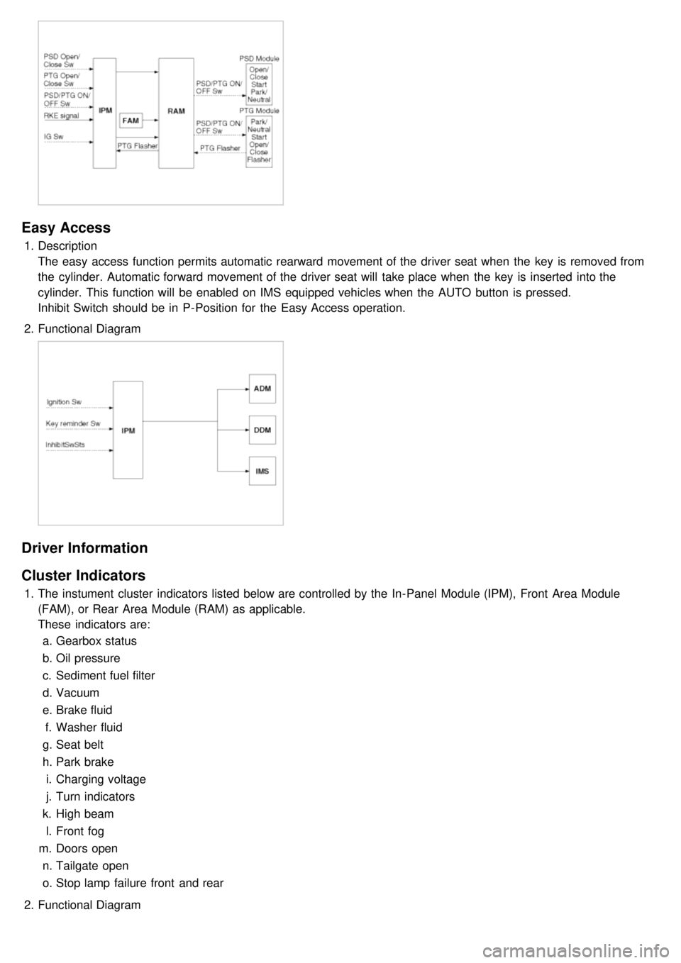
Easy Access
1.Description
The easy access function permits automatic rearward movement of the driver seat when the key is removed from
the cylinder. Automatic forward movement of the driver seat will take place when the key is inserted into the
cylinder. This function will be enabled on IMS equipped vehicles when the AUTO button is pressed.
Inhibit Switch should be in P- Position for the Easy Access operation.
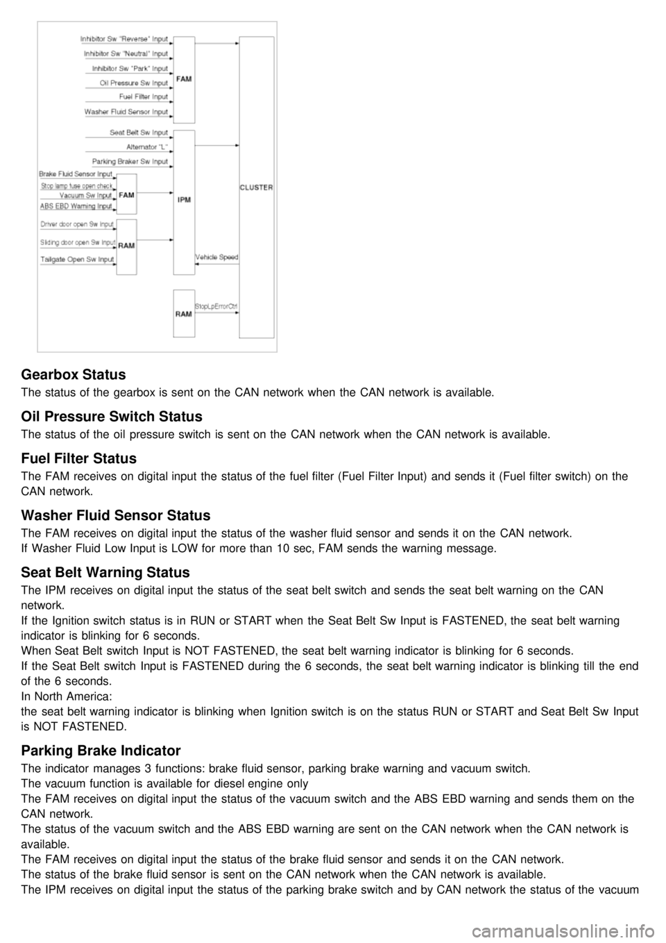
2. Functional Diagram
Driver Information
Cluster Indicators
1.The instument cluster indicators listed below are controlled by the In- Panel Module (IPM), Front Area Module
(FAM), or Rear Area Module (RAM) as applicable.
These indicators are:
a. Gearbox status
b. Oil pressure
c. Sediment fuel filter
d. Vacuum
e. Brake fluid
f. Washer fluid
g. Seat belt
h. Park brake
i. Charging voltage
j. Turn indicators
k. High beam
l. Front fog
m. Doors open
n. Tailgate open
o. Stop lamp failure front and rear
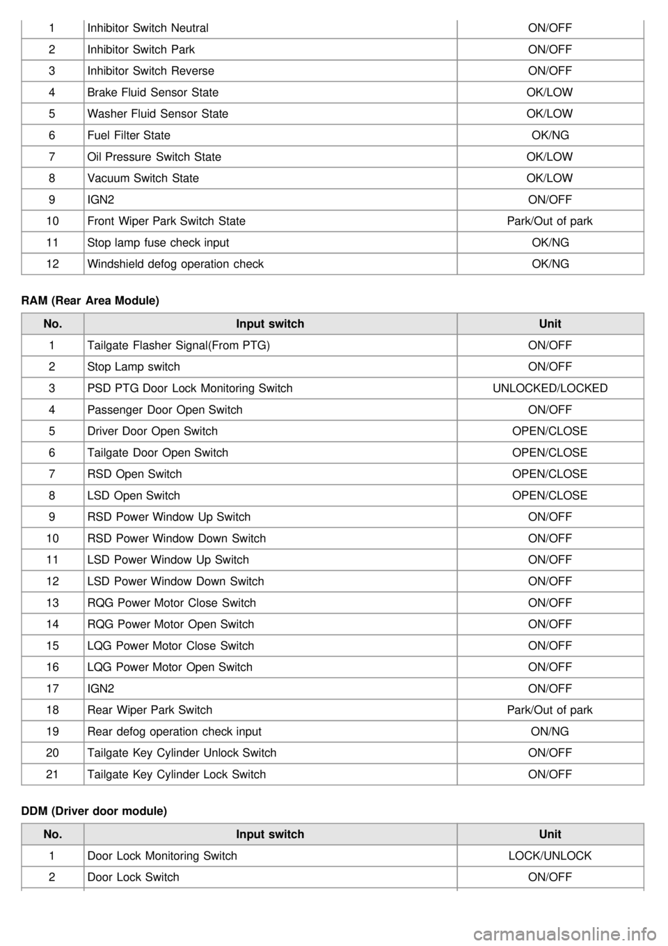
2. Functional Diagram
Page 1228 of 1575

Gearbox Status
The status of the gearbox is sent on the CAN network when the CAN network is available.
Oil Pressure Switch Status
The status of the oil pressure switch is sent on the CAN network when the CAN network is available.
Fuel Filter Status
The FAM receives on digital input the status of the fuel filter (Fuel Filter Input) and sends it (Fuel filter switch) on the
CAN network.
Washer Fluid Sensor Status
The FAM receives on digital input the status of the washer fluid sensor and sends it on the CAN network.
If Washer Fluid Low Input is LOW for more than 10 sec, FAM sends the warning message.
Seat Belt Warning Status
The IPM receives on digital input the status of the seat belt switch and sends the seat belt warning on the CAN
network.
If the Ignition switch status is in RUN or START when the Seat Belt Sw Input is FASTENED, the seat belt warning
indicator is blinking for 6 seconds.
When Seat Belt switch Input is NOT FASTENED, the seat belt warning indicator is blinking for 6 seconds.
If the Seat Belt switch Input is FASTENED during the 6 seconds, the seat belt warning indicator is blinking till the end
of the 6 seconds.
In North America:
the seat belt warning indicator is blinking when Ignition switch is on the status RUN or START and Seat Belt Sw Input
is NOT FASTENED.
Parking Brake Indicator
The indicator manages 3 functions: brake fluid sensor, parking brake warning and vacuum switch.
The vacuum function is available for diesel engine only
The FAM receives on digital input the status of the vacuum switch and the ABS EBD warning and sends them on the
CAN network.
The status of the vacuum switch and the ABS EBD warning are sent on the CAN network when the CAN network is
available.
The FAM receives on digital input the status of the brake fluid sensor and sends it on the CAN network.
The status of the brake fluid sensor is sent on the CAN network when the CAN network is available.
The IPM receives on digital input the status of the parking brake switch and by CAN network the status of the vacuum
switch, the status of the ABS EBD warning, the status of the brake fluid sensor and the speed of the vehicle.
Page 1242 of 1575

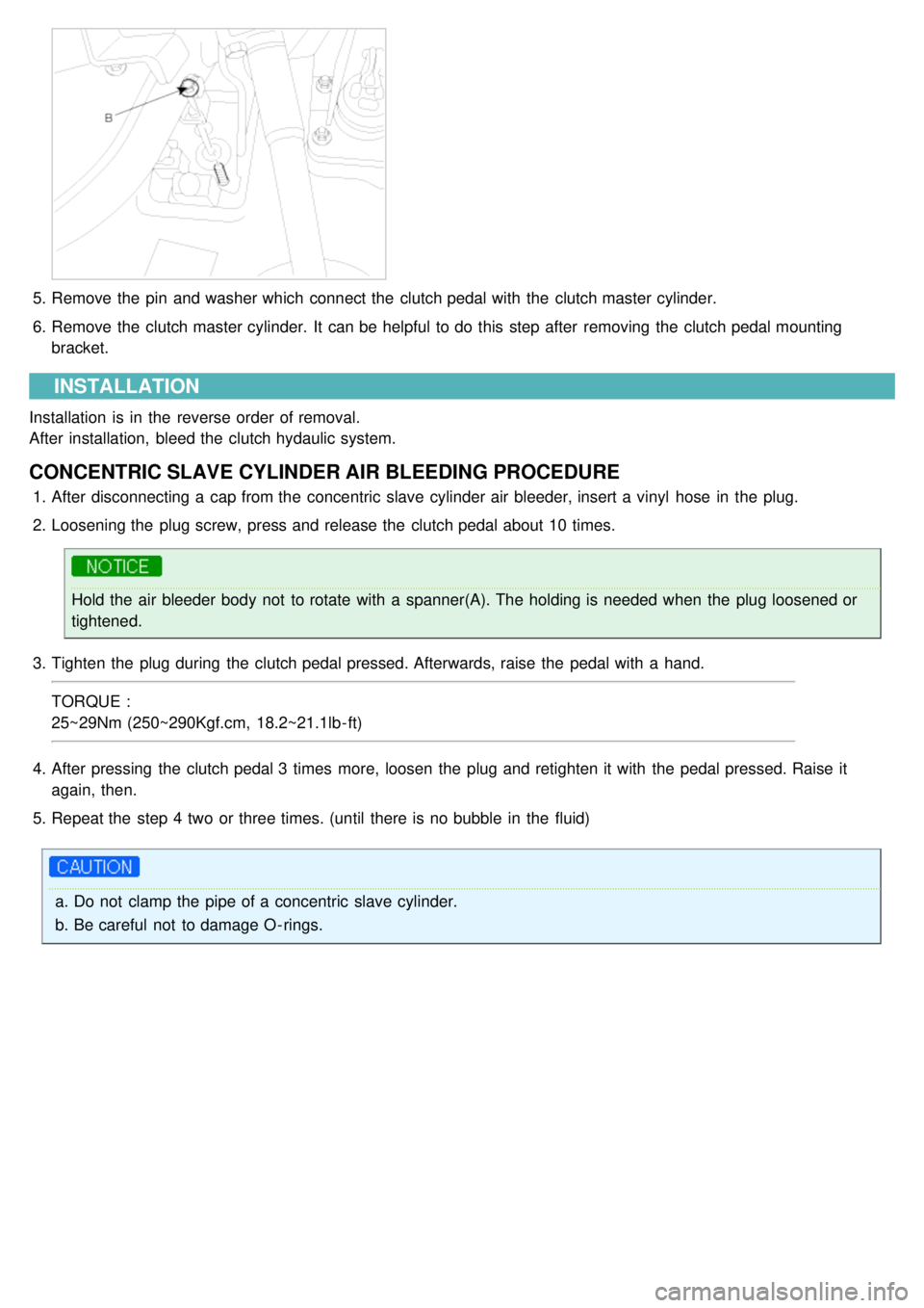
1Inhibitor Switch Neutral ON/OFF
2 Inhibitor Switch Park ON/OFF
3 Inhibitor Switch Reverse ON/OFF
4 Brake Fluid Sensor State OK/LOW
5 Washer Fluid Sensor State OK/LOW
6 Fuel Filter State OK/NG
7 Oil Pressure Switch State OK/LOW
8 Vacuum Switch State OK/LOW
9 IGN2 ON/OFF
10 Front Wiper Park Switch State Park/Out of park
11 Stop lamp fuse check input OK/NG
12 Windshield defog operation check OK/NG
RAM (Rear Area Module) No. Input switch Unit
1 Tailgate Flasher Signal(From PTG) ON/OFF
2 Stop Lamp switch ON/OFF
3 PSD PTG Door Lock Monitoring Switch UNLOCKED/LOCKED
4 Passenger Door Open Switch ON/OFF
5 Driver Door Open Switch OPEN/CLOSE
6 Tailgate Door Open Switch OPEN/CLOSE
7 RSD Open Switch OPEN/CLOSE
8 LSD Open Switch OPEN/CLOSE
9 RSD Power Window Up Switch ON/OFF
10 RSD Power Window Down Switch ON/OFF
11 LSD Power Window Up Switch ON/OFF
12 LSD Power Window Down Switch ON/OFF
13 RQG Power Motor Close Switch ON/OFF
14 RQG Power Motor Open Switch ON/OFF
15 LQG Power Motor Close Switch ON/OFF
16 LQG Power Motor Open Switch ON/OFF
17 IGN2 ON/OFF
18 Rear Wiper Park Switch Park/Out of park
19 Rear defog operation check input ON/NG
20 Tailgate Key Cylinder Unlock Switch ON/OFF
21 Tailgate Key Cylinder Lock Switch ON/OFF
DDM (Driver door module) No. Input switch Unit
1 Door Lock Monitoring Switch LOCK/UNLOCK
2 Door Lock Switch ON/OFF
Page 1571 of 1575

5.Remove the pin and washer which connect the clutch pedal with the clutch master cylinder.
6. Remove the clutch master cylinder. It can be helpful to do this step after removing the clutch pedal mounting
bracket.
INSTALLATION
Installation is in the reverse order of removal.
After installation, bleed the clutch hydaulic system.
CONCENTRIC SLAVE CYLINDER AIR BLEEDING PROCEDURE
1.After disconnecting a cap from the concentric slave cylinder air bleeder, insert a vinyl hose in the plug.
2. Loosening the plug screw, press and release the clutch pedal about 10 times.
Hold the air bleeder body not to rotate with a spanner(A). The holding is needed when the plug loosened or
tightened.
3. Tighten the plug during the clutch pedal pressed. Afterwards, raise the pedal with a hand.
TORQUE :
25~29Nm (250~290Kgf.cm, 18.2~21.1lb - ft)
4. After pressing the clutch pedal 3 times more, loosen the plug and retighten it with the pedal pressed. Raise it
again, then.
5. Repeat the step 4 two or three times. (until there is no bubble in the fluid)
a.Do not clamp the pipe of a concentric slave cylinder.
b. Be careful not to damage O - rings.