2007 KIA CARNIVAL seat adjustment
[x] Cancel search: seat adjustmentPage 12 of 1575

2007 > 2.7L V6 GASOLINE >
Compression pressure inspection
If the there is lack of power, excessive oil consumption or poor fuel economy, measure the compression
pressure.
1. Warm up the engine until the normal operating temperature becoming 80~95°C(176~203°F).
2. Remove the surge tank.
3. Remove the ignition coil connectors(B) and ignition coils.
4.Using a 16mm plug wrench, remove the 6 spark plugs.
5. Check cylinder compression pressure.
(1) Insert a compression gauge into the spark plug hole.
(2) Open the throttle fully.
(3) With the fully - open throttle in cranking, measure the compression pressure.
Always use a fully charged battery to get the engine speed of 250 rpm or more.
Repeat steps 1) through 3) for each cylinder.
This measurement must be done in as short a time as possible.
Compression pressure: 1,176.79kPa (12.0kgf/cm², 170.68psi) - 200 ~ 250rpm
Minimum pressure: 1,029.69kPa (10.5kgf/cm², 149.34psi)
Difference between cylinders: 98.07kPa (1.0kgf/cm², 14.22psi)
(4) If the compression pressure in 1 or more cylinders is lower than the specification above, pour a small amount
of engine oil into the cylinder through the spark plug hole, repeat the steps (1) through (3) for the cylinder and
measure the pressure again.
a. If adding oil increases the pressure up, the piston rings or cylinder bores might be worn or damaged.
b. If the pressure doesn't increase, a valve may be sticking or seating may be improper, or there may be
leakage from the gasket.
6. Reinstall the spark plugs.
7. Install the ignition coils and connect ignition coil connectors.
8. Install the surge tank.
VALVE CLEARANCE INSPECTION AND ADJUSTMENT
Inspect and adjust the valve clearance when the engine is cold (Engine coolant temperature : 20°C
±5°C(59~77°F)) and cylinder head is installed on the cylinder block.
Page 501 of 1575

a.Substitute a known good set of wheels and tires.
b. Perform a road test.
c. If the vehicle still exhibits a shake or vibration, note the vehicle speed
and/or engine rpm which it occurs.
● Is the vibration felt ?
→ YES
Engine/transmission imbalance.
See the specification of TR group, EM group, FL group and EC group.
→ NO
Install the original tire/wheel assemblies one by one, Road testing at
each step until the damaged tire(s)/wheel(s) as necessary. Test the
system for normal operation.
Wheel /tire noise, vibration and harshness concerns are directly related to vehicle speed and are not generally affected
by acceleration, coasting or decelerating. Also, out - of- balance wheel and tires can vibrate at more than one speed. A
vibration that is affected by the engine rpm, or is eliminated by placing the transmission in Neutral is not related to the
tire and wheel. As a general rule, tire and wheel vibrations felt in the steering wheel are related to the front tire and
wheel assemblies. Vibrations felt in the seat or floor are related to the rear tire and wheel assemblies. This can initially
isolate a concern to the front or rear.
Careful attention must be paid to the tire and wheels. There are several symptoms that can be caused by damaged or
worn tire and wheels. Perform a careful visual inspection of the tires and wheel assemblies. Spin the tires slowly and
watch for signs of lateral or radial runout. Refer to the tire wear chart to determine the tire wear conditions and actions WHEEL AND TIRE DIAGNOSIS
Rapid wear at the center Rapid wear at both shoulders Wear at one shoulder
a.Center - tread down to fabric due to
excessive over inflated tires
b. Lack of rotation
c. Excessive toe on drive wheels
d. Heavy acceleration on drive a.
Under- inflated tires
b. Worn suspension components
c. Excessive cornering speeds
d. Lack of rotation a.
Toe adjustment out of specification
b. Camber out of specification
c. Damaged strut
d. Damaged lower arm
Partial wear Feathered edge Wear pattern
a.Caused by irregular burrs on
brake drums a.
Toe adjustment out of
specification
b. Damaged or worn tie rods
c. Damaged knuckle a.
Excessive toe on non- drive
wheels
b. Lack of rotation
Page 1259 of 1575

2007 > 2.7L V6 GASOLINE >
DESCRIPTION
An optimal seat position set by a driver can be memorized in P/seat unit by memory SW and position SW, which
enables restoration of seat position set by the driver despite seat adjustments.
Furthermore, data is transmitted between P/seat and IPM, DDM, ADM, RAM, FAM, CLUSTER through CAN BUS.
Seat position presets cannot be recalled while driving. An emergency stop function is provided; additional functions are
described below.
1. It conducts manual operation of seat by CAN BUS data transmitted by DDM as well as that of adjustable pedal by
CAN BUS data transmitted by IPM received when operating SW manually.
2. Manual SW behavior when communication stops (back- up behavior)
a. Slide front/rear
b. Recline front/rear
c. Position control of slide motor is possible by manual SW even in case of congestion in CPU or removal of a
fuse for P/seat unit B.
3. 2 memory locations are provided for storing seat, outside mirror, and adjustable pedal presets.
4. The driver seat can be set to slide rearward when the ignition key is removed, and forward when the key is
inserted.
5. 2 additional presets for seat, mirror, and adjustable pedal position can be stored with the RKE transmitter.
OPERATION
MANUAL OPERATION
Manual operation of the driver seat and adjustable pedals is possible provided the transaxle is in 'P' range and the
vehicle speed is 0 MPH. Operation of the manual controls overrides any automatic operation commanded via CAN.
MEMORY OPERATION
1. Pressing the 'M' button on the control panel will place the system into memory storage mode and will result in a
single pulse from the output buzzer.
2. If one of the memory location buttons is pressed and held within 5 seconds of pressing the 'M' button, the output
buzzer will pulse twice to indicate successful storage of seat, mirror, and adjustable pedal positions.
3. The ignition switch must be in the RUN or START position, the vehicle speed must be 0 MPH, and the transaxle
must be in 'P' range to store memory presets.
4. Pressing the 'M' button while recalling a stored preset will halt the preset recall operation.
5. Memory will be cleared if battery is removed.
MEMORY REPLAY OPERATION
1.Pressing one of the memory location buttons will result in the driver seat, outside mirrors, and adjustable pedals
being positioned based on the stored preset data.
2. The ignition switch must be in the RUN position, the transaxle must be in 'P' range, the vehicle speed must be 0
MPH, and the manual functions must not be in operation to recall stored presets.
3. Others
a. Play operation not recorded in the position switch will not be conducted and there will be no buzzer output.
b. If other data is received during preset recall operation, the most recent preset recall signal will take
precedence.
c. If engine is started during preset recall operation, halt preset recall operation, and resume it toward target
position 100ms after Ignition switch is returned to "RUN". However, if the START state lasts over 5 sec., it will
not resume even after returning to RUN.
d. If preset recall order is received during engine start, preset recall operation is inhibited.
e. If input from manual switch for seat and adjust pedal occurs during preset recall operation of seat and adjust
pedal, halt all their preset recall operations.
f. If an error occurs during manual operation of seat and adjust pedal, delete Memory.
Page 1261 of 1575

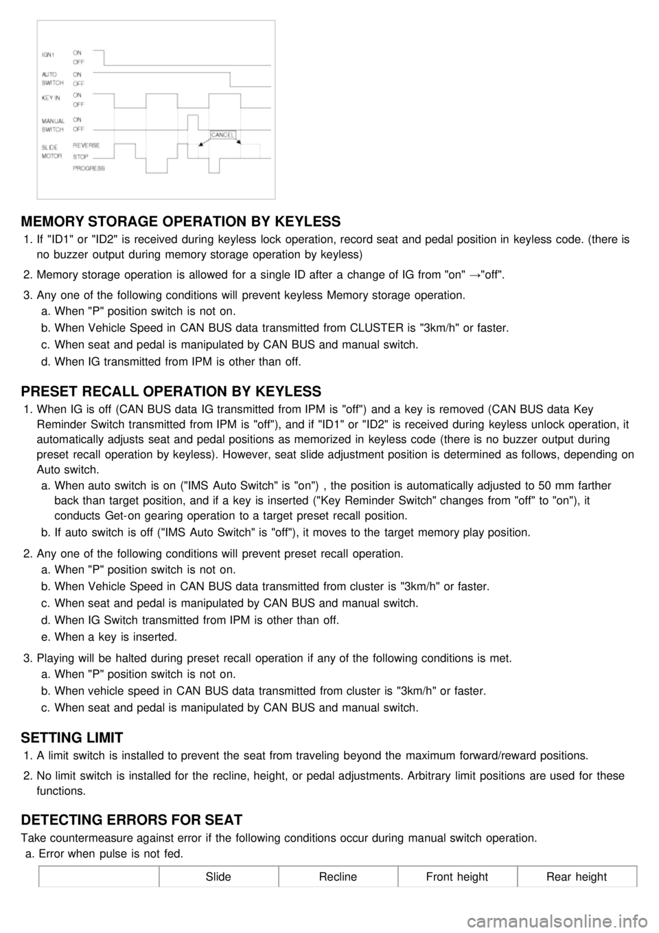
MEMORY STORAGE OPERATION BY KEYLESS
1.If "ID1" or "ID2" is received during keyless lock operation, record seat and pedal position in keyless code. (there is
no buzzer output during memory storage operation by keyless)
2. Memory storage operation is allowed for a single ID after a change of IG from "on" →"off".
3. Any one of the following conditions will prevent keyless Memory storage operation.
a. When "P" position switch is not on.
b. When Vehicle Speed in CAN BUS data transmitted from CLUSTER is "3km/h" or faster.
c. When seat and pedal is manipulated by CAN BUS and manual switch.
d. When IG transmitted from IPM is other than off.
PRESET RECALL OPERATION BY KEYLESS
1.When IG is off (CAN BUS data IG transmitted from IPM is "off") and a key is removed (CAN BUS data Key
Reminder Switch transmitted from IPM is "off"), and if "ID1" or "ID2" is received during keyless unlock operation, it
automatically adjusts seat and pedal positions as memorized in keyless code (there is no buzzer output during
preset recall operation by keyless). However, seat slide adjustment position is determined as follows, depending on
Auto switch.
a. When auto switch is on ("IMS Auto Switch" is "on") , the position is automatically adjusted to 50 mm farther
back than target position, and if a key is inserted ("Key Reminder Switch" changes from "off" to "on"), it
conducts Get- on gearing operation to a target preset recall position.
b. If auto switch is off ("IMS Auto Switch" is "off"), it moves to the target memory play position.
2. Any one of the following conditions will prevent preset recall operation.
a. When "P" position switch is not on.
b. When Vehicle Speed in CAN BUS data transmitted from cluster is "3km/h" or faster.
c. When seat and pedal is manipulated by CAN BUS and manual switch.
d. When IG Switch transmitted from IPM is other than off.
e. When a key is inserted.
3. Playing will be halted during preset recall operation if any of the following conditions is met.
a. When "P" position switch is not on.
b. When vehicle speed in CAN BUS data transmitted from cluster is "3km/h" or faster.
c. When seat and pedal is manipulated by CAN BUS and manual switch.
SETTING LIMIT
1.A limit switch is installed to prevent the seat from traveling beyond the maximum forward/reward positions.
2. No limit switch is installed for the recline, height, or pedal adjustments. Arbitrary limit positions are used for these
functions.
DETECTING ERRORS FOR SEAT
Take countermeasure against error if the following conditions occur during manual switch operation.
a. Error when pulse is not fed.
SlideReclineFront height Rear height
Page 1573 of 1575

2007 > 2.7L V6 GASOLINE >
ADJUSTMENT PROCEDURE
IGNITION LOCK SWITCH
1. Disconnect 2P- connector from a ignition lock switch.
2. Disconnect the ignition lock switch. (if you can install a tester with the switch fixed, this step can be omissible)
3. Check for continuity between terminals. (refer to the table below)
Clutch pedal position Ignition lock switch Continuity
Released ReleasedNO
Pressed PressedYES
If there is difference between what tested and the table above, replace the ignition lock switch with a new one.
If not, install the ignition lock switch and adjust the clutch pedal.
TORQUE :
8~10Nm (80~100kgf.cm, 5.8~7.2lb- ft)
Clutch pedal and Ignition lock switch
a. Inspect a ignition lock switch.
b. Remove the driver's seat mat to adjust a clutch pedal.
c. No gap between a clutch master cylinder pistion and push rod can cause clutch slip.
1. Loosen and draw out the bolt until it is off the pedal surface.
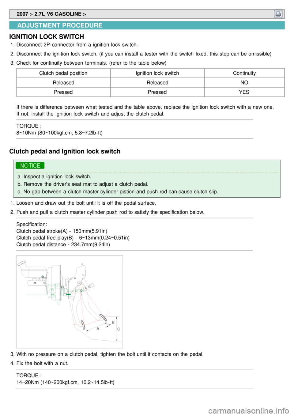
2. Push and pull a clutch master cylinder push rod to satisfy the specification below.
Specification:
Clutch pedal stroke(A) - 150mm(5.91in)
Clutch pedal free play(B) - 6~13mm(0.24~0.51in)
Clutch pedal distance - 234.7mm(9.24in)
3.With no pressure on a clutch pedal, tighten the bolt until it contacts on the pedal.
4. Fix the bolt with a nut.
TORQUE :
14~20Nm (140~200kgf.cm, 10.2~14.5lb - ft)