Page 1199 of 1575
Keyless Entry And
Burglar Alarm
Page 1200 of 1575
2007 > 2.7L V6 GASOLINE >
DESCRIPTION
KEYLESS ENTRY SYSTEM
The keyless entry system uses a handheld transmitter and IPM - mounted receiver to control door locks, alarm
functions, Power Tail Gate (PTG) and Power Sliding Doors (PSD).
The receiver of the keyless entry system are built- in the IPM(In - Panel Module).
Page 1207 of 1575
2007 > 2.7L V6 GASOLINE >
SPECIFICATION
Items Specifications
Keyless entry transmitter
Power source Lithium 3V battery (1EA)
Transmissible distance 30m or more
Life of battery 2 years or more (at 10 times per day)
Button Door lock/unlock
PSD(Power Sliding Door) open/close (option)
PTG(Power Tail Gate) open/close (option)
Panic
Tailgate open (option)
Transmission frequency 447 MHz (EUROPE, AUSTRAILIA, MIDDLE EAST)
315.00 MHZ (GENERAL)
Page 1211 of 1575

2007 > 2.7L V6 GASOLINE >
DESCRIPTION
All modules are linked a low speed CAN network.
The input information for the modules is coming from both the CAN network and the hardware components
(actuatorsand sensors).
a. FAM (Front Area Module)
a. Headlamp low/high beam control (with DRL)
b. Park lamp control
c. Front fog lamp control
d. Front turn signal lamp control
e. Windshield wiper control
f. Windshield deicer
g. Diagnostics
b. IPM (In - Panel Module)
a. RKE (Remote Keyless Control)
b. VAS (Voice Alarm System)
c. Ignition key hole illumination
d. Switch indicators control
e. Panel light control
f. Seat belt warning
g. Auto light/DRL control (Logic)
h. Windshield/Rear wiper control (Logic)
i. Turn and Hazard lamp control (Logic)
j. Central door lock (Logic)
k. Windshield deicer timer
l. Rear glass defog timer
m. Gateway for ISO- 9141 (K- Line)
c. RAM (Rear Area Module)
a. Tail lamp control
b. Turn and Hazard lamp control
c. Back up lamp control
d. Rea fog lamp control
e. Stop lamp outage detection
f. Sliding door power window/Quarter glass control
g. Room lamp control
h. Rear wiper control
i. Rear glass defog
j. Fuel filler door open solenoid control
d. ADM (Assist Drive Module)
e. DDM (Driver Drive Module)
MODULE INTRODUCTION
FAM/IPM/RAM consists of a power board and an electronic board. The power board contains circuit protection devices
and switching devices. The electronic board uses Intelligent Power Switching (IPS) for HS/LS load control, logic
functions and CAN/K- Line communication. The power board and electronic board are connected with pin blocks for
the Front Area Module (FAM) and VCD (Variable Connection Displacement) for the In- Panel Module (IPM) and the
Rear Area Module (RAM).
Page 1214 of 1575

Turn Signal And Side Repeater Lamps Function
1.Necessary conditions to switch ON(if they are standard) :
a. By activation of Crash Unlock
b. During the opening / closing of the Tail gate by the PTG Flasher input
c. With the Remote Keyless Entry to lock / unlock the vehicle
d. By alarm activation
e. By panic activation with the Remote Keyless Entry
f. By activation of the Hazard Lamp by the hazard switch and ignition is position OFF, ACC or RUN
g. By using the turn lever switch with the ignition switch in the ON position.
2. Necessary conditions to switch OFF(if they are standard) :
a. Ignition switch in OFF position for deactivation of crash unlock flashing
b. Deactivation of the alarm or at the end of the alarm flashing sequence
c. Deactivation of panic sequence with pushing any button of the Remote Keyless Entry or at the end of the panic
flashing sequence
d. Turn lever switch command in OFF postion or ignition switch in OFF, ACC or START position to stop turn lever
flashing.
e. The hazard switch in OFF position or ignition switch in position START to stop the Hazard flashing.
f. At the end of the Lock, Unlock and PTG flashing sequence.
3. During the start up of the vehicle (ignition key in position START) :
a. The Turn signal lamps activated by the turn lever switch are temporarily turned OFF. If the time duration in Start
position is more than 10seconds and engine running, the Turn signal lamps are managed again as if the ignition
key was in ON position,
b. The flashing sequence of the hazard lamps is immediately stopped if they have been activated by the hazard
button. If the time duration in Start position is more than 10seconds and engine running, the flashing sequence
of the hazard lamps are managed again as if the ignition key was in RUN position,
c. The flashing sequence of the hazard lamps is not stopped if they have been activated by a crash unlock.
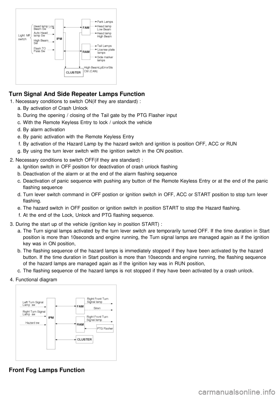
4. Functional diagram
Front Fog Lamps Function
Page 1230 of 1575

g.7th : Light ON warning
h. 8th : Key learning sound
3. If two different warning condition happen at the same time, chime should work only for the highest warning
condition.
4. Cluster indicators should work for two warning behavior.
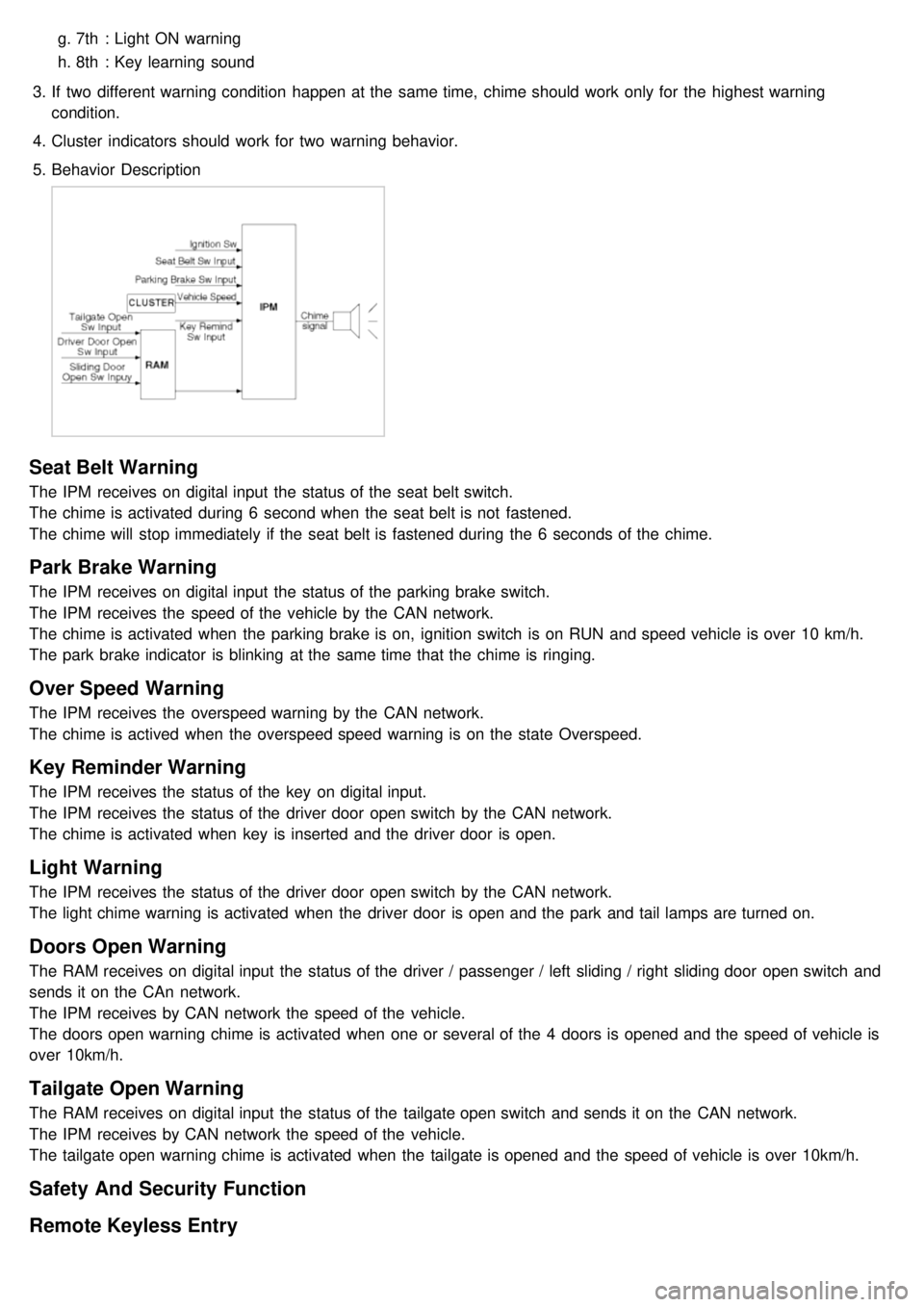
5. Behavior Description
Seat Belt Warning
The IPM receives on digital input the status of the seat belt switch.
The chime is activated during 6 second when the seat belt is not fastened.
The chime will stop immediately if the seat belt is fastened during the 6 seconds of the chime.
Park Brake Warning
The IPM receives on digital input the status of the parking brake switch.
The IPM receives the speed of the vehicle by the CAN network.
The chime is activated when the parking brake is on, ignition switch is on RUN and speed vehicle is over 10 km/h.
The park brake indicator is blinking at the same time that the chime is ringing.
Over Speed Warning
The IPM receives the overspeed warning by the CAN network.
The chime is actived when the overspeed speed warning is on the state Overspeed.
Key Reminder Warning
The IPM receives the status of the key on digital input.
The IPM receives the status of the driver door open switch by the CAN network.
The chime is activated when key is inserted and the driver door is open.
Light Warning
The IPM receives the status of the driver door open switch by the CAN network.
The light chime warning is activated when the driver door is open and the park and tail lamps are turned on.
Doors Open Warning
The RAM receives on digital input the status of the driver / passenger / left sliding / right sliding door open switch and
sends it on the CAn network.
The IPM receives by CAN network the speed of the vehicle.
The doors open warning chime is activated when one or several of the 4 doors is opened and the speed of vehicle is
over 10km/h.
Tailgate Open Warning
The RAM receives on digital input the status of the tailgate open switch and sends it on the CAN network.
The IPM receives by CAN network the speed of the vehicle.
The tailgate open warning chime is activated when the tailgate is opened and the speed of vehicle is over 10km/h.
Safety And Security Function
Remote Keyless Entry
Page 1232 of 1575
Key Reminder Unlock
1.Key reminder door unlock does not take into account the lock/unlock commands from RKE, key cylinder or door
lock switches. It only takes into account the state of the door lock monitoring switch, key reminder switch and door
open status in order to proceed with the unlock sequence or not.
2. Functional Diagram
Remote Keyless Entry Panic
1.Working Conditions
RKE panic function is only active when the key is out of key cylinder.
Once started, panic operation is not stopped when ignition key is inserted, ignition is ACC, RUN or START, or
door is opened or closed.
2. Functional Diagram
Page 1251 of 1575
No.Description ValueControl
1 Power Seat Slide Forward Motor ON/OFFContinuously ON
2 Power Seat Slide Backward Motor ON/OFFContinuously ON
3 Power Seat FR Height Up Motor ON/OFFContinuously ON
4 Power Seat FR Height Down Motor ON/OFFContinuously ON
5 Power Seat RR Height Up Motor ON/OFFContinuously ON
6 Power Seat RR Height Down Motor ON/OFFContinuously ON
7 Power Seat Recline Forward Motor ON/OFFContinuously ON
8 Power Seat Recline Backward Motor ON/OFFContinuously ON
9 Pedal Forward Motor ON/OFFContinuously ON
10 Pedal Backward Motor ON/OFFContinuously ON
REPLACEMENT
IPM (In-Panel Module)
1. Disconnect the negative ( - ) battery terminal.
2. Remove the crash pad lower panel (A).
(Refer to the Body group - crash pad)
[LHD]
[RHD]
3.Remove the keyless antenna cable and IPM(Instrument Panel Module)(A) after loosening 3 nuts and disconnecting
5 connectors.