2007 KIA CARNIVAL fuse
[x] Cancel search: fusePage 1245 of 1575
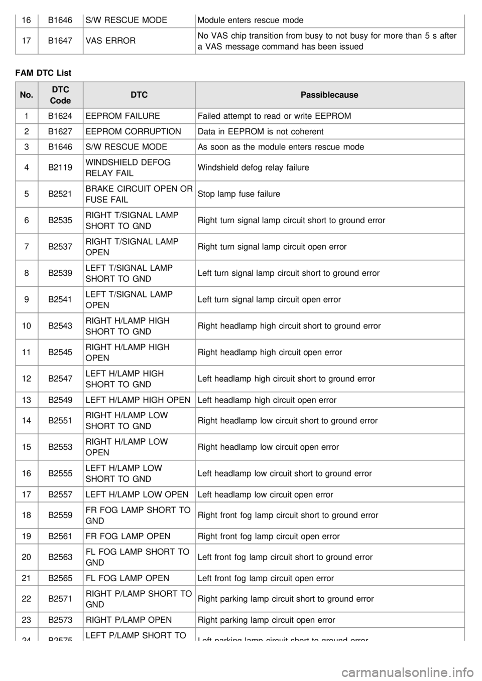
16B1646 S/W RESCUE MODE Module enters rescue mode
17 B1647 VAS ERROR No VAS chip transition from busy to not busy for more than 5 s after
a VAS message command has been issued
FAM DTC List No. DTC
Code DTC
Passiblecause
1 B1624 EEPROM FAILURE Failed attempt to read or write EEPROM
2 B1627 EEPROM CORRUPTION Data in EEPROM is not coherent
3 B1646 S/W RESCUE MODE As soon as the module enters rescue mode
4 B2119 WINDSHIELD DEFOG
RELAY FAIL Windshield defog relay failure
5 B2521 BRAKE CIRCUIT OPEN OR
FUSE FAIL Stop lamp fuse failure
6 B2535 RIGHT T/SIGNAL LAMP
SHORT TO GND Right turn signal lamp circuit short to ground error
7 B2537 RIGHT T/SIGNAL LAMP
OPEN Right turn signal lamp circuit open error
8 B2539 LEFT T/SIGNAL LAMP
SHORT TO GND Left turn signal lamp circuit short to ground error
9 B2541 LEFT T/SIGNAL LAMP
OPEN Left turn signal lamp circuit open error
10 B2543 RIGHT H/LAMP HIGH
SHORT TO GND Right headlamp high circuit short to ground error
11 B2545 RIGHT H/LAMP HIGH
OPEN Right headlamp high circuit open error
12 B2547 LEFT H/LAMP HIGH
SHORT TO GND Left headlamp high circuit short to ground error
13 B2549 LEFT H/LAMP HIGH OPEN Left headlamp high circuit open error
14 B2551 RIGHT H/LAMP LOW
SHORT TO GND Right headlamp low circuit short to ground error
15 B2553 RIGHT H/LAMP LOW
OPEN Right headlamp low circuit open error
16 B2555 LEFT H/LAMP LOW
SHORT TO GND Left headlamp low circuit short to ground error
17 B2557 LEFT H/LAMP LOW OPEN Left headlamp low circuit open error
18 B2559 FR FOG LAMP SHORT TO
GND Right front fog lamp circuit short to ground error
19 B2561 FR FOG LAMP OPEN Right front fog lamp circuit open error
20 B2563 FL FOG LAMP SHORT TO
GND Left front fog lamp circuit short to ground error
21 B2565 FL FOG LAMP OPEN Left front fog lamp circuit open error
22 B2571 RIGHT P/LAMP SHORT TO
GND Right parking lamp circuit short to ground error
23 B2573 RIGHT P/LAMP OPEN Right parking lamp circuit open error
24 B2575 LEFT P/LAMP SHORT TO
GND Left parking lamp circuit short to ground error
Page 1259 of 1575
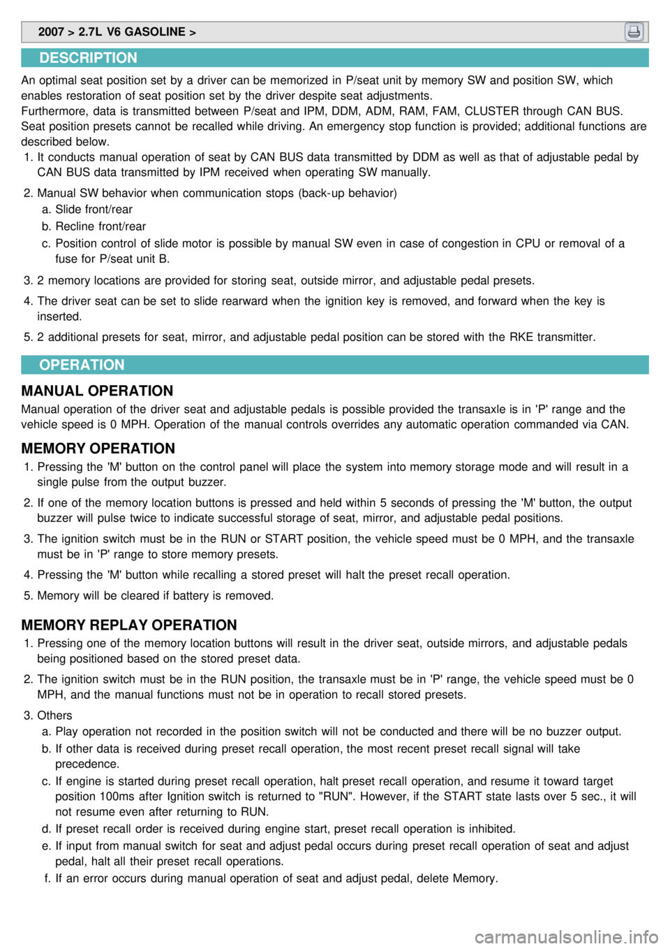
2007 > 2.7L V6 GASOLINE >
DESCRIPTION
An optimal seat position set by a driver can be memorized in P/seat unit by memory SW and position SW, which
enables restoration of seat position set by the driver despite seat adjustments.
Furthermore, data is transmitted between P/seat and IPM, DDM, ADM, RAM, FAM, CLUSTER through CAN BUS.
Seat position presets cannot be recalled while driving. An emergency stop function is provided; additional functions are
described below.
1. It conducts manual operation of seat by CAN BUS data transmitted by DDM as well as that of adjustable pedal by
CAN BUS data transmitted by IPM received when operating SW manually.
2. Manual SW behavior when communication stops (back- up behavior)
a. Slide front/rear
b. Recline front/rear
c. Position control of slide motor is possible by manual SW even in case of congestion in CPU or removal of a
fuse for P/seat unit B.
3. 2 memory locations are provided for storing seat, outside mirror, and adjustable pedal presets.
4. The driver seat can be set to slide rearward when the ignition key is removed, and forward when the key is
inserted.
5. 2 additional presets for seat, mirror, and adjustable pedal position can be stored with the RKE transmitter.
OPERATION
MANUAL OPERATION
Manual operation of the driver seat and adjustable pedals is possible provided the transaxle is in 'P' range and the
vehicle speed is 0 MPH. Operation of the manual controls overrides any automatic operation commanded via CAN.
MEMORY OPERATION
1. Pressing the 'M' button on the control panel will place the system into memory storage mode and will result in a
single pulse from the output buzzer.
2. If one of the memory location buttons is pressed and held within 5 seconds of pressing the 'M' button, the output
buzzer will pulse twice to indicate successful storage of seat, mirror, and adjustable pedal positions.
3. The ignition switch must be in the RUN or START position, the vehicle speed must be 0 MPH, and the transaxle
must be in 'P' range to store memory presets.
4. Pressing the 'M' button while recalling a stored preset will halt the preset recall operation.
5. Memory will be cleared if battery is removed.
MEMORY REPLAY OPERATION
1.Pressing one of the memory location buttons will result in the driver seat, outside mirrors, and adjustable pedals
being positioned based on the stored preset data.
2. The ignition switch must be in the RUN position, the transaxle must be in 'P' range, the vehicle speed must be 0
MPH, and the manual functions must not be in operation to recall stored presets.
3. Others
a. Play operation not recorded in the position switch will not be conducted and there will be no buzzer output.
b. If other data is received during preset recall operation, the most recent preset recall signal will take
precedence.
c. If engine is started during preset recall operation, halt preset recall operation, and resume it toward target
position 100ms after Ignition switch is returned to "RUN". However, if the START state lasts over 5 sec., it will
not resume even after returning to RUN.
d. If preset recall order is received during engine start, preset recall operation is inhibited.
e. If input from manual switch for seat and adjust pedal occurs during preset recall operation of seat and adjust
pedal, halt all their preset recall operations.
f. If an error occurs during manual operation of seat and adjust pedal, delete Memory.
Page 1285 of 1575

Fuses and Relays
Page 1290 of 1575
2007 > 2.7L V6 GASOLINE >
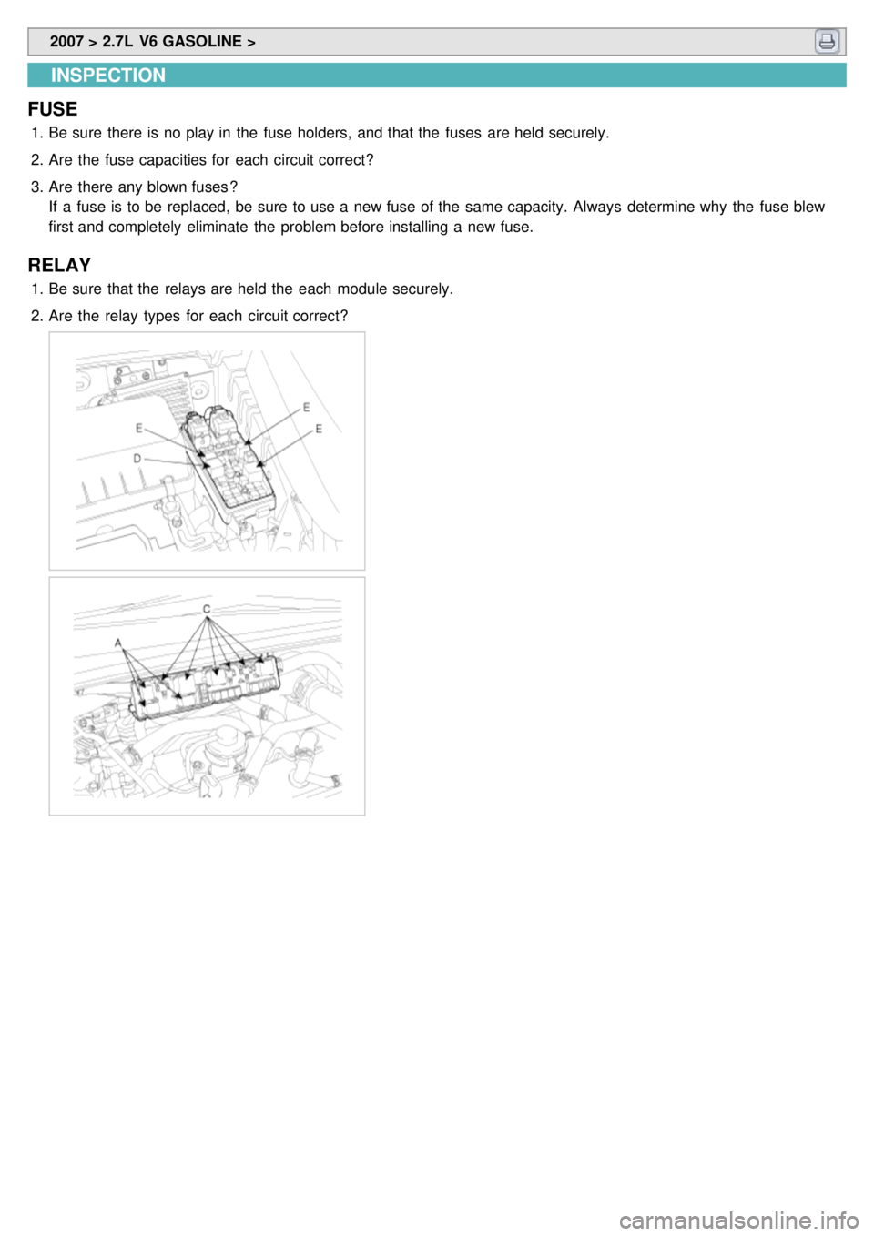
INSPECTION
FUSE
1. Be sure there is no play in the fuse holders, and that the fuses are held securely.
2. Are the fuse capacities for each circuit correct?
3. Are there any blown fuses ?
If a fuse is to be replaced, be sure to use a new fuse of the same capacity. Always determine why the fuse blew
first and completely eliminate the problem before installing a new fuse.
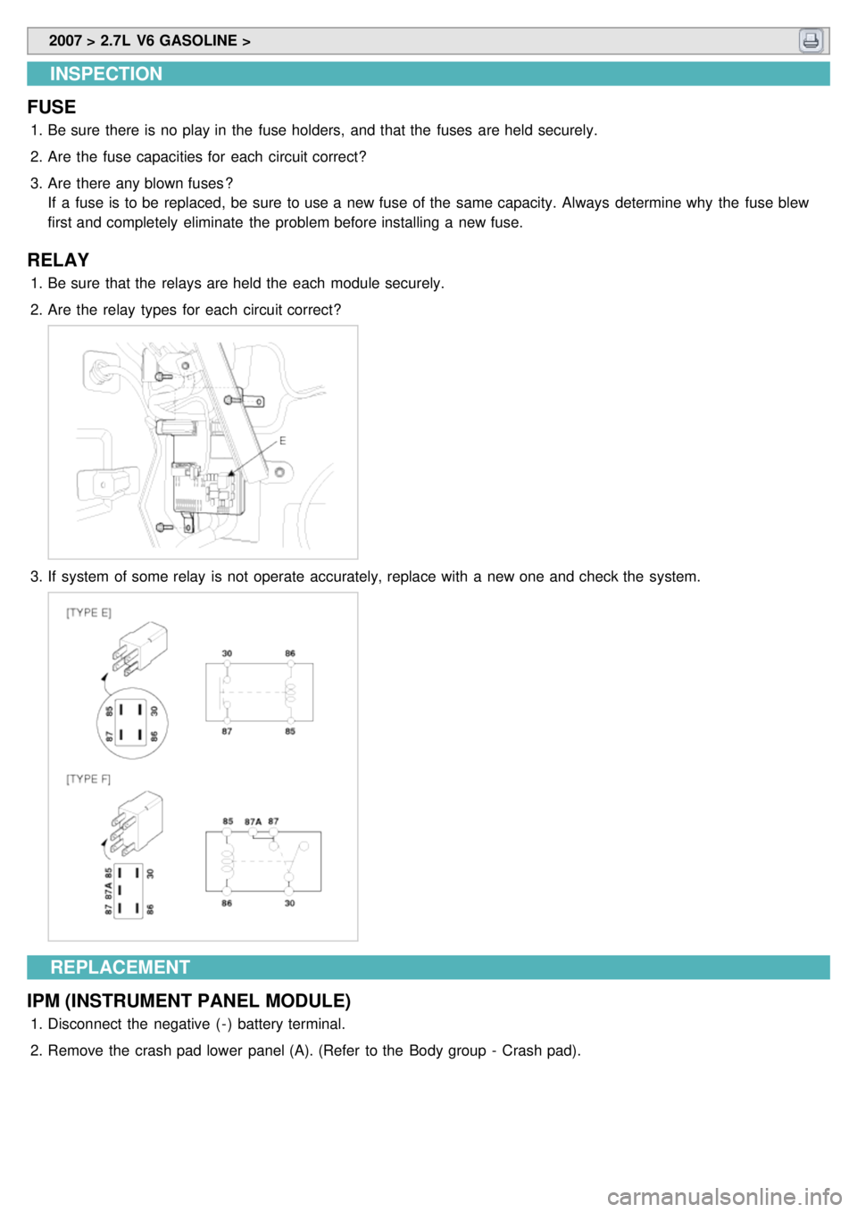
RELAY
1.Be sure that the relays are held the each module securely.
2. Are the relay types for each circuit correct?
Page 1298 of 1575
2007 > 2.7L V6 GASOLINE >
INSPECTION
FUSE
1. Be sure there is no play in the fuse holders, and that the fuses are held securely.
2. Are the fuse capacities for each circuit correct?
3. Are there any blown fuses ?
If a fuse is to be replaced, be sure to use a new fuse of the same capacity. Always determine why the fuse blew
first and completely eliminate the problem before installing a new fuse.
RELAY
1.Be sure that the relays are held the each module securely.
2. Are the relay types for each circuit correct?
3.If system of some relay is not operate accurately, replace with a new one and check the system.
REPLACEMENT
IPM (INSTRUMENT PANEL MODULE)
1. Disconnect the negative ( - ) battery terminal.
2. Remove the crash pad lower panel (A). (Refer to the Body group - Crash pad).
Page 1331 of 1575
2007 > 2.7L V6 GASOLINE >
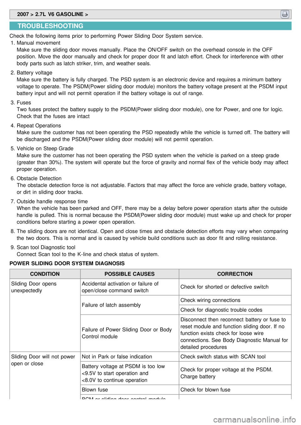
TROUBLESHOOTING
Check the following items prior to performing Power Sliding Door System service.
1. Manual movement
Make sure the sliding door moves manually. Place the ON/OFF switch on the overhead console in the OFF
position. Move the door manually and check for proper door fit and latch effort. Check for interference with other
body parts such as latch striker, trim, and weather seals.
2. Battery voltage
Make sure the battery is fully charged. The PSD system is an electronic device and requires a minimum battery
voltage to operate. The PSDM(Power sliding door module) monitors the battery voltage present at the PSDM input
battery input and will not permit operation if the battery voltage is out of range.
3. Fuses
Two fuses protect the battery supply to the PSDM(Power sliding door module), one for Power, and one for logic.
Check that the fuses are intact
4. Repeat Operations
Make sure the customer has not been operating the PSD repeatedly while the vehicle is turned off. The battery will
be discharged and the PSDM(Power sliding door module) will not permit operation.
5. Vehicle on Steep Grade
Make sure the customer has not been operating the PSD system when the vehicle is parked on a steep grade
(greater than 30%). The system will operate but the force of gravity and normal flex of the vehicle body may affect
proper operation.
6. Obstacle Detection
The obstacle detection force is not adjustable. Factors that may affect the force are vehicle grade, battery voltage,
or dirt in sliding door tracks.
7. Outside handle response time
When the vehicle has been parked and OFF, there may be a delay before power operation starts after the outside
handle is pulled. This is normal because the PSDM(Power sliding door module) must wake up and check for proper
conditions before starting a power open operation.
8. The sliding doors are not identical. Open and close times and obstacle detection efforts may vary when comparing
the two doors. This is normal and is caused by vehicle build conditions such as door fit and rolling resistance.
9. Scan tool Diagnostic tool
Connect Scan tool to the K- line and check status of system.
POWER SLIDING DOOR SYSTEM DIAGNOSIS
CONDITION POSSIBLE CAUSES CORRECTION
Sliding Door opens
unexpectedly Accidental activation or failure of
open/close command switch
Check for shorted or defective switch
Failure of latch assembly Check wiring connections
Check for diagnostic trouble codes
Failure of Power Sliding Door or Body
Control module Disconnect then reconnect battery or fuse to
reset module and function sliding door. If no
function exists check for loose wire
connections. See Body Diagnostic Manual for
detailed procedures
Sliding Door will not power
open or close Not in Park or false indication
Check switch status with SCAN tool
Battery voltage at PSDM is too low
<9.5V to start operation and
<8.0V to continue operation Check for proper voltage at the PSDM.
Charge battery
Blown fuse Check for blown fuse
BCM or sliding door control module
Page 1332 of 1575
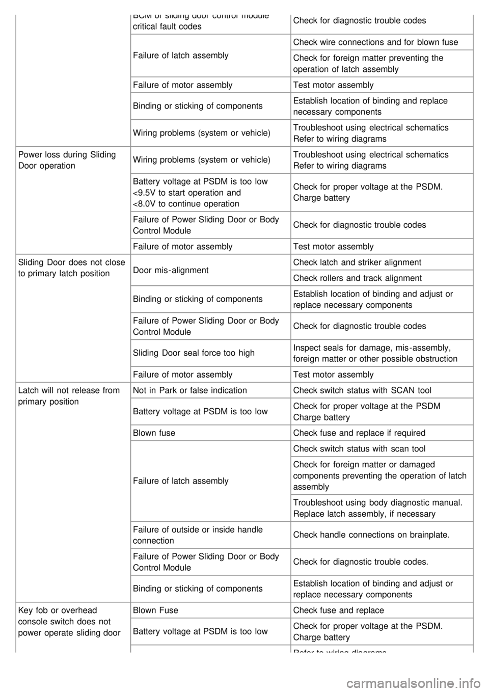
BCM or sliding door control module
critical fault codesCheck for diagnostic trouble codes
Failure of latch assembly Check wire connections and for blown fuse
Check for foreign matter preventing the
operation of latch assembly
Failure of motor assembly Test motor assembly
Binding or sticking of components Establish location of binding and replace
necessary components
Wiring problems (system or vehicle) Troubleshoot using electrical schematics
Refer to wiring diagrams
Power loss during Sliding
Door operation Wiring problems (system or vehicle)
Troubleshoot using electrical schematics
Refer to wiring diagrams
Battery voltage at PSDM is too low
<9.5V to start operation and
<8.0V to continue operation Check for proper voltage at the PSDM.
Charge battery
Failure of Power Sliding Door or Body
Control Module Check for diagnostic trouble codes
Failure of motor assembly Test motor assembly
Sliding Door does not close
to primary latch position Door mis - alignment Check latch and striker alignment
Check rollers and track alignment
Binding or sticking of components Establish location of binding and adjust or
replace necessary components
Failure of Power Sliding Door or Body
Control Module Check for diagnostic trouble codes
Sliding Door seal force too high Inspect seals for damage, mis - assembly,
foreign matter or other possible obstruction
Failure of motor assembly Test motor assembly
Latch will not release from
primary position Not in Park or false indication
Check switch status with SCAN tool
Battery voltage at PSDM is too low Check for proper voltage at the PSDM
Charge battery
Blown fuse Check fuse and replace if required
Failure of latch assembly Check switch status with scan tool
Check for foreign matter or damaged
components preventing the operation of latch
assembly
Troubleshoot using body diagnostic manual.
Replace latch assembly, if necessary
Failure of outside or inside handle
connection Check handle connections on brainplate.
Failure of Power Sliding Door or Body
Control Module Check for diagnostic trouble codes.
Binding or sticking of components Establish location of binding and adjust or
replace necessary components
Key fob or overhead
console switch does not
power operate sliding door Blown Fuse
Check fuse and replace
Battery voltage at PSDM is too low Check for proper voltage at the PSDM.
Charge battery
Refer to wiring diagrams
Page 1336 of 1575
2007 > 2.7L V6 GASOLINE >
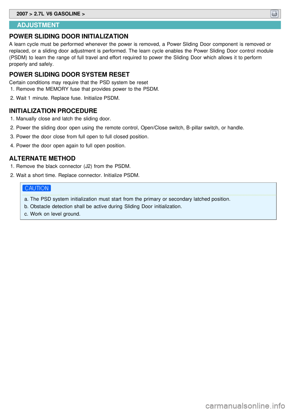
ADJUSTMENT
POWER SLIDING DOOR INITIALIZATION
A learn cycle must be performed whenever the power is removed, a Power Sliding Door component is removed or
replaced, or a sliding door adjustment is performed. The learn cycle enables the Power Sliding Door control module
(PSDM) to learn the range of full travel and effort required to power the Sliding Door which allows it to perform
properly and safely.
POWER SLIDING DOOR SYSTEM RESET
Certain conditions may require that the PSD system be reset 1. Remove the MEMORY fuse that provides power to the PSDM.
2. Wait 1 minute. Replace fuse. Initialize PSDM.
INITIALIZATION PROCEDURE
1.Manually close and latch the sliding door.
2. Power the sliding door open using the remote control, Open/Close switch, B- pillar switch, or handle.
3. Power the door close from full open to full closed position.
4. Power the door open again to full open position.
ALTERNATE METHOD
1.Remove the black connector (J2) from the PSDM.
2. Wait a short time. Replace connector. Initialize PSDM.
a.The PSD system initialization must start from the primary or secondary latched position.
b. Obstacle detection shall be active during Sliding Door initialization.
c. Work on level ground.