Page 993 of 1575

2007 > 2.7L V6 GASOLINE >
TROUBLESHOOTING
Symptom Suspect AreaRemedy (See page)
Water leaks from sunroof Dirt accumulated in drain tube Clear dirt inside of drain
Clogged drain tube Blow air into drain to remove dirt
Broken or dislocated drain tube, defective
Or cracked clip Check tube installation and
Flange contact
Deteriorated roof lid weatherstrip Replace
Excessive roof lid - to- body clearance and
Improperly fitted weatherstrip Adjust
Wind noise around sunroof Loose or deformed deflector, gaps
In body work Retighten adjust or replace
Sunroof lid makes a noise when
moveing Foreign particles lodged in guide rail
Check drive cable and guide
Rails for foreign particles
Loose guide rails and lid Retighten
Motor runs but sunroof does not
move or moves only partially Foreign particles lodged in guide rail
Check drive cable and guide
Rails for foreign particles
Incorrect engagement of motor pinion
With drive cable Check for loose motor installation
And damaged pinion
Decrease in motor`s clutch slipping force Adjust
Increased sunroof sliding resistance
Or interference of sunroof with drive
cables, weatherstrip, etc. due to
maladjustment of sunroof Adjust or replace
Noise in motor (clutch slipping
Noise from motor when sunroof
Is fully opened or closed is not
An unusual noise Incorrect engagement of motor pinion
With drive cable
Check pinion installation and
Retighten motor
Worn out or damaged motor pinion bearing Replace motor assembly
Worn out or deformed drive cable Replace
Door glass fails to operate
Up and down Incorrect window glass installation
Adjust position
Damaged or faulty regulator arm or regulator Correct or replace
Door does not open or close
completely Incorrect door installation
Adjust position
Defective door check assembly Correct or replace
Door hinge requires grease Apply grease
Hood does not open or close
completely Striker and latch not properly aligned
Adjust
Incorrectly installed hood Adjust
Incorrect hood bumper height Adjust
Water leak through windshield
end rear window Defective seal
Fill with sealant
Defective flange Correct
Page 994 of 1575

2007 > 2.7L V6 GASOLINE >
SPECIFICATIONS
HOOD Type Rear hinged, gas lifter type
REAR DOOR Construction
Regulator system
Locking system Front hinged, full door construction
X- ARM type
Pin- fork system
FRONT DOOR Construction
Regulator system
Locking system Sliding door construction
Wire drum type
Pin- fork system
TAILGATE Type Inner hinged, gas lifter type
GLASS
THICKNESS Windshield glass
Front door glass
Rear door glass
Rear window glass 5mm
4mm
4mm
3.5mm
SEAT BELTS Front
Rear 3 point type with Emergency Locking Retractor
(E.L.R)
3 point type with Emergency Locking Retractor
(E.L.R)
TIGHTENING TORQUE
Items
N.mKgf.m Lbf.ft
Front and rear doors Door hinge to body
Door hinge to door
Striker
Glass mounting bolt
Outside handle mounting bolt
Rear channel mounting nut 33.3~41.2
21.6~26.5
6.9~10.8
7.8~11.8
6.9~10.8
7.8~11.8 3.4~4.2
2.2~2.7
0.7~1.1
0.8~1.2
0.7~1.1
0.8~1.224.6~30.4
15.9~19.5
5.1~8.0
5.8~8.7
5.1~8.0
5.8~8.7
Tailgate Tailgate hinge to body
Tailgate hinge to tailgate
Tailgate lift mounting bolt
Key cylinder mounting nut 6.9~8.8
6.9~8.8
6.9~8.8
6.9~10.8 0.7~0.9
0.7~0.9
0.7~0.9
0.7~1.15.1~6.5
5.1~6.5
5.1~6.5
5.1~8.0
Hood Hood hinge to body
Hood hinge to hood
Hood latch to body 21.6~26.5
21.6~26.5
6.9~10.8 2.2~2.7
2.2~2.7
0.7~1.115.9~19.5
15.9~19.5
5.1~8.0
Seat Front seat mounting bolts
Rear seat mounting bolts 43.1~64.7
43.1~64.74.4~6.6
4.4~6.631.8~47.7
31.8~47.7
Seat belt Front seat belt height adjuster
Front seat belt buckle
mounting bolt
Front seat belt anchor
mounting bolt
Front seat belt lower anchor
Front seat belt upper anchor
Rear seat belt anchor
attaching bolt
Rear seat belt retractor
mounting bolt 39.2~53.9
39.2~53.9
39.2~53.9
39.2~53.9
39.2~53.9
39.2~53.9
39.2~53.9
4.0~5.5
4.0~5.5
4.0~5.5
4.0~5.5
4.0~5.5
4.0~5.5
4.0~5.528.9~39.8
28.9~39.8
28.9~39.8
28.9~39.8
28.9~39.8
28.9~39.8
28.9~39.8
Page 1170 of 1575

2007 > 2.7L V6 GASOLINE >
SPECIFICATION
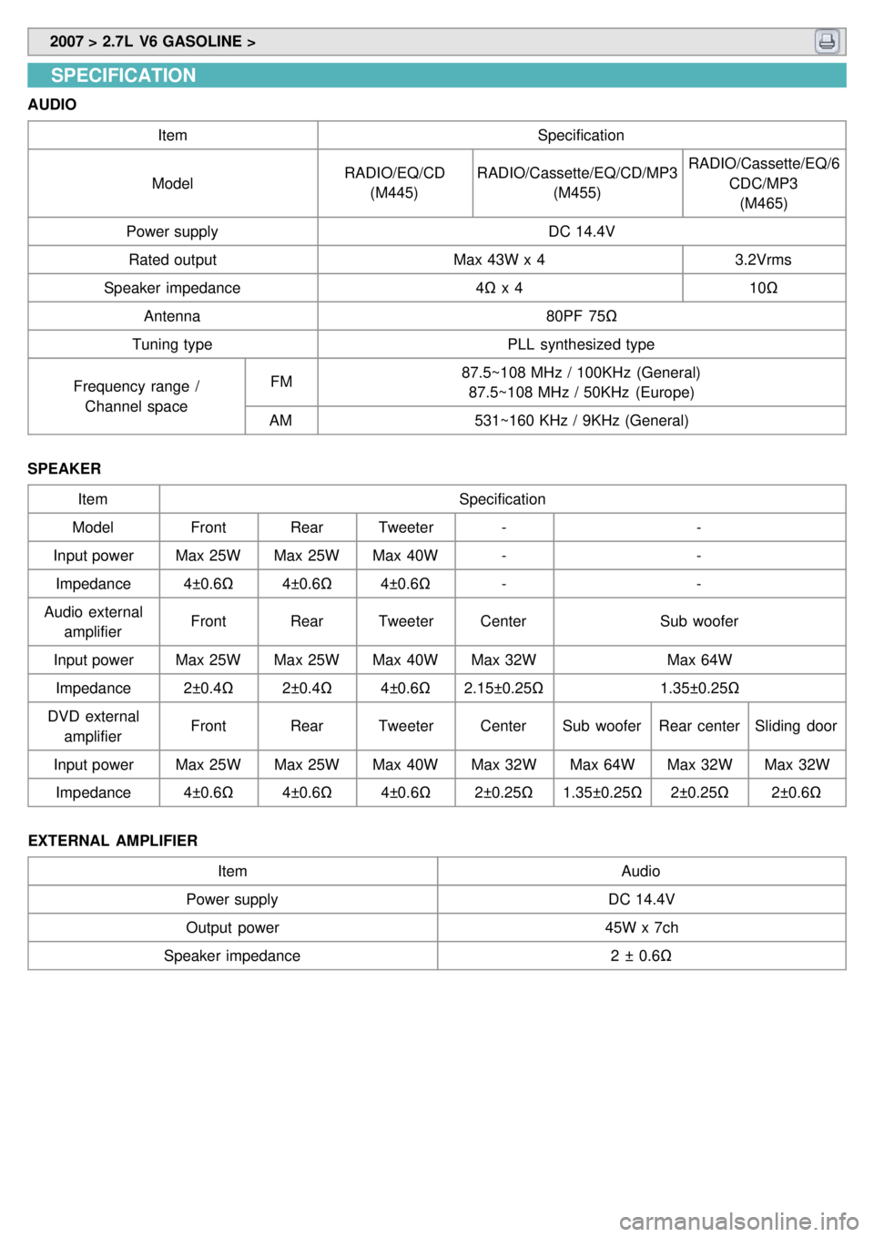
AUDIO
Item Specification
Model RADIO/EQ/CD
(M445) RADIO/Cassette/EQ/CD/MP3
(M455) RADIO/Cassette/EQ/6
CDC/MP3(M465)
Power supply DC 14.4V
Rated output Max 43W x 43.2Vrms
Speaker impedance 4Ω x 4 10Ω
Antenna 80PF 75Ω
Tuning type PLL synthesized type
Frequency range / Channel space FM
87.5~108 MHz / 100KHz (General)
87.5~108 MHz / 50KHz (Europe)
AM 531~160 KHz / 9KHz (General)
SPEAKER Item Specification
Model FrontRearTweeter - -
Input power Max 25WMax 25WMax 40W - -
Impedance 4±0.6Ω4±0.6Ω4±0.6Ω - -
Audio external amplifier Front
RearTweeter Center Sub woofer
Input power Max 25WMax 25WMax 40WMax 32W Max 64W
Impedance 2±0.4Ω2±0.4Ω4±0.6Ω2.15±0.25Ω 1.35±0.25Ω
DVD external amplifier Front
RearTweeter CenterSub woofer Rear centerSliding door
Input power Max 25WMax 25WMax 40WMax 32WMax 64WMax 32WMax 32W
Impedance 4±0.6Ω4±0.6Ω4±0.6Ω2±0.25Ω1.35±0.25Ω 2±0.25Ω2±0.6Ω
EXTERNAL AMPLIFIER Item Audio
Power supply DC 14.4V
Output power 45W x 7ch
Speaker impedance 2 ± 0.6Ω
Page 1200 of 1575
2007 > 2.7L V6 GASOLINE >
DESCRIPTION
KEYLESS ENTRY SYSTEM
The keyless entry system uses a handheld transmitter and IPM - mounted receiver to control door locks, alarm
functions, Power Tail Gate (PTG) and Power Sliding Doors (PSD).
The receiver of the keyless entry system are built- in the IPM(In - Panel Module).
Page 1202 of 1575
2007 > 2.7L V6 GASOLINE >
INSPECTION
FRONT DOOR LOCK ACTUATOR
1. Remove the front door trim panel. (Refer to the Body group - front door)
2. Disconnect the 4P connector from the actuator.
3.Check actuator operation by connecting power and ground according to the table. To prevent damage to the
actuator, apply battery voltage only momentarily.
SLIDING DOOR LOCK ACTUATOR
1.Remove the sliding door trim panel. (Refer to the Body group - rear door)
2. Disconnect the 6P connector from the actuator.
3.Check actuator operation by connecting power and ground according to the table. To prevent damage to the
actuator, apply battery voltage only momentarily.
Page 1204 of 1575
SLIDING DOOR LOCK SWITCH
1.Remove the sliding door trim panel. (Refer to the Body group - rear door)
2. Disconnect the 6P connector from the actuator.
3.Check for continuity between the terminals in each switch position according to the table.
TAILGATE LOCK SWITCH
1.Remove the tailgate trim panel. (Refer to the Body group - tailgate)
2. Disconnect the 6P connector from the actuator.
3.Check for continuity between the terminals in each switch position according to the table.
Page 1207 of 1575
2007 > 2.7L V6 GASOLINE >
SPECIFICATION
Items Specifications
Keyless entry transmitter
Power source Lithium 3V battery (1EA)
Transmissible distance 30m or more
Life of battery 2 years or more (at 10 times per day)
Button Door lock/unlock
PSD(Power Sliding Door) open/close (option)
PTG(Power Tail Gate) open/close (option)
Panic
Tailgate open (option)
Transmission frequency 447 MHz (EUROPE, AUSTRAILIA, MIDDLE EAST)
315.00 MHZ (GENERAL)
Page 1211 of 1575

2007 > 2.7L V6 GASOLINE >
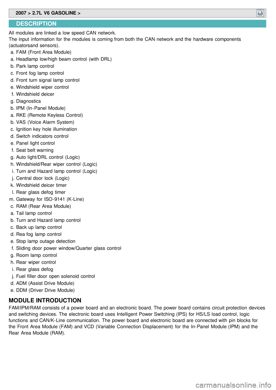
DESCRIPTION
All modules are linked a low speed CAN network.
The input information for the modules is coming from both the CAN network and the hardware components
(actuatorsand sensors).
a. FAM (Front Area Module)
a. Headlamp low/high beam control (with DRL)
b. Park lamp control
c. Front fog lamp control
d. Front turn signal lamp control
e. Windshield wiper control
f. Windshield deicer
g. Diagnostics
b. IPM (In - Panel Module)
a. RKE (Remote Keyless Control)
b. VAS (Voice Alarm System)
c. Ignition key hole illumination
d. Switch indicators control
e. Panel light control
f. Seat belt warning
g. Auto light/DRL control (Logic)
h. Windshield/Rear wiper control (Logic)
i. Turn and Hazard lamp control (Logic)
j. Central door lock (Logic)
k. Windshield deicer timer
l. Rear glass defog timer
m. Gateway for ISO- 9141 (K- Line)
c. RAM (Rear Area Module)
a. Tail lamp control
b. Turn and Hazard lamp control
c. Back up lamp control
d. Rea fog lamp control
e. Stop lamp outage detection
f. Sliding door power window/Quarter glass control
g. Room lamp control
h. Rear wiper control
i. Rear glass defog
j. Fuel filler door open solenoid control
d. ADM (Assist Drive Module)
e. DDM (Driver Drive Module)
MODULE INTRODUCTION
FAM/IPM/RAM consists of a power board and an electronic board. The power board contains circuit protection devices
and switching devices. The electronic board uses Intelligent Power Switching (IPS) for HS/LS load control, logic
functions and CAN/K- Line communication. The power board and electronic board are connected with pin blocks for
the Front Area Module (FAM) and VCD (Variable Connection Displacement) for the In- Panel Module (IPM) and the
Rear Area Module (RAM).