2007 KIA CARNIVAL sliding door
[x] Cancel search: sliding doorPage 1225 of 1575
Adjustable Pedal(non-ims)
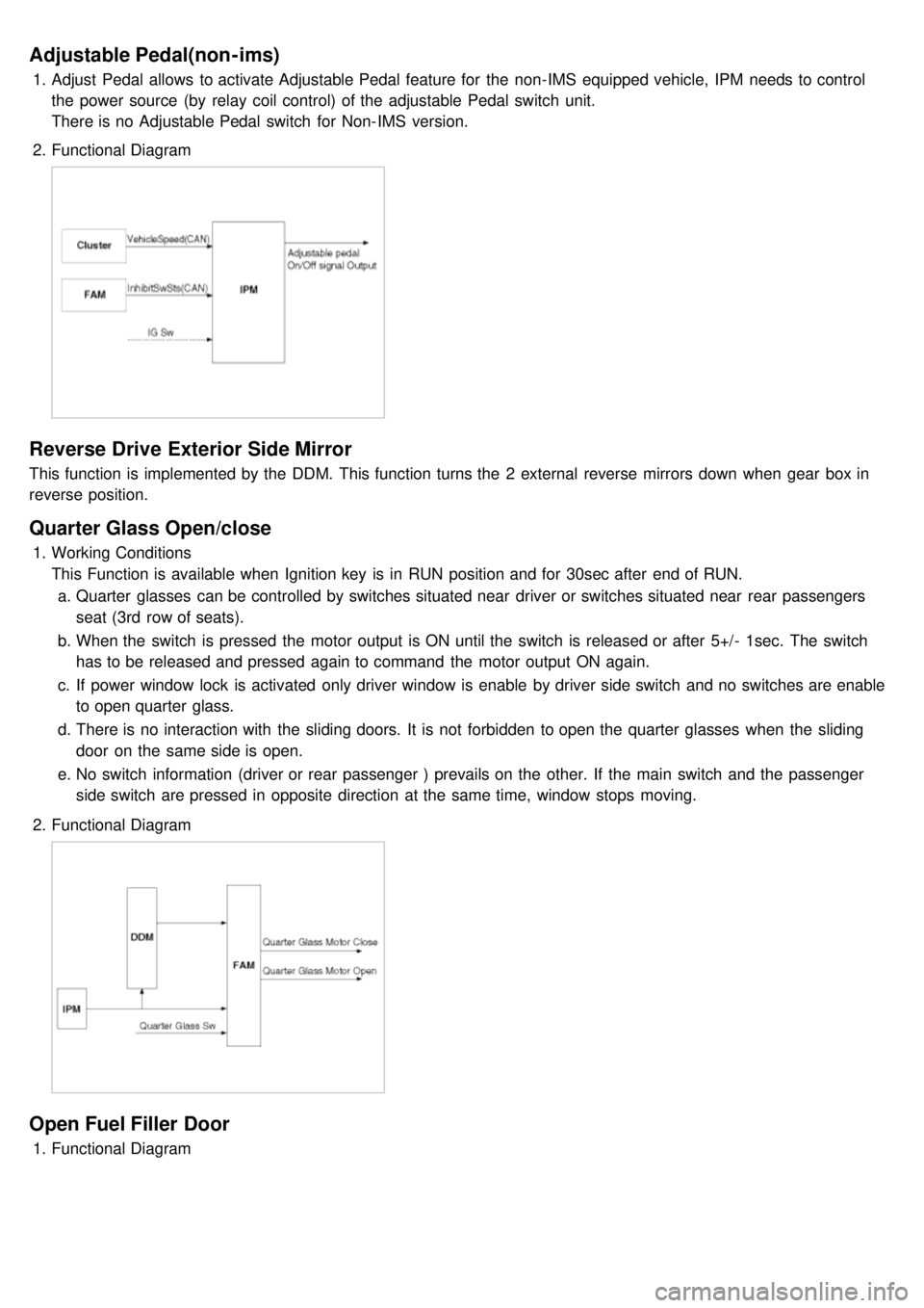
1.Adjust Pedal allows to activate Adjustable Pedal feature for the non- IMS equipped vehicle, IPM needs to control
the power source (by relay coil control) of the adjustable Pedal switch unit.
There is no Adjustable Pedal switch for Non- IMS version.
2. Functional Diagram
Reverse Drive Exterior Side Mirror
This function is implemented by the DDM. This function turns the 2 external reverse mirrors down when gear box in
reverse position.
Quarter Glass Open/close
1.Working Conditions
This Function is available when Ignition key is in RUN position and for 30sec after end of RUN.
a. Quarter glasses can be controlled by switches situated near driver or switches situated near rear passengers
seat (3rd row of seats).
b. When the switch is pressed the motor output is ON until the switch is released or after 5+/- 1sec. The switch
has to be released and pressed again to command the motor output ON again.
c. If power window lock is activated only driver window is enable by driver side switch and no switches are enable
to open quarter glass.
d. There is no interaction with the sliding doors. It is not forbidden to open the quarter glasses when the sliding
door on the same side is open.
e. No switch information (driver or rear passenger ) prevails on the other. If the main switch and the passenger
side switch are pressed in opposite direction at the same time, window stops moving.
2. Functional Diagram
Open Fuel Filler Door
1.Functional Diagram
Page 1226 of 1575
Sun Roof Relay Coil
This function defines the condition for switching on or off power feed to sun roof relay coil. This function is available in
RUN position and during after run timer ON.
Power Window Timer
This function defines the conditions for allowing use of power windows, quarter glass, and feed to sunroof relay coil.
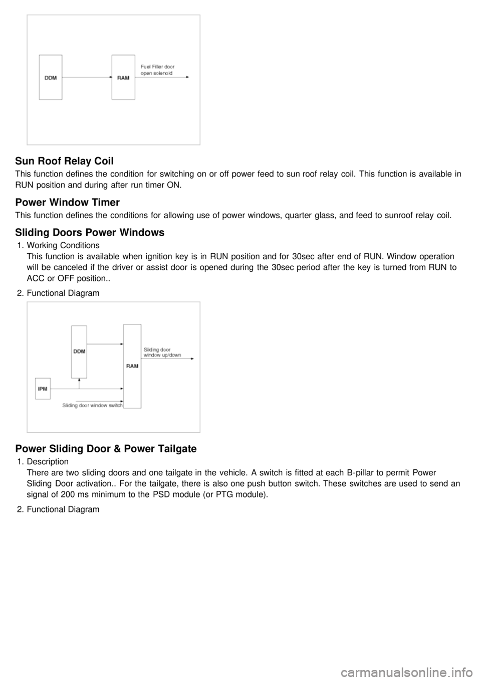
Sliding Doors Power Windows
1.Working Conditions
This function is available when ignition key is in RUN position and for 30sec after end of RUN. Window operation
will be canceled if the driver or assist door is opened during the 30sec period after the key is turned from RUN to
ACC or OFF position..
2. Functional Diagram
Power Sliding Door & Power Tailgate
1.Description
There are two sliding doors and one tailgate in the vehicle. A switch is fitted at each B- pillar to permit Power
Sliding Door activation.. For the tailgate, there is also one push button switch. These switches are used to send an
signal of 200 ms minimum to the PSD module (or PTG module).
2. Functional Diagram
Page 1229 of 1575
switch, the status of the ABS EBD warning, the status of the brake fluid sensor and the speed of the vehicle.
The IPM sends the park brake indicator control on the CAN network.
The indicator is lighted if the vacuum switch or ABS EBD warning are on or brake fluid sensor is low or park brake
switch is on.
If the speed of the vehicle is over 10 km/h and ignition switch is on the status RUN the park brake indicator control is
blinking at 50% duty in 0.6 second if Parking Brake switch Input is active. In this case Vacuum switch, ABS EBD
warning and Brake Fluid sensor are ignored.
The park brake indicator is blinking on the same time that the chime is ringing. If a CAN signal among Vacuum switch,
EBD warning or Brake Fluid Sens switch is INVALID, out of range or not received this CAN signal is considered to be
OFF.
If VehicleSpeed CAN signal is INVALID or not received, it is considered to be 0 kph.
Charging Voltage Control
The IPM receives on analog input the voltage of generator and sends a warning.
When the voltage of generator L pass strictly above 10V, the state of the CAN variable.
Turn Indicators Status
The status of the turn indicators are sent on the CAN network when the CAN network is available.
High Beam Status
The status of the high beam is sent on the CAN network when the CAN network is available.
Front Fog Lamp Status
The status of the front fog lamp (lightning and state of the bulbs) is sent on the CAN network when the CAN network
is available.
Doors Open Warning
The RAM receives on digital input the status of the driver door open switch and sends it on the CAN network.
The RAM receives on digital input the status of the passenger door open switch and sends it on the CAN network.
The RAM receives on digital input the status of the left sliding door open switch and sends it on the CAN network.
The RAM receives on digital input the status of the right sliding door open switch and sends it on the CAN network.
When vehicle speed is under 10 kph, with ignition key not inserted and any door OPEN, DoorsOpenWngCtrl stays ON
for 20 min and then is turned OFF.
Tailgate Open Switch Status
When vehicle speed is under 10 kph, ignition key is inserted and Tailgate open switch is OPEN, Tailgate Open
warning stays ON forever (IPM can enter sleep mode).
When vehicle speed is under 10 kph, with ignition key not inserted and lgate open switch is OPEN, Tailgate Open
warning stays ON for 20 min and then is turned OFF.
Chime Control
1.The chime warns the driver that a problem is occurred.
These warning are:
a. Seat belt
b. Parking on
c. Over speed
d. Key reminder
e. Light Warning
f. Doors Open
g. Tailgate open warning
2. Chime sound priority:
a. 1st : Seatbelt warning
b. 2nd : Overspeed warning
c. 3rd : Door open warning
d. 4th : T/Gate open warning
e. 5th : Key operated warning
f. 6th : Parking Brake warning
Page 1230 of 1575
g.7th : Light ON warning
h. 8th : Key learning sound
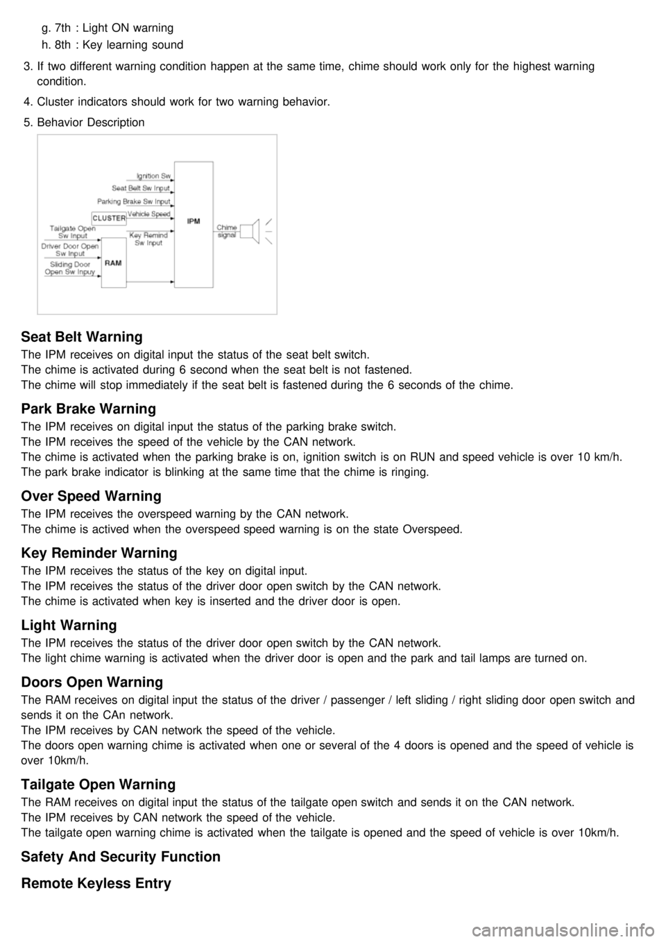
3. If two different warning condition happen at the same time, chime should work only for the highest warning
condition.
4. Cluster indicators should work for two warning behavior.
5. Behavior Description
Seat Belt Warning
The IPM receives on digital input the status of the seat belt switch.
The chime is activated during 6 second when the seat belt is not fastened.
The chime will stop immediately if the seat belt is fastened during the 6 seconds of the chime.
Park Brake Warning
The IPM receives on digital input the status of the parking brake switch.
The IPM receives the speed of the vehicle by the CAN network.
The chime is activated when the parking brake is on, ignition switch is on RUN and speed vehicle is over 10 km/h.
The park brake indicator is blinking at the same time that the chime is ringing.
Over Speed Warning
The IPM receives the overspeed warning by the CAN network.
The chime is actived when the overspeed speed warning is on the state Overspeed.
Key Reminder Warning
The IPM receives the status of the key on digital input.
The IPM receives the status of the driver door open switch by the CAN network.
The chime is activated when key is inserted and the driver door is open.
Light Warning
The IPM receives the status of the driver door open switch by the CAN network.
The light chime warning is activated when the driver door is open and the park and tail lamps are turned on.
Doors Open Warning
The RAM receives on digital input the status of the driver / passenger / left sliding / right sliding door open switch and
sends it on the CAn network.
The IPM receives by CAN network the speed of the vehicle.
The doors open warning chime is activated when one or several of the 4 doors is opened and the speed of vehicle is
over 10km/h.
Tailgate Open Warning
The RAM receives on digital input the status of the tailgate open switch and sends it on the CAN network.
The IPM receives by CAN network the speed of the vehicle.
The tailgate open warning chime is activated when the tailgate is opened and the speed of vehicle is over 10km/h.
Safety And Security Function
Remote Keyless Entry
Page 1231 of 1575
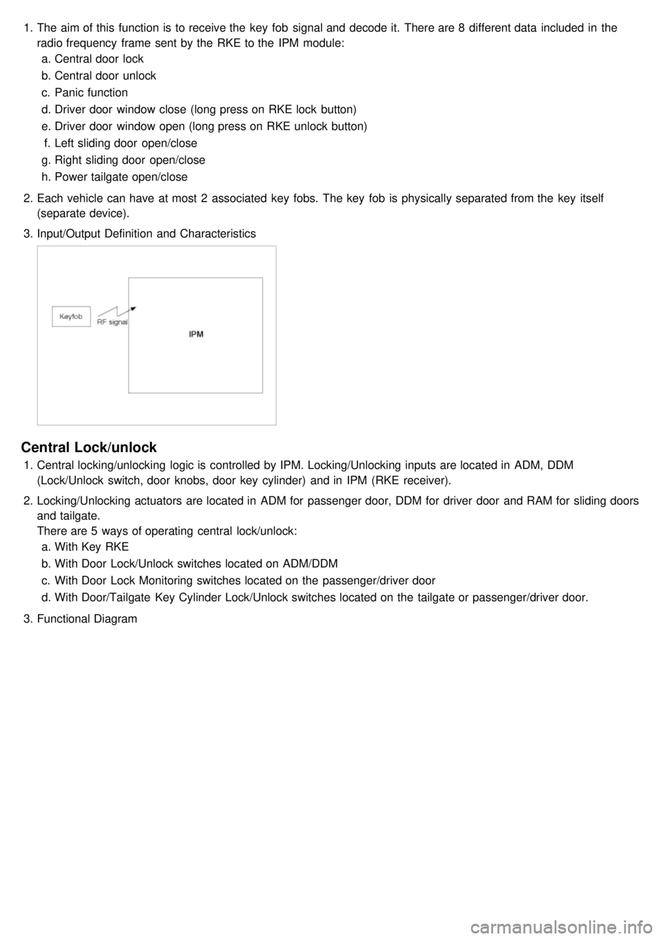
1.The aim of this function is to receive the key fob signal and decode it. There are 8 different data included in the
radio frequency frame sent by the RKE to the IPM module:
a. Central door lock
b. Central door unlock
c. Panic function
d. Driver door window close (long press on RKE lock button)
e. Driver door window open (long press on RKE unlock button)
f. Left sliding door open/close
g. Right sliding door open/close
h. Power tailgate open/close
2. Each vehicle can have at most 2 associated key fobs. The key fob is physically separated from the key itself
(separate device).
3. Input/Output Definition and Characteristics
Central Lock/unlock
1.Central locking/unlocking logic is controlled by IPM. Locking/Unlocking inputs are located in ADM, DDM
(Lock/Unlock switch, door knobs, door key cylinder) and in IPM (RKE receiver).
2. Locking/Unlocking actuators are located in ADM for passenger door, DDM for driver door and RAM for sliding doors
and tailgate.
There are 5 ways of operating central lock/unlock:
a. With Key RKE
b. With Door Lock/Unlock switches located on ADM/DDM
c. With Door Lock Monitoring switches located on the passenger/driver door
d. With Door/Tailgate Key Cylinder Lock/Unlock switches located on the tailgate or passenger/driver door.
3. Functional Diagram
Page 1243 of 1575
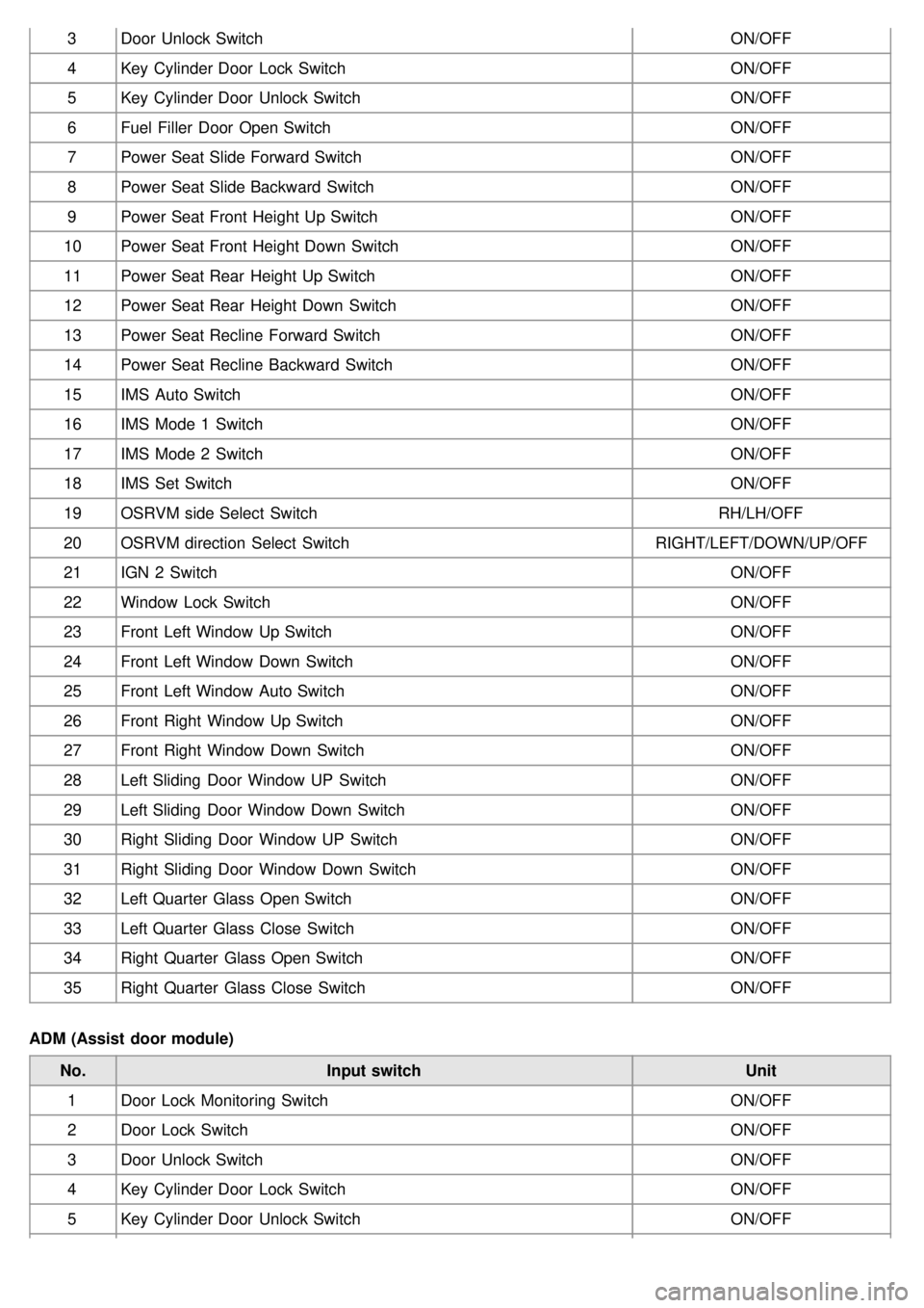
3Door Unlock Switch ON/OFF
4 Key Cylinder Door Lock Switch ON/OFF
5 Key Cylinder Door Unlock Switch ON/OFF
6 Fuel Filler Door Open Switch ON/OFF
7 Power Seat Slide Forward Switch ON/OFF
8 Power Seat Slide Backward Switch ON/OFF
9 Power Seat Front Height Up Switch ON/OFF
10 Power Seat Front Height Down Switch ON/OFF
11 Power Seat Rear Height Up Switch ON/OFF
12 Power Seat Rear Height Down Switch ON/OFF
13 Power Seat Recline Forward Switch ON/OFF
14 Power Seat Recline Backward Switch ON/OFF
15 IMS Auto Switch ON/OFF
16 IMS Mode 1 Switch ON/OFF
17 IMS Mode 2 Switch ON/OFF
18 IMS Set Switch ON/OFF
19 OSRVM side Select Switch RH/LH/OFF
20 OSRVM direction Select Switch RIGHT/LEFT/DOWN/UP/OFF
21 IGN 2 Switch ON/OFF
22 Window Lock Switch ON/OFF
23 Front Left Window Up Switch ON/OFF
24 Front Left Window Down Switch ON/OFF
25 Front Left Window Auto Switch ON/OFF
26 Front Right Window Up Switch ON/OFF
27 Front Right Window Down Switch ON/OFF
28 Left Sliding Door Window UP Switch ON/OFF
29 Left Sliding Door Window Down Switch ON/OFF
30 Right Sliding Door Window UP Switch ON/OFF
31 Right Sliding Door Window Down Switch ON/OFF
32 Left Quarter Glass Open Switch ON/OFF
33 Left Quarter Glass Close Switch ON/OFF
34 Right Quarter Glass Open Switch ON/OFF
35 Right Quarter Glass Close Switch ON/OFF
ADM (Assist door module) No. Input switch Unit
1 Door Lock Monitoring Switch ON/OFF
2 Door Lock Switch ON/OFF
3 Door Unlock Switch ON/OFF
4 Key Cylinder Door Lock Switch ON/OFF
5 Key Cylinder Door Unlock Switch ON/OFF
Page 1315 of 1575
2007 > 2.7L V6 GASOLINE >
INSPECTION
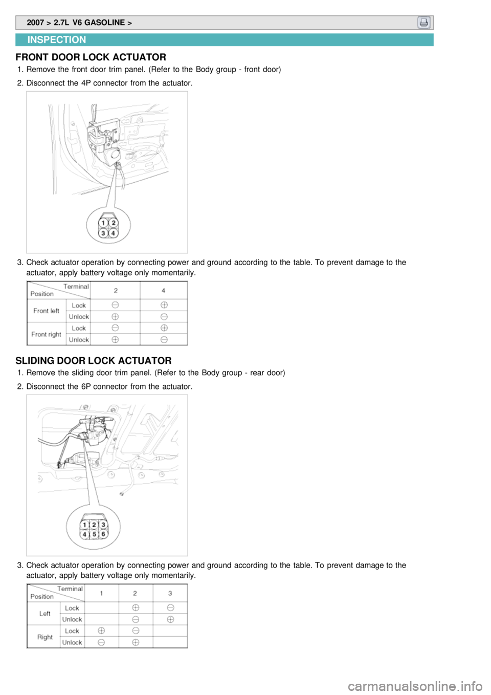
FRONT DOOR LOCK ACTUATOR
1. Remove the front door trim panel. (Refer to the Body group - front door)
2. Disconnect the 4P connector from the actuator.
3.Check actuator operation by connecting power and ground according to the table. To prevent damage to the
actuator, apply battery voltage only momentarily.
SLIDING DOOR LOCK ACTUATOR
1.Remove the sliding door trim panel. (Refer to the Body group - rear door)
2. Disconnect the 6P connector from the actuator.
3.Check actuator operation by connecting power and ground according to the table. To prevent damage to the
actuator, apply battery voltage only momentarily.
Page 1316 of 1575
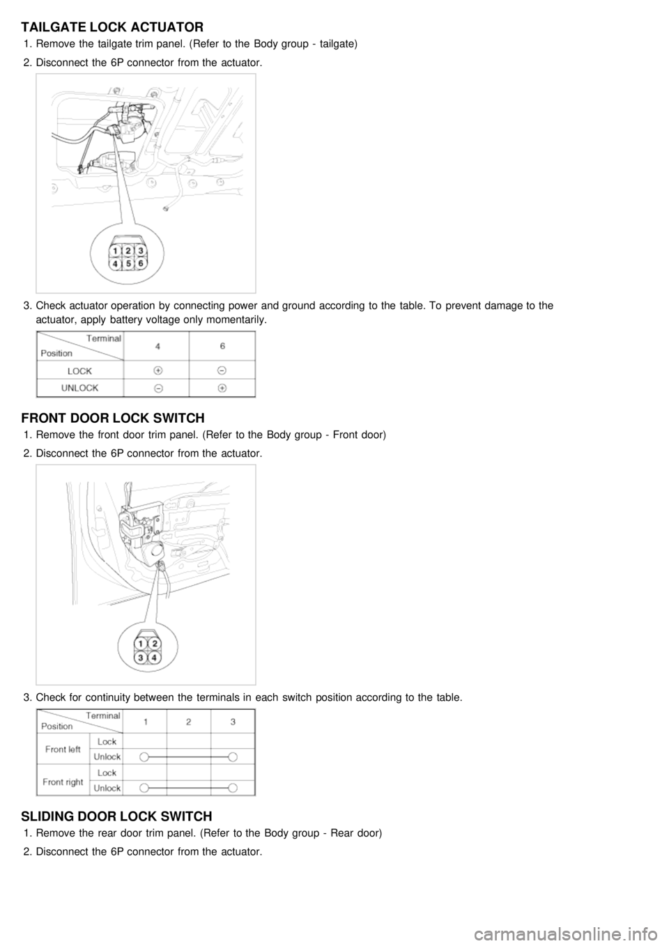
TAILGATE LOCK ACTUATOR
1.Remove the tailgate trim panel. (Refer to the Body group - tailgate)
2. Disconnect the 6P connector from the actuator.
3.Check actuator operation by connecting power and ground according to the table. To prevent damage to the
actuator, apply battery voltage only momentarily.
FRONT DOOR LOCK SWITCH
1.Remove the front door trim panel. (Refer to the Body group - Front door)
2. Disconnect the 6P connector from the actuator.
3.Check for continuity between the terminals in each switch position according to the table.
SLIDING DOOR LOCK SWITCH
1.Remove the rear door trim panel. (Refer to the Body group - Rear door)
2. Disconnect the 6P connector from the actuator.