Page 941 of 1575

be probably an open in the HECU power circuit or an open in the
diagnosis output circuit.b.
Inoperative HECU
c. Inoperative power source circuit
INSPECTION PROCEDURES
CHECK FOR CONTINUITY IN THE DIAGNOSIS LINE
1. Disconnect the connector from the ABS control module.
2. Check for continuity between terminals 11 of the ABS control module connector and 1 of the data link connector.
Is there continuity?
▶ Check the power source of ABS control module.
▶ Repair an open in the wire.
CHECK THE POWER SOURCE OF ABS CONTROL MODULE
1. Disconnect the connector from the ABS control module.
2. Turn the ignition switch ON, measure the voltage between terminal 18 of the ABS control module harness side
connector and body ground.
Specification: approximately B+
Is voltage within specification?
▶ Check for poor ground.
▶ Check the harness or connector between the fuse (10A) in the engine compartment junction block and the ABS
control module.Repair if necessary.
CHECK FOR POOR GROUND
Check for continuity between terminal 5 of the data link connector and ground point.
▶ Replace the ABS control module and recheck.
▶ Repair an open in the wire or poor ground.
Page 942 of 1575

DETECTING CONDITIONTrouble Symptoms Possible Cause
When current flows in the HECU the ABS warning lamp turns from
ON to OFF as the initial check.Therefore if the lamp does not light up,
the cause may be an open in the lamp power supply circuit, a blown
bulb, an open in the both circuits between the ABS warning lamp and
the HECU, and the inoperative HECU. a.
Inoperative ABS warning lamp bulb
b. Blown No.2 fuse (10A) in the engine
compartment junction block
c. Inoperative ABS warning lamp module
d. Inoperative HECU
INSPECTION PROCEDURES
PROBLEM VERIFICATION
Disconnect the connector from the ABS control module and turn the ignition switch ON.
Does the ABS warning lamp light up?
▶ It is normal. Recheck the ABS control module.
▶ Check the power source for the ABS warning lamp.
CHECK THE POWER SOURCE FOR THE ABS WARNING LAMP
1. Disconnect the instrument cluster connector and turn the ignition switch ON.
2. Measure the voltage between terminal 8 of the cluster harness side connector and body ground.
Specification: approximately B+
Is voltage within specification?
▶ Repair bulb or instrument cluster assembly.
▶ Check for blown fuse.
Page 943 of 1575

CHECK FOR BLOWN FUSE
Check continuity of fuse (10A) from the engine compartment junction block.
Is there continuity?
▶ Repair an open in the wire between ABS fuse and 1 of cluster connector.
▶ Replace the blown fuse.
DETECTING CONDITION
Trouble Symptoms Possible Cause
If the HECU detects trouble, it lights the ABS warning lamp while at
the same time prohibiting ABS control. At this time, the HECU
records a DTC in memory.Even though the normal code is output, the
ABS warning lamp remains ON, then the cause may be probably an
open or short in the ABS warning lamp circuit. a.
An open in the wire
b. Inoperative instrument cluster assembly
c. Inoperative ABS warning lamp module
d. Inoperative HECU
INSPECTION PROCEDURES
CHECK DTC OUTPUT.
1. Connect the Scan Tool to the 16P data link connector located behind the driver's side kick panel.
2. Check the DTC output using Scan Tool.
Is DTC output ?
▶ Repair circuit indicated by code output.
▶ Check instrument cluster.
CHECK INSTRUMENT CLUSTER
Disconnect the cluster connector and turn the ignition switch ON.
Does the ABS warning lamp remains ON?
▶ Replace the instrument cluster.
▶ Check for open the wire.
CHECK FOR OPEN IN THE WIRE
Check for continuity in the wire between cluster and ABS control module.
Is there continuity?
▶ Replace the ABS control module and recheck.
▶ Repair an open in the wire between cluster and ABS control module.
BLEEDING OF BRAKE SYSTEM
1. Remove the reservoir cap and fill the brake reservoir with brake fluid.
If there is any brake fluid on any painted surface, wash it off immediately.
Page 1065 of 1575
2.Installation is the reverse the removal.
a.Make sure the connector is plugged in properly.
LOWER PANEL REPLACEMENT
1.Remove the crash pad side cover.
2. Remove the fuse box cover (A).
3.After loosening the crash pad lower panel mounting screws, then remove the lower panel (B).
4. Remove the parking brake lever (C).
[LHD]
Page 1152 of 1575

2007 > 2.7L V6 GASOLINE >
GENERAL TROUBLESHOOTING INFORMATION
BEFORE TROUBLESHOOTING
1. Check applicable fuses in the appropriate fuse/relay box.
2. Check the battery for damage, state of charge, and clean and tight connections.
a.Do not quick- charge a battery unless the battery ground cable has been disconnected, otherwise you will
damage the generator diodes.
b. Do not attempt to crank the engine with the battery ground cable loosely connected or you will severely
damage the wiring.
3. Check the generator belt tension.
HANDLING CONNECTORS
1.Make sure the connectors are clean and have no loose wire terminals.
2. Make sure multiple cavity connectors are packed with grease (except watertight connectors).
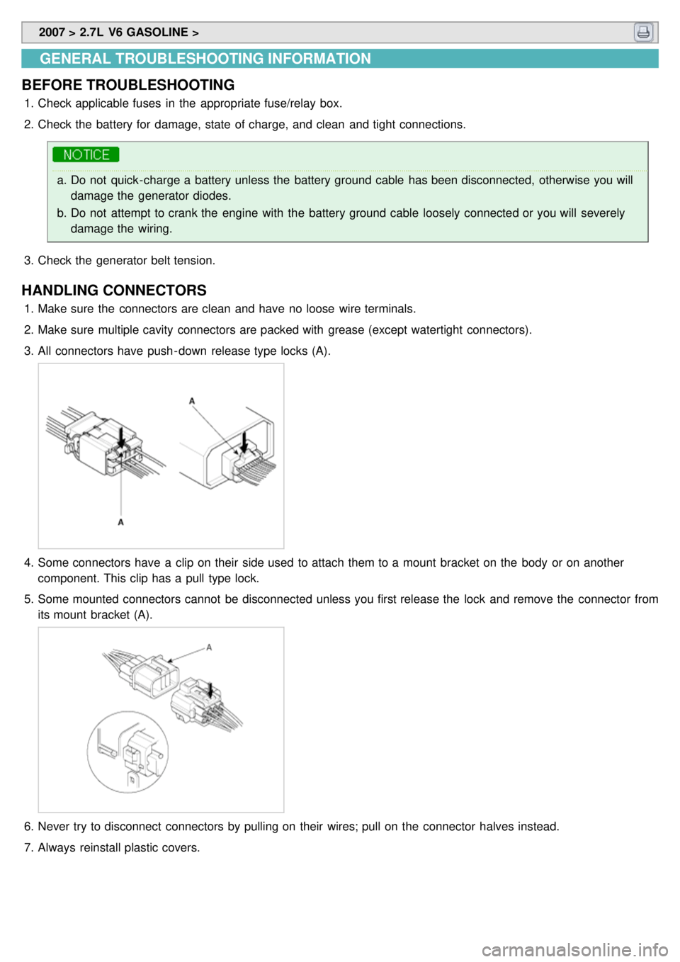
3. All connectors have push - down release type locks (A).
4.Some connectors have a clip on their side used to attach them to a mount bracket on the body or on another
component. This clip has a pull type lock.
5. Some mounted connectors cannot be disconnected unless you first release the lock and remove the connector from
its mount bracket (A).
6.Never try to disconnect connectors by pulling on their wires; pull on the connector halves instead.
7. Always reinstall plastic covers.
Page 1155 of 1575

TESTING AND REPAIRS
1.Do not use wires or harnesses with broken insulation.
Replace them or repair them by wrapping the break with electrical tape.
2. After installing parts, make sure that no wires are pinched under them.
3. When using electrical test equipment, follow the manufacturer's instructions and those described in this manual.
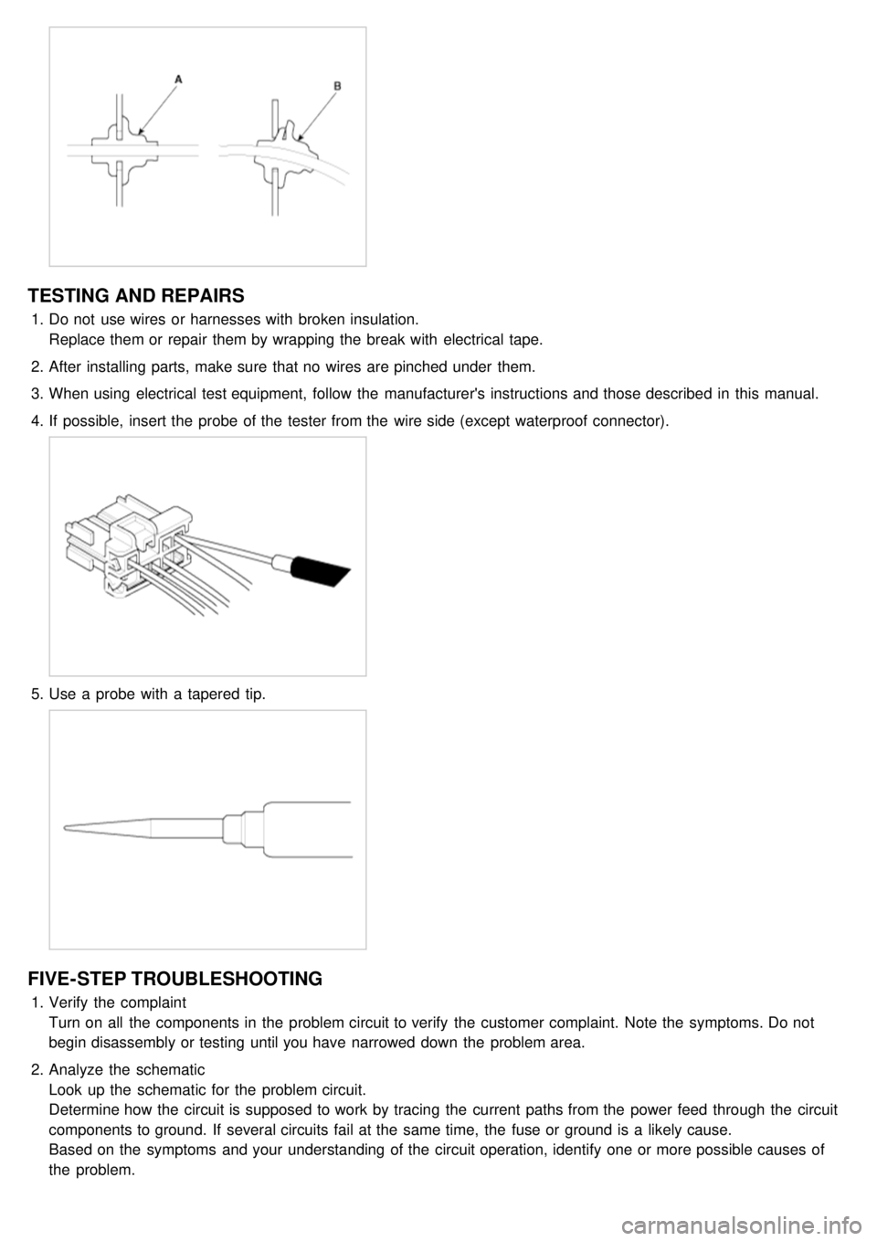
4. If possible, insert the probe of the tester from the wire side (except waterproof connector).
5.Use a probe with a tapered tip.
FIVE-STEP TROUBLESHOOTING
1.Verify the complaint
Turn on all the components in the problem circuit to verify the customer complaint. Note the symptoms. Do not
begin disassembly or testing until you have narrowed down the problem area.
2. Analyze the schematic
Look up the schematic for the problem circuit.
Determine how the circuit is supposed to work by tracing the current paths from the power feed through the circuit
components to ground. If several circuits fail at the same time, the fuse or ground is a likely cause.
Based on the symptoms and your understanding of the circuit operation, identify one or more possible causes of
the problem.
Page 1156 of 1575
3.Isolate the problem by testing the circuit
Make circuit tests to check the diagnosis you made in step 2. Keep in mind that a logical, simple procedure is the
key to efficient troubleshooting.
Test for the most likely cause of failure first. Try to make tests at points that are easily accessible.
4. Fix the problem
Once the specific problem is identified, make the repair. Be sure to use proper tools and safe procedures.
5. Make sure the circuit works
Turn on all components in the repaired circuit in all modes to make sure you've fixed the entire problem. If the
problem was a blown fuse, be sure to test all of the circuits on the fuse. Make sure no new problems turn up and
the original problem does not recur
Page 1242 of 1575

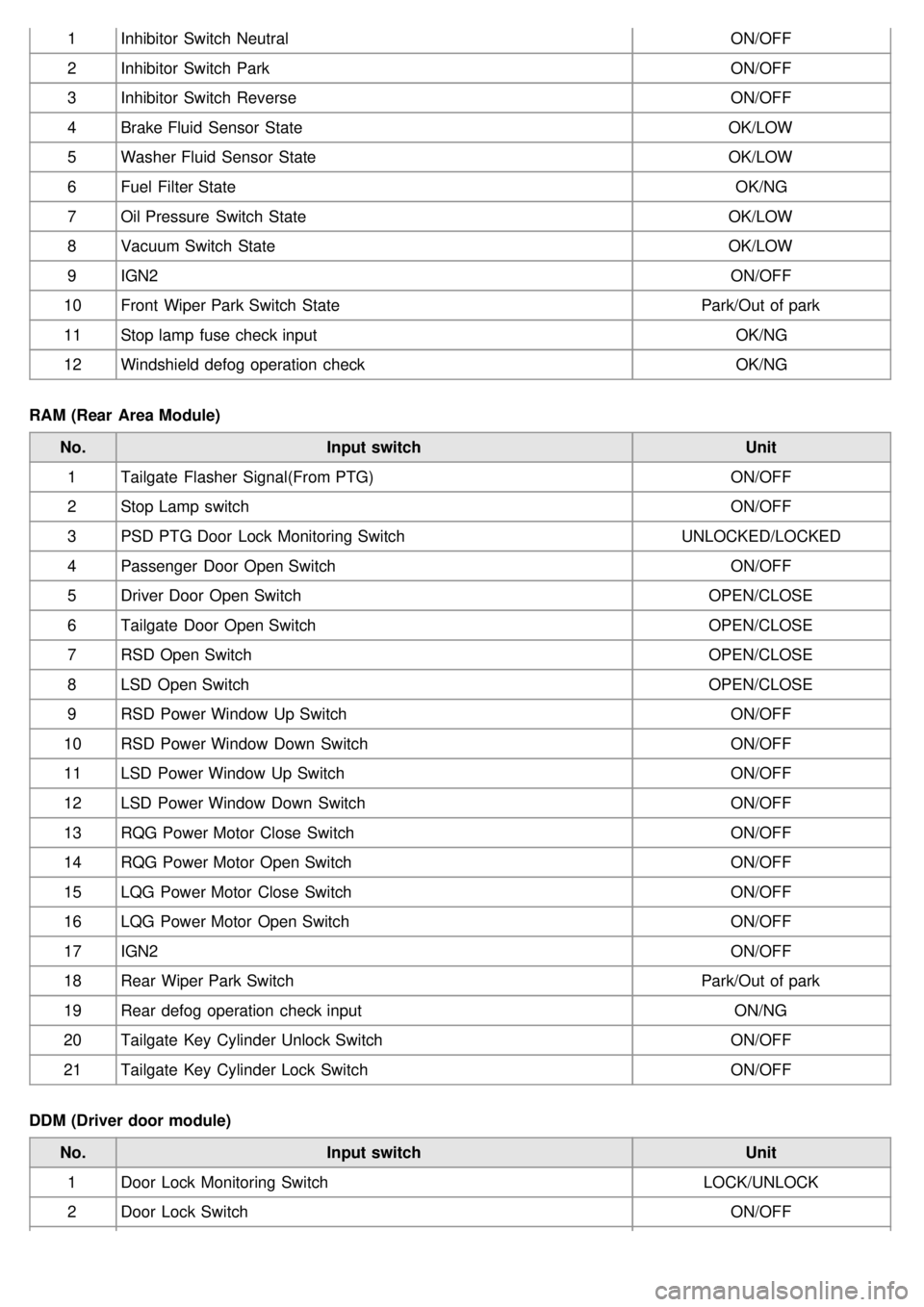
1Inhibitor Switch Neutral ON/OFF
2 Inhibitor Switch Park ON/OFF
3 Inhibitor Switch Reverse ON/OFF
4 Brake Fluid Sensor State OK/LOW
5 Washer Fluid Sensor State OK/LOW
6 Fuel Filter State OK/NG
7 Oil Pressure Switch State OK/LOW
8 Vacuum Switch State OK/LOW
9 IGN2 ON/OFF
10 Front Wiper Park Switch State Park/Out of park
11 Stop lamp fuse check input OK/NG
12 Windshield defog operation check OK/NG
RAM (Rear Area Module) No. Input switch Unit
1 Tailgate Flasher Signal(From PTG) ON/OFF
2 Stop Lamp switch ON/OFF
3 PSD PTG Door Lock Monitoring Switch UNLOCKED/LOCKED
4 Passenger Door Open Switch ON/OFF
5 Driver Door Open Switch OPEN/CLOSE
6 Tailgate Door Open Switch OPEN/CLOSE
7 RSD Open Switch OPEN/CLOSE
8 LSD Open Switch OPEN/CLOSE
9 RSD Power Window Up Switch ON/OFF
10 RSD Power Window Down Switch ON/OFF
11 LSD Power Window Up Switch ON/OFF
12 LSD Power Window Down Switch ON/OFF
13 RQG Power Motor Close Switch ON/OFF
14 RQG Power Motor Open Switch ON/OFF
15 LQG Power Motor Close Switch ON/OFF
16 LQG Power Motor Open Switch ON/OFF
17 IGN2 ON/OFF
18 Rear Wiper Park Switch Park/Out of park
19 Rear defog operation check input ON/NG
20 Tailgate Key Cylinder Unlock Switch ON/OFF
21 Tailgate Key Cylinder Lock Switch ON/OFF
DDM (Driver door module) No. Input switch Unit
1 Door Lock Monitoring Switch LOCK/UNLOCK
2 Door Lock Switch ON/OFF