2007 KIA CARNIVAL oil
[x] Cancel search: oilPage 1228 of 1575
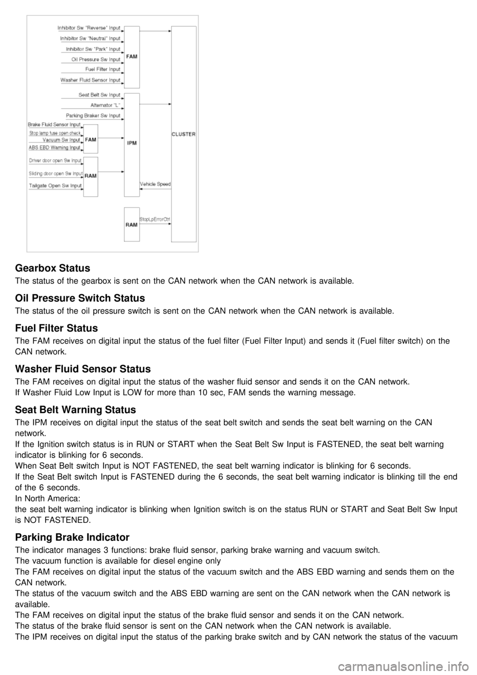
Gearbox Status
The status of the gearbox is sent on the CAN network when the CAN network is available.
Oil Pressure Switch Status
The status of the oil pressure switch is sent on the CAN network when the CAN network is available.
Fuel Filter Status
The FAM receives on digital input the status of the fuel filter (Fuel Filter Input) and sends it (Fuel filter switch) on the
CAN network.
Washer Fluid Sensor Status
The FAM receives on digital input the status of the washer fluid sensor and sends it on the CAN network.
If Washer Fluid Low Input is LOW for more than 10 sec, FAM sends the warning message.
Seat Belt Warning Status
The IPM receives on digital input the status of the seat belt switch and sends the seat belt warning on the CAN
network.
If the Ignition switch status is in RUN or START when the Seat Belt Sw Input is FASTENED, the seat belt warning
indicator is blinking for 6 seconds.
When Seat Belt switch Input is NOT FASTENED, the seat belt warning indicator is blinking for 6 seconds.
If the Seat Belt switch Input is FASTENED during the 6 seconds, the seat belt warning indicator is blinking till the end
of the 6 seconds.
In North America:
the seat belt warning indicator is blinking when Ignition switch is on the status RUN or START and Seat Belt Sw Input
is NOT FASTENED.
Parking Brake Indicator
The indicator manages 3 functions: brake fluid sensor, parking brake warning and vacuum switch.
The vacuum function is available for diesel engine only
The FAM receives on digital input the status of the vacuum switch and the ABS EBD warning and sends them on the
CAN network.
The status of the vacuum switch and the ABS EBD warning are sent on the CAN network when the CAN network is
available.
The FAM receives on digital input the status of the brake fluid sensor and sends it on the CAN network.
The status of the brake fluid sensor is sent on the CAN network when the CAN network is available.
The IPM receives on digital input the status of the parking brake switch and by CAN network the status of the vacuum
switch, the status of the ABS EBD warning, the status of the brake fluid sensor and the speed of the vehicle.
Page 1242 of 1575
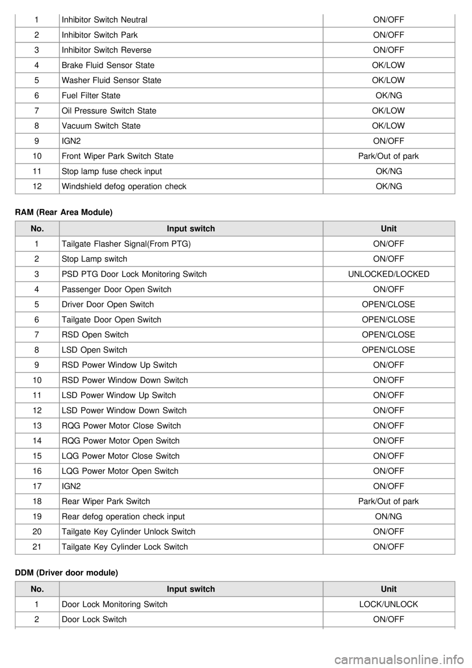
1Inhibitor Switch Neutral ON/OFF
2 Inhibitor Switch Park ON/OFF
3 Inhibitor Switch Reverse ON/OFF
4 Brake Fluid Sensor State OK/LOW
5 Washer Fluid Sensor State OK/LOW
6 Fuel Filter State OK/NG
7 Oil Pressure Switch State OK/LOW
8 Vacuum Switch State OK/LOW
9 IGN2 ON/OFF
10 Front Wiper Park Switch State Park/Out of park
11 Stop lamp fuse check input OK/NG
12 Windshield defog operation check OK/NG
RAM (Rear Area Module) No. Input switch Unit
1 Tailgate Flasher Signal(From PTG) ON/OFF
2 Stop Lamp switch ON/OFF
3 PSD PTG Door Lock Monitoring Switch UNLOCKED/LOCKED
4 Passenger Door Open Switch ON/OFF
5 Driver Door Open Switch OPEN/CLOSE
6 Tailgate Door Open Switch OPEN/CLOSE
7 RSD Open Switch OPEN/CLOSE
8 LSD Open Switch OPEN/CLOSE
9 RSD Power Window Up Switch ON/OFF
10 RSD Power Window Down Switch ON/OFF
11 LSD Power Window Up Switch ON/OFF
12 LSD Power Window Down Switch ON/OFF
13 RQG Power Motor Close Switch ON/OFF
14 RQG Power Motor Open Switch ON/OFF
15 LQG Power Motor Close Switch ON/OFF
16 LQG Power Motor Open Switch ON/OFF
17 IGN2 ON/OFF
18 Rear Wiper Park Switch Park/Out of park
19 Rear defog operation check input ON/NG
20 Tailgate Key Cylinder Unlock Switch ON/OFF
21 Tailgate Key Cylinder Lock Switch ON/OFF
DDM (Driver door module) No. Input switch Unit
1 Door Lock Monitoring Switch LOCK/UNLOCK
2 Door Lock Switch ON/OFF
Page 1248 of 1575
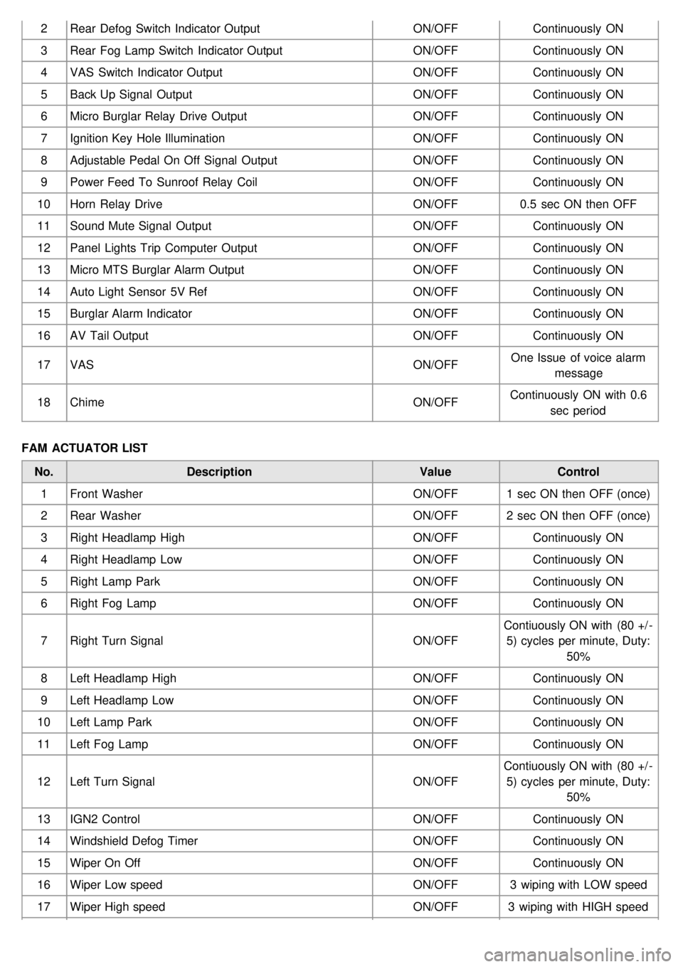
2Rear Defog Switch Indicator Output ON/OFFContinuously ON
3 Rear Fog Lamp Switch Indicator Output ON/OFFContinuously ON
4 VAS Switch Indicator Output ON/OFFContinuously ON
5 Back Up Signal Output ON/OFFContinuously ON
6 Micro Burglar Relay Drive Output ON/OFFContinuously ON
7 Ignition Key Hole Illumination ON/OFFContinuously ON
8 Adjustable Pedal On Off Signal Output ON/OFFContinuously ON
9 Power Feed To Sunroof Relay Coil ON/OFFContinuously ON
10 Horn Relay Drive ON/OFF0.5 sec ON then OFF
11 Sound Mute Signal Output ON/OFFContinuously ON
12 Panel Lights Trip Computer Output ON/OFFContinuously ON
13 Micro MTS Burglar Alarm Output ON/OFFContinuously ON
14 Auto Light Sensor 5V Ref ON/OFFContinuously ON
15 Burglar Alarm Indicator ON/OFFContinuously ON
16 AV Tail Output ON/OFFContinuously ON
17 VAS ON/OFFOne Issue of voice alarm
message
18 Chime ON/OFFContinuously ON with 0.6
sec period
FAM ACTUATOR LIST No. Description ValueControl
1 Front Washer ON/OFF1 sec ON then OFF (once)
2 Rear Washer ON/OFF2 sec ON then OFF (once)
3 Right Headlamp High ON/OFFContinuously ON
4 Right Headlamp Low ON/OFFContinuously ON
5 Right Lamp Park ON/OFFContinuously ON
6 Right Fog Lamp ON/OFFContinuously ON
7 Right Turn Signal ON/OFFContiuously ON with (80 +/ -
5) cycles per minute, Duty: 50%
8 Left Headlamp High ON/OFFContinuously ON
9 Left Headlamp Low ON/OFFContinuously ON
10 Left Lamp Park ON/OFFContinuously ON
11 Left Fog Lamp ON/OFFContinuously ON
12 Left Turn Signal ON/OFFContiuously ON with (80 +/ -
5) cycles per minute, Duty: 50%
13 IGN2 Control ON/OFFContinuously ON
14 Windshield Defog Timer ON/OFFContinuously ON
15 Wiper On Off ON/OFFContinuously ON
16 Wiper Low speed ON/OFF3 wiping with LOW speed
17 Wiper High speed ON/OFF3 wiping with HIGH speed
Page 1309 of 1575
Tolerance(rpm) 5,000
6,0007,0008,000Engine
Revolution (rpm) ±150
±180±210 -Gasoline
±150 ±150 --Diesel
FUEL GAUGE SENDER
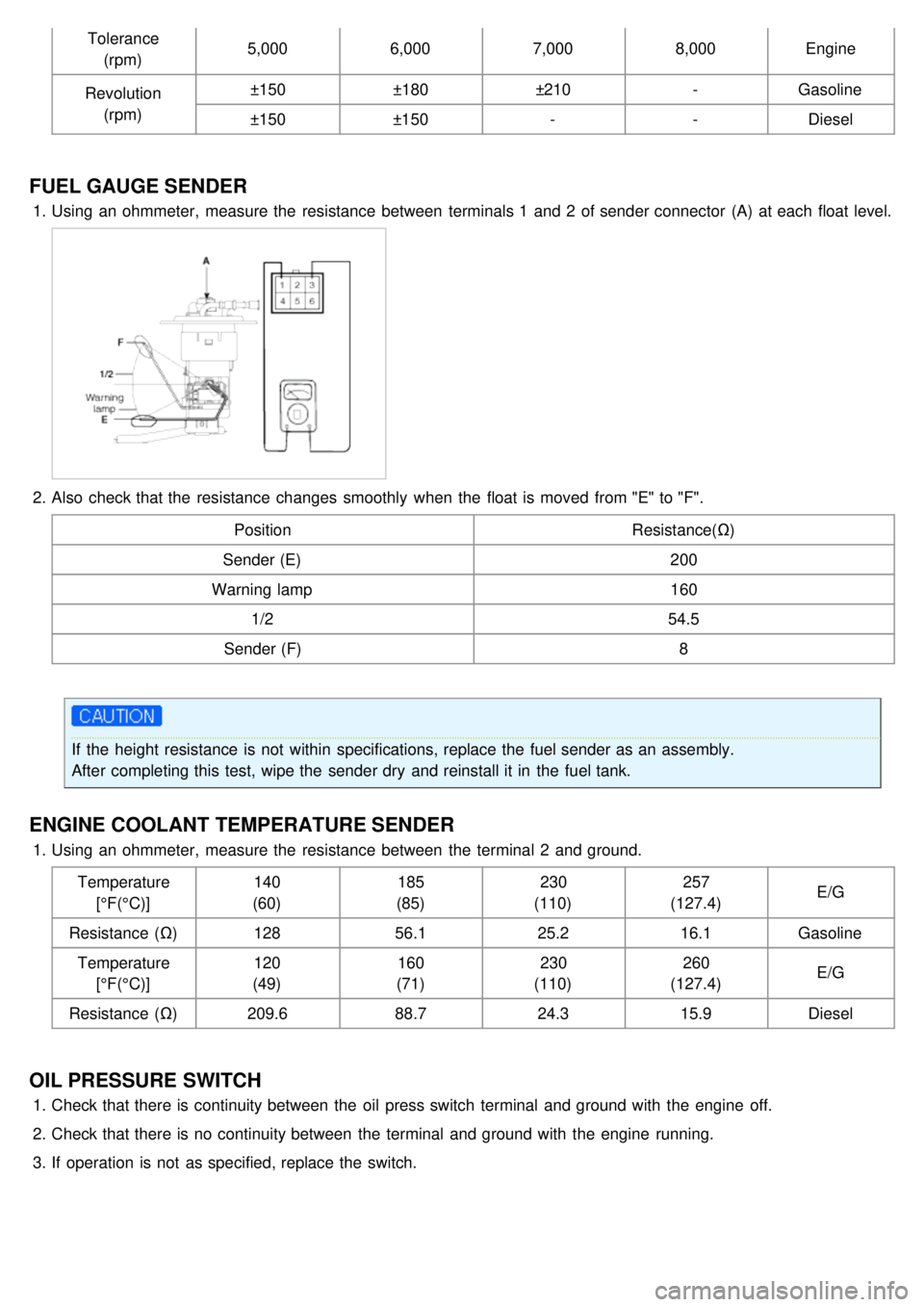
1.Using an ohmmeter, measure the resistance between terminals 1 and 2 of sender connector (A) at each float level.
2.Also check that the resistance changes smoothly when the float is moved from "E" to "F".
Position Resistance(Ω)
Sender (E) 200
Warning lamp 160
1/2 54.5
Sender (F) 8
If the height resistance is not within specifications, replace the fuel sender as an assembly.
After completing this test, wipe the sender dry and reinstall it in the fuel tank.
ENGINE COOLANT TEMPERATURE SENDER
1.Using an ohmmeter, measure the resistance between the terminal 2 and ground.
Temperature[°F(°C)] 140
(60) 185
(85) 230
(110) 257
(127.4) E/G
Resistance (Ω) 12856.1 25.216.1Gasoline
Temperature [°F(°C)] 120
(49) 160
(71) 230
(110) 260
(127.4) E/G
Resistance (Ω) 209.688.724.315.9Diesel
OIL PRESSURE SWITCH
1.Check that there is continuity between the oil press switch terminal and ground with the engine off.
2. Check that there is no continuity between the terminal and ground with the engine running.
3. If operation is not as specified, replace the switch.
Page 1310 of 1575
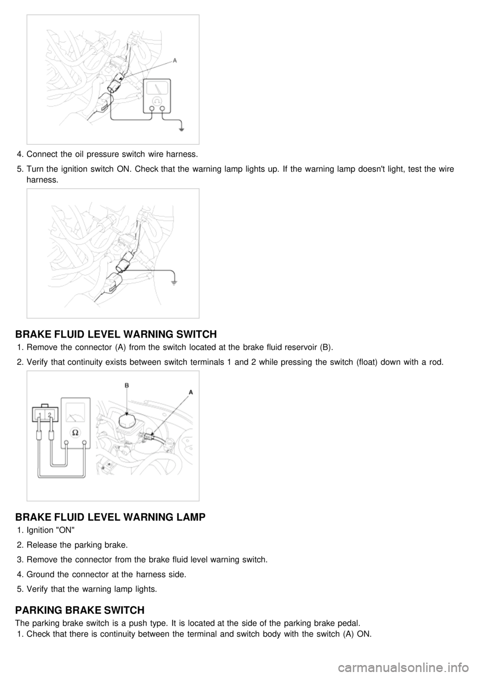
4.Connect the oil pressure switch wire harness.
5. Turn the ignition switch ON. Check that the warning lamp lights up. If the warning lamp doesn't light, test the wire
harness.
BRAKE FLUID LEVEL WARNING SWITCH
1.Remove the connector (A) from the switch located at the brake fluid reservoir (B).
2. Verify that continuity exists between switch terminals 1 and 2 while pressing the switch (float) down with a rod.
BRAKE FLUID LEVEL WARNING LAMP
1.Ignition "ON"
2. Release the parking brake.
3. Remove the connector from the brake fluid level warning switch.
4. Ground the connector at the harness side.
5. Verify that the warning lamp lights.
PARKING BRAKE SWITCH
The parking brake switch is a push type. It is located at the side of the parking brake pedal.
1. Check that there is continuity between the terminal and switch body with the switch (A) ON.
Page 1414 of 1575
2007 > 2.7L V6 GASOLINE >
INSPECTION
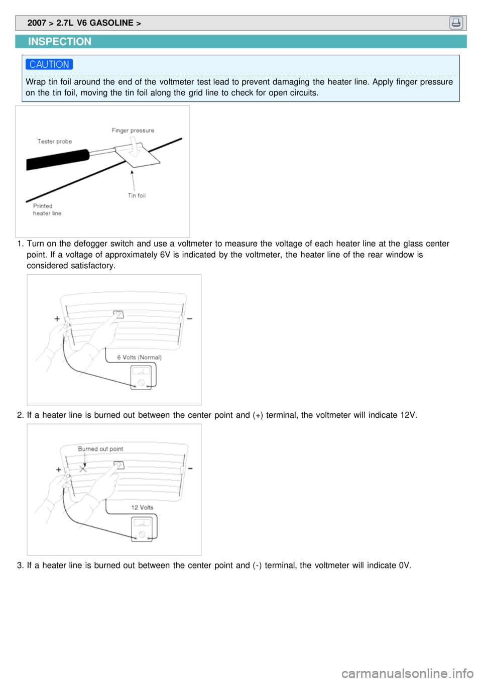
Wrap tin foil around the end of the voltmeter test lead to prevent damaging the heater line. Apply finger pressure
on the tin foil, moving the tin foil along the grid line to check for open circuits.
1.Turn on the defogger switch and use a voltmeter to measure the voltage of each heater line at the glass center
point. If a voltage of approximately 6V is indicated by the voltmeter, the heater line of the rear window is
considered satisfactory.
2.If a heater line is burned out between the center point and (+) terminal, the voltmeter will indicate 12V.
3.If a heater line is burned out between the center point and ( - ) terminal, the voltmeter will indicate 0V.
Page 1503 of 1575
2007 > 2.7L V6 GASOLINE >
DESCRIPTION
The immobilizer system will disable the vehicle unless the proper ignition key is used, in addition to the currently
available anti- theft systems such as car alarms, the immobilizer system aims to drastically reduce the rate of auto
theft.
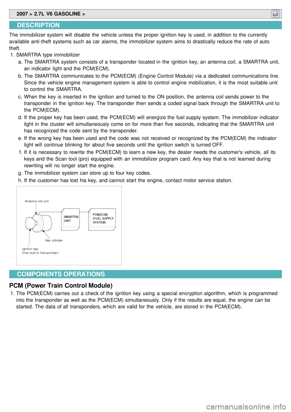
1. SMARTRA type immobilizer
a. The SMARTRA system consists of a transponder located in the ignition key, an antenna coil, a SMARTRA unit,
an indicator light and the PCM(ECM).
b. The SMARTRA communicates to the PCM(ECM) (Engine Control Module) via a dedicated communications line.
Since the vehicle engine management system is able to control engine mobilization, it is the most suitable unit
to control the SMARTRA.
c. When the key is inserted in the ignition and turned to the ON position, the antenna coil sends power to the
transponder in the ignition key. The transponder then sends a coded signal back through the SMARTRA unit to
the PCM(ECM).
d. If the proper key has been used, the PCM(ECM) will energize the fuel supply system. The immobilizer indicator
light in the cluster will simultaneously come on for more than five seconds, indicating that the SMARTRA unit
has recognized the code sent by the transponder.
e. If the wrong key has been used and the code was not received or recognized by the PCM(ECM) the indicator
light will continue blinking for about five seconds until the ignition switch is turned OFF.
f. If it is necessary to rewrite the PCM(ECM) to learn a new key, the dealer needs the customer's vehicle, all its
keys and the Scan tool (pro) equipped with an immobilizer program card. Any key that is not learned during
rewriting will no longer start the engine.
g. The immobilizer system can store up to four key codes.
h. If the customer has lost his key, and cannot start the engine, contact motor service station.
COMPONENTS OPERATIONS
PCM (Power Train Control Module)
1. The PCM(ECM) carries out a check of the ignition key using a special encryption algorithm, which is programmed
into the transponder as well as the PCM(ECM) simultaneously. Only if the results are equal, the engine can be
started. The data of all transponders, which are valid for the vehicle, are stored in the PCM(ECM).
Page 1504 of 1575
SMARTRA unit
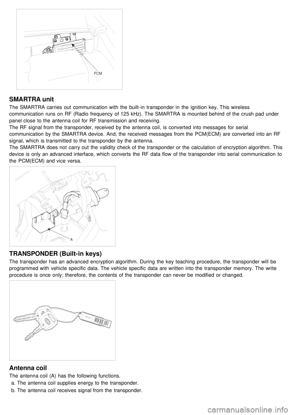
The SMARTRA carries out communication with the built- in transponder in the ignition key. This wireless
communication runs on RF (Radio frequency of 125 kHz). The SMARTRA is mounted behind of the crush pad under
panel close to the antenna coil for RF transmission and receiving.
The RF signal from the transponder, received by the antenna coil, is converted into messages for serial
communication by the SMARTRA device. And, the received messages from the PCM(ECM) are converted into an RF
signal, which is transmitted to the transponder by the antenna.
The SMARTRA does not carry out the validity check of the transponder or the calculation of encryption algorithm. This
device is only an advanced interface, which converts the RF data flow of the transponder into serial communication to
the PCM(ECM) and vice versa.
TRANSPONDER (Built-in keys)
The transponder has an advanced encryption algorithm. During the key teaching procedure, the transponder will be
programmed with vehicle specific data. The vehicle specific data are written into the transponder memory. The write
procedure is once only; therefore, the contents of the transponder can never be modified or changed.
Antenna coil
The antenna coil (A) has the following functions.a. The antenna coil supplies energy to the transponder.
b. The antenna coil receives signal from the transponder.