2007 KIA CARNIVAL remote start
[x] Cancel search: remote startPage 1214 of 1575
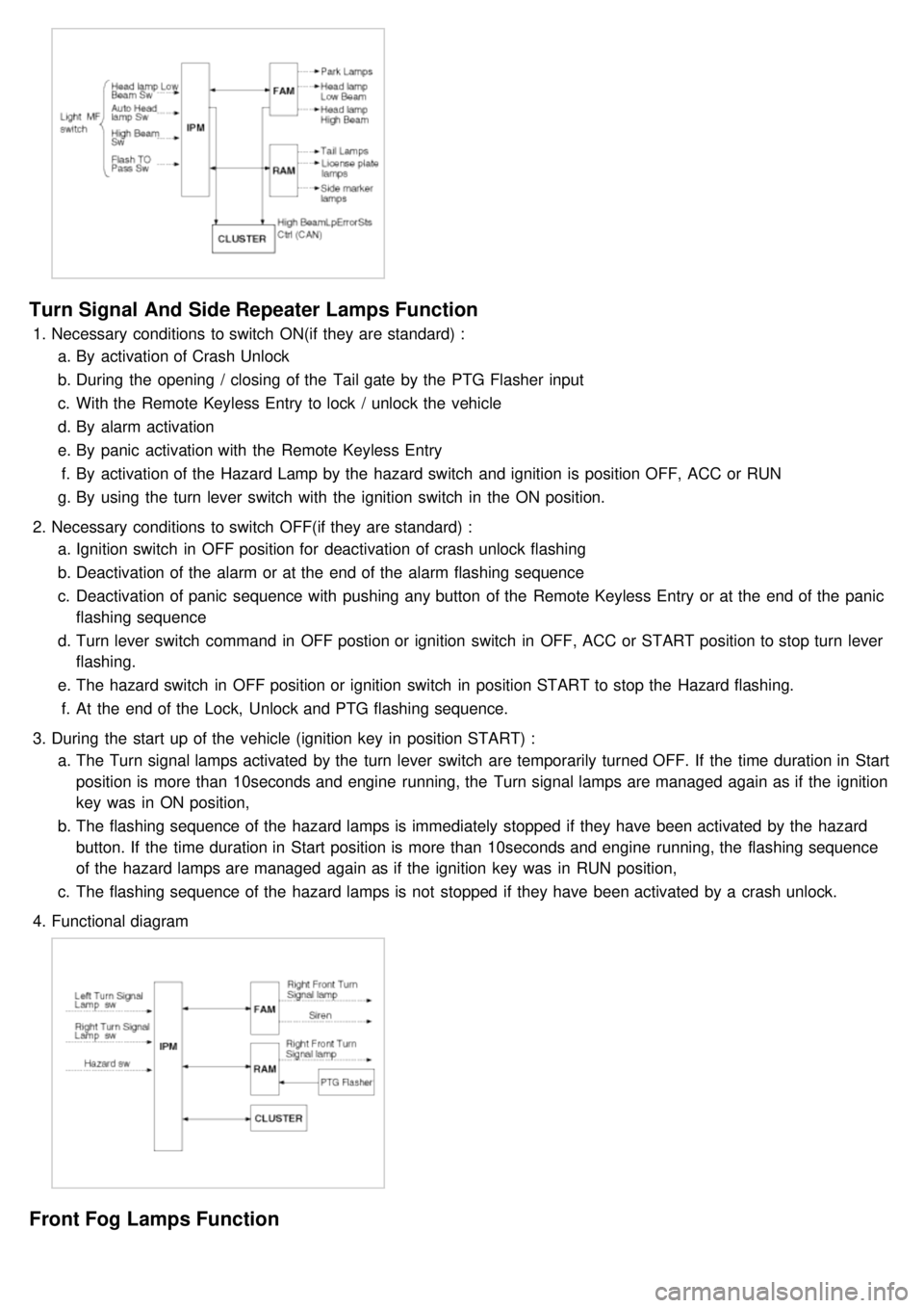
Turn Signal And Side Repeater Lamps Function
1.Necessary conditions to switch ON(if they are standard) :
a. By activation of Crash Unlock
b. During the opening / closing of the Tail gate by the PTG Flasher input
c. With the Remote Keyless Entry to lock / unlock the vehicle
d. By alarm activation
e. By panic activation with the Remote Keyless Entry
f. By activation of the Hazard Lamp by the hazard switch and ignition is position OFF, ACC or RUN
g. By using the turn lever switch with the ignition switch in the ON position.
2. Necessary conditions to switch OFF(if they are standard) :
a. Ignition switch in OFF position for deactivation of crash unlock flashing
b. Deactivation of the alarm or at the end of the alarm flashing sequence
c. Deactivation of panic sequence with pushing any button of the Remote Keyless Entry or at the end of the panic
flashing sequence
d. Turn lever switch command in OFF postion or ignition switch in OFF, ACC or START position to stop turn lever
flashing.
e. The hazard switch in OFF position or ignition switch in position START to stop the Hazard flashing.
f. At the end of the Lock, Unlock and PTG flashing sequence.
3. During the start up of the vehicle (ignition key in position START) :
a. The Turn signal lamps activated by the turn lever switch are temporarily turned OFF. If the time duration in Start
position is more than 10seconds and engine running, the Turn signal lamps are managed again as if the ignition
key was in ON position,
b. The flashing sequence of the hazard lamps is immediately stopped if they have been activated by the hazard
button. If the time duration in Start position is more than 10seconds and engine running, the flashing sequence
of the hazard lamps are managed again as if the ignition key was in RUN position,
c. The flashing sequence of the hazard lamps is not stopped if they have been activated by a crash unlock.
4. Functional diagram
Front Fog Lamps Function
Page 1218 of 1575
b.When the multifunction switch is not in postion headlamps turned on or autolight
c. 20 mn after the driver door is open
d. 20mn after IGN leaves the positions RUN to ACC or OFF
e. If IPM receives RKE "LOCK" command two times
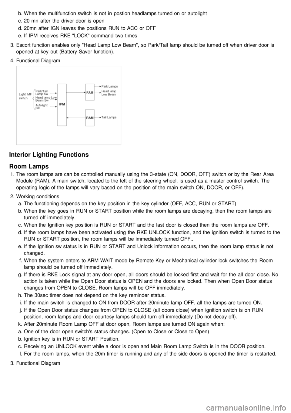
3. Escort function enables only "Head Lamp Low Beam", so Park/Tail lamp should be turned off when driver door is
opened at key out (Battery Saver function).
4. Functional Diagram
Interior Lighting Functions
Room Lamps
1.The room lamps are can be controlled manually using the 3 - state (ON, DOOR, OFF) switch or by the Rear Area
Module (RAM). A main switch, located to the left of the steering wheel, is used as a master control switch. The
operating logic of the lamps will vary based on the position of the main switch ON, DOOR, or OFF).
2. Working conditions
a. The functioning depends on the key position in the key cylinder (OFF, ACC, RUN or START)
b. When the key goes in RUN or START position while the room lamps are decaying, then the room lamps are
turned off immediately.
c. When the Ignition key position is RUN or START and the last door is closed then the room lamps are OFF.
d. If the room lamps have been activated using the RKE UNLOCK function, and the ignition switch is turned to the
RUN or START position, the room lamps will be immediately turned OFF..
e. If the Ignition sw status is in RUN or START and Unlock information occurs, then the room lamp status is not
changed.
f. When the system enters to ARM WAIT mode by Remote Key or Mechanical cylinder lock switches the Room
lamp should be turned off immediately.
g. If there is RKE Lock signal at any door open, all doors should be locked first and wait for the all door close. No
action is taken while the Open Door status is OPEN and the doors are locked. Then when Open Door status
changes from OPEN to CLOSE, Room lamps will be OFF immediately.
h. The 30sec timer does not depend on the key reminder status.
i. If the main switch is changed to ON from DOOR after 20minute lamp OFF, all the lamps are turned ON.
j. If the Open Door status changes from OPEN to CLOSE (all doors close) when ignition switch is on RUN
position, room lamps and door courtesy lamps should turn off immediately (Do not decay off).
k. After 20minute Room Lamp OFF at door open, Room lamps are turned ON again when:
a. One of the door open switch's status changes. (Open to Close or Close to Open)
b. Ignition key is in RUN or START Position.
c. Receiving an UNLOCK event while a door is open and Main Room Lamp Switch is in the DOOR position.
l. For the room lamps, when the 20m timer is running and any of the side doors is opened the timer is restarted.
3. Functional Diagram
Page 1232 of 1575
Key Reminder Unlock
1.Key reminder door unlock does not take into account the lock/unlock commands from RKE, key cylinder or door
lock switches. It only takes into account the state of the door lock monitoring switch, key reminder switch and door
open status in order to proceed with the unlock sequence or not.
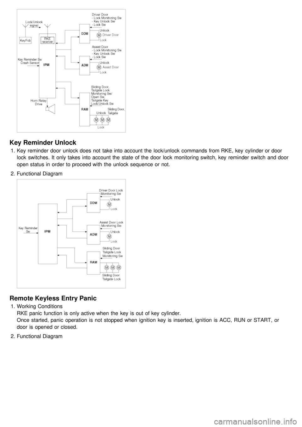
2. Functional Diagram
Remote Keyless Entry Panic
1.Working Conditions
RKE panic function is only active when the key is out of key cylinder.
Once started, panic operation is not stopped when ignition key is inserted, ignition is ACC, RUN or START, or
door is opened or closed.
2. Functional Diagram
Page 1336 of 1575
2007 > 2.7L V6 GASOLINE >
ADJUSTMENT
POWER SLIDING DOOR INITIALIZATION
A learn cycle must be performed whenever the power is removed, a Power Sliding Door component is removed or
replaced, or a sliding door adjustment is performed. The learn cycle enables the Power Sliding Door control module
(PSDM) to learn the range of full travel and effort required to power the Sliding Door which allows it to perform
properly and safely.
POWER SLIDING DOOR SYSTEM RESET
Certain conditions may require that the PSD system be reset 1. Remove the MEMORY fuse that provides power to the PSDM.
2. Wait 1 minute. Replace fuse. Initialize PSDM.
INITIALIZATION PROCEDURE
1.Manually close and latch the sliding door.
2. Power the sliding door open using the remote control, Open/Close switch, B- pillar switch, or handle.
3. Power the door close from full open to full closed position.
4. Power the door open again to full open position.
ALTERNATE METHOD
1.Remove the black connector (J2) from the PSDM.
2. Wait a short time. Replace connector. Initialize PSDM.
a.The PSD system initialization must start from the primary or secondary latched position.
b. Obstacle detection shall be active during Sliding Door initialization.
c. Work on level ground.
Page 1377 of 1575
2007 > 2.7L V6 GASOLINE >
ADJUSTMENT
POWER TAIL GATE INITIALIZATION
POWER TAILGATE SYSTEM RESET
Certain conditions may require that the PTG system be reset. 1. Remove the MEMORY fuse that provides logic power to the PTGM.
2. Wait 1 minute. Replace fuse. Initialize the PTGM.
INITIALIZATION PROCEDURE
The Power Tailgate system initialization must start from the full closed or latched position. The Tailgate must be
powered Open once to fully initialize the system (Obstacle detection shall be active during Tailgate initialization).
1. Manually close and latch the Tailgate.
2. Power the Tailgate open using the Open/Close switch, outside handle or the remote control.
ALTERNATE METHOD
1.Remove the black connector (J2) from the PTGM.
2. Wait a short time. Replace connector. Initialize PTGM.
a.The PTG system initialization must start from the primary or secondary latched position.
b. Obstacle detection shall be active during system initialization.