Page 866 of 1575

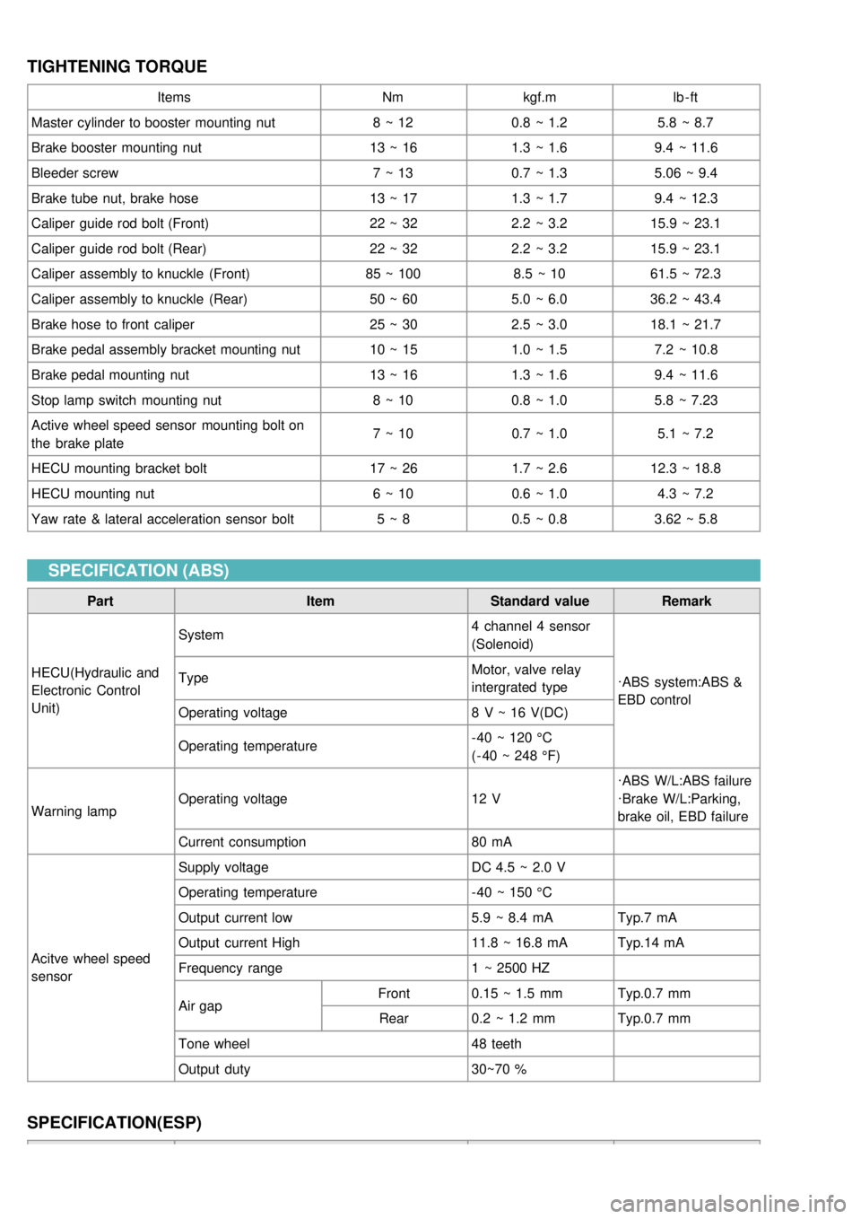
TIGHTENING TORQUE
ItemsNmkgf.m lb - ft
Master cylinder to booster mounting nut 8 ~ 120.8 ~ 1.2 5.8 ~ 8.7
Brake booster mounting nut 13 ~ 161.3 ~ 1.6 9.4 ~ 11.6
Bleeder screw 7 ~ 130.7 ~ 1.3 5.06 ~ 9.4
Brake tube nut, brake hose 13 ~ 171.3 ~ 1.7 9.4 ~ 12.3
Caliper guide rod bolt (Front) 22 ~ 322.2 ~ 3.215.9 ~ 23.1
Caliper guide rod bolt (Rear) 22 ~ 322.2 ~ 3.215.9 ~ 23.1
Caliper assembly to knuckle (Front) 85 ~ 1008.5 ~ 1061.5 ~ 72.3
Caliper assembly to knuckle (Rear) 50 ~ 605.0 ~ 6.036.2 ~ 43.4
Brake hose to front caliper 25 ~ 302.5 ~ 3.018.1 ~ 21.7
Brake pedal assembly bracket mounting nut 10 ~ 151.0 ~ 1.5 7.2 ~ 10.8
Brake pedal mounting nut 13 ~ 161.3 ~ 1.6 9.4 ~ 11.6
Stop lamp switch mounting nut 8 ~ 100.8 ~ 1.0 5.8 ~ 7.23
Active wheel speed sensor mounting bolt on
the brake plate 7 ~ 10
0.7 ~ 1.0 5.1 ~ 7.2
HECU mounting bracket bolt 17 ~ 261.7 ~ 2.612.3 ~ 18.8
HECU mounting nut 6 ~ 100.6 ~ 1.0 4.3 ~ 7.2
Yaw rate & lateral acceleration sensor bolt 5 ~ 80.5 ~ 0.8 3.62 ~ 5.8
SPECIFICATION (ABS)
Part ItemStandard valueRemark
HECU(Hydraulic and
Electronic Control
Unit) System
4 channel 4 sensor
(Solenoid)
·ABS system:ABS &
EBD control
Type
Motor, valve relay
intergrated type
Operating voltage 8 V ~ 16 V(DC)
Operating temperature - 40 ~ 120 °C
( - 40 ~ 248 °F)
Warning lamp Operating voltage
12 V·ABS W/L:ABS failure
·Brake W/L:Parking,
brake oil, EBD failure
Current consumption 80 mA
Acitve wheel speed
sensor Supply voltage
DC 4.5 ~ 2.0 V
Operating temperature - 40 ~ 150 °C
Output current low 5.9 ~ 8.4 mATyp.7 mA
Output current High 11.8 ~ 16.8 mATyp.14 mA
Frequency range 1 ~ 2500 HZ
Air gap Front
0.15 ~ 1.5 mm Typ.0.7 mm
Rear 0.2 ~ 1.2 mm Typ.0.7 mm
Tone wheel 48 teeth
Output duty 30~70 %
SPECIFICATION(ESP)
Page 889 of 1575
2.Tighten the brake tube (A) nut holding the brake hose (B) nut with a wrench.
3.Install the brake hose clip (A).
4.After installation, breed the air in the brake system.
Be careful not to damage the brake hose by sharp edges or tools.
INSPECTION
a.Check the brake tubes for cracks, crimps and corrosion.
b. Check the brake hoses for cracks, damaged and oil leakage.
c. Check the brake tube flare nuts for damage and oil leakage.
INSPECTION
a.Check the brake tubes for cracks, crimps and corrosion.
b. Check the brake hoses for cracks, damaged and oil leakage.
c. Check the brake tube flare nuts for damage and oil leakage.
Page 928 of 1575

2007 > 2.7L V6 GASOLINE >
DESCRIPTION
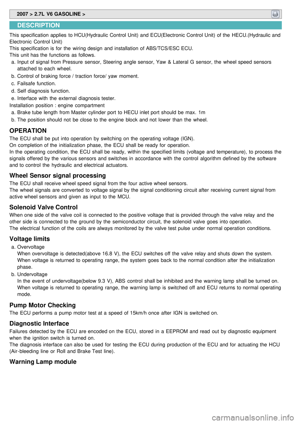
This specification applies to HCU(Hydraulic Control Unit) and ECU(Electronic Control Unit) of the HECU.(Hydraulic and
Electronic Control Unit)
This specification is for the wiring design and installation of ABS/TCS/ESC ECU.
This unit has the functions as follows.
a. Input of signal from Pressure sensor, Steering angle sensor, Yaw & Lateral G sensor, the wheel speed sensors
attached to each wheel.
b. Control of braking force / traction force/ yaw moment.
c. Failsafe function.
d. Self diagnosis function.
e. Interface with the external diagnosis tester.
Installation position : engine compartment a. Brake tube length from Master cylinder port to HECU inlet port should be max. 1m
b. The position should not be close to the engine block and not lower than the wheel.
OPERATION
The ECU shall be put into operation by switching on the operating voltage (IGN).
On completion of the initialization phase, the ECU shall be ready for operation.
In the operating condition, the ECU shall be ready, within the specified limits (voltage and temperature), to process the
signals offered by the various sensors and switches in accordance with the control algorithm defined by the software
and to control the hydraulic and electrical actuators.
Wheel Sensor signal processing
The ECU shall receive wheel speed signal from the four active wheel sensors.
The wheel signals are converted to voltage signal by the signal conditioning circuit after receiving current signal from
active wheel sensors and given as input to the MCU.
Solenoid Valve Control
When one side of the valve coil is connected to the positive voltage that is provided through the valve relay and the
other side is connected to the ground by the semiconductor circuit, the solenoid valve goes into operation.
The electrical function of the coils are always monitored by the valve test pulse under normal operation conditions.
Voltage limits
a.Overvoltage
When overvoltage is detected(above 16.8 V), the ECU switches off the valve relay and shuts down the system.
When voltage is returned to operating range, the system goes back to the normal condition after the initialization
phase.
b. Undervoltage
In the event of undervoltage(below 9.3 V), ABS control shall be inhibited and the warning lamp shall be turned on.
When voltage is returned to operating range, the warning lamp is switched off and ECU returns to normal operating
mode.
Pump Motor Checking
The ECU performs a pump motor test at a speed of 15km/h once after IGN is switched on.
Diagnostic Interface
Failures detected by the ECU are encoded on the ECU, stored in a EEPROM and read out by diagnostic equipment
when the ignition switch is turned on.
The diagnosis interface can also be used for testing the ECU during production of the ECU and for actuating the HCU
(Air - bleeding line or Roll and Brake Test line).
Warning Lamp module
Page 1097 of 1575
4.Remove the windshield (A) carefully using the glass holder (B)(09861- 31100).
INSTALLATION
1.With a knife, scrape the old adhesive smooth to a thickness of about 2mm (0.08 in.) on the bonding surface around
the entire windshield opening flange:
a. Do not scrape down to the painted surface of the body; damaged paint will interfere with proper bonding.
b. Remove the rubber dam and fastreners from the body.
c. Mask off surrounding surfaces before painting.
2. Clean the bonding surface with a sponge dampened in alcohol. After cleaning, keep oil, grease and water from
getting on the clean surface.
3. Install the windshield (A) upper molding (B) and fasteners (C). Do not allow any gaps.
Page 1182 of 1575
2007 > 2.7L V6 GASOLINE >
REPLACEMENT
1.Remove the right C filler trim(A) and luggage side trim. (Refer to Body group - Interior trim).
2.Remove the diversity(C) after removing 1P connector (A) and radio feeder cable (B).
3.Remove the glass antenna radio amplifier (A) - Left/Right each 1 ea- after removing radio feeder cable (B) and
amplifier wiring (C) from the glass antenna radio amplifier (A).
4.Installation is the reverse of removal.
INSPECTION
GLASS ANTENNA TEST
1. Wrap aluminum foil (A) around the tip of the tester probe (B) as shown.
Page 1225 of 1575

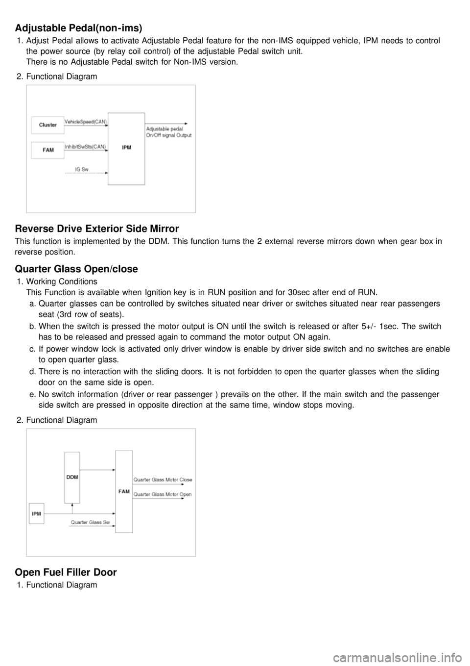
Adjustable Pedal(non-ims)
1.Adjust Pedal allows to activate Adjustable Pedal feature for the non- IMS equipped vehicle, IPM needs to control
the power source (by relay coil control) of the adjustable Pedal switch unit.
There is no Adjustable Pedal switch for Non- IMS version.
2. Functional Diagram
Reverse Drive Exterior Side Mirror
This function is implemented by the DDM. This function turns the 2 external reverse mirrors down when gear box in
reverse position.
Quarter Glass Open/close
1.Working Conditions
This Function is available when Ignition key is in RUN position and for 30sec after end of RUN.
a. Quarter glasses can be controlled by switches situated near driver or switches situated near rear passengers
seat (3rd row of seats).
b. When the switch is pressed the motor output is ON until the switch is released or after 5+/- 1sec. The switch
has to be released and pressed again to command the motor output ON again.
c. If power window lock is activated only driver window is enable by driver side switch and no switches are enable
to open quarter glass.
d. There is no interaction with the sliding doors. It is not forbidden to open the quarter glasses when the sliding
door on the same side is open.
e. No switch information (driver or rear passenger ) prevails on the other. If the main switch and the passenger
side switch are pressed in opposite direction at the same time, window stops moving.
2. Functional Diagram
Open Fuel Filler Door
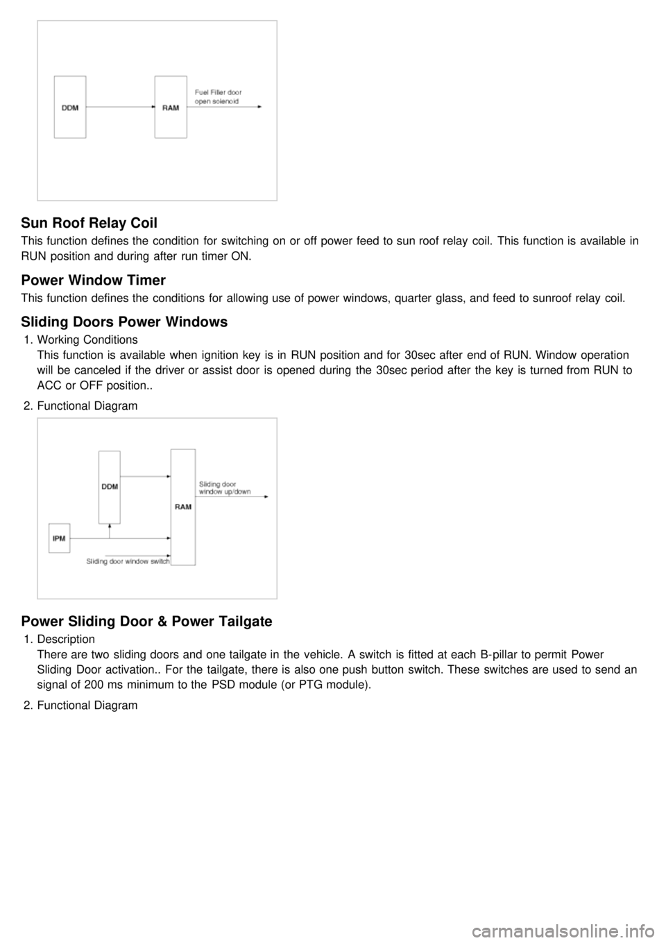
1.Functional Diagram
Page 1226 of 1575

Sun Roof Relay Coil
This function defines the condition for switching on or off power feed to sun roof relay coil. This function is available in
RUN position and during after run timer ON.
Power Window Timer
This function defines the conditions for allowing use of power windows, quarter glass, and feed to sunroof relay coil.
Sliding Doors Power Windows
1.Working Conditions
This function is available when ignition key is in RUN position and for 30sec after end of RUN. Window operation
will be canceled if the driver or assist door is opened during the 30sec period after the key is turned from RUN to
ACC or OFF position..
2. Functional Diagram
Power Sliding Door & Power Tailgate
1.Description
There are two sliding doors and one tailgate in the vehicle. A switch is fitted at each B- pillar to permit Power
Sliding Door activation.. For the tailgate, there is also one push button switch. These switches are used to send an
signal of 200 ms minimum to the PSD module (or PTG module).
2. Functional Diagram
Page 1227 of 1575
Easy Access
1.Description
The easy access function permits automatic rearward movement of the driver seat when the key is removed from
the cylinder. Automatic forward movement of the driver seat will take place when the key is inserted into the
cylinder. This function will be enabled on IMS equipped vehicles when the AUTO button is pressed.
Inhibit Switch should be in P- Position for the Easy Access operation.
2. Functional Diagram
Driver Information
Cluster Indicators
1.The instument cluster indicators listed below are controlled by the In- Panel Module (IPM), Front Area Module
(FAM), or Rear Area Module (RAM) as applicable.
These indicators are:
a. Gearbox status
b. Oil pressure
c. Sediment fuel filter
d. Vacuum
e. Brake fluid
f. Washer fluid
g. Seat belt
h. Park brake
i. Charging voltage
j. Turn indicators
k. High beam
l. Front fog
m. Doors open
n. Tailgate open
o. Stop lamp failure front and rear
2. Functional Diagram