2007 KIA CARNIVAL reset
[x] Cancel search: resetPage 391 of 1575

30.Install the engine cover. (see 'EM' group)
When replacing the automatic transaxle, reset the automatic transaxle's values by using the High- Scan Pro.
a. Connect the Hi - Scan Pro connector to the data link connector under the crash pad and power cable to the cigar
jack under the center facia.
b. Turn the ignition switch on and power on the Hi - Scan Pro.
c. Select the vehicle's name.
d. Select 'AUTOMATIC TRANSAXLE'.
e.Select 'RESETTING AUTO T/A VALUES' and perform the procedure.
f.Perform the procedure by pressing F1 (REST).
Page 783 of 1575
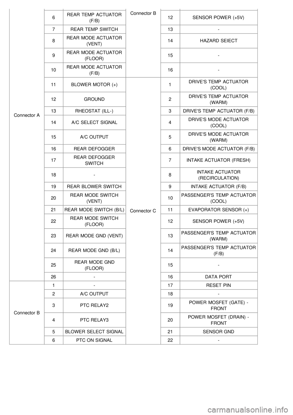
Connector AConnector B
6 REAR TEMP ACTUATOR
(F/B) 12
SENSOR POWER (+5V)
7 REAR TEMP SWITCH 13-
8 REAR MODE ACTUATOR
(VENT) 14
HAZARD SEIECT
9 REAR MODE ACTUATOR
(FLOOR) 15
-
10 REAR MODE ACTUATOR
(F/B) 16
-
11 BLOWER MOTOR (+)
Connector C1
DRIVE'S TEMP ACTUATOR
(COOL)
12 GROUND 2DRIVE'S TEMP ACTUATOR
(WARM)
13 RHEOSTAT (ILL- ) 3DRIVE'S TEMP ACTUATOR (F/B)
14 A/C SELECT SIGNAL 4DRIVE'S MODE ACTUATOR
(COOL)
15 A/C OUTPUT 5DRIVE'S MODE ACTUATOR
(WARM)
16 REAR DEFOGGER 6DRIVE'S MODE ACTUATOR (F/B)
17 REAR DEFOGGER
SWITCH 7
INTAKE ACTUATOR (FRESH)
18 - 8INTAKE ACTUATOR
(RECIRCULATION)
19 REAR BLOWER SWITCH 9INTAKE ACTUATOR (F/B)
20 REAR MODE SWITCH
(VENT) 10
PASSENGER'S TEMP ACTUATOR
(COOL)
21 REAR MODE SWITCH (B/L) 11EVAPORATOR SENSOR (+)
22 REAR MODE SWITCH
(FLOOR) 12
SENSOR POWER (+5V)
23 REAR MODE GND (VENT) 13PASSENGER'S TEMP ACTUATOR
(WARM)
24 REAR MODE GND (B/L) 14PASSENGER'S TEMP ACTUATOR
(F/B)
25 REAR MODE GND
(FLOOR) 15
-
26 - 16DATA PORT
Connector B 1
- 17RESET PIN
2 A/C OUTPUT 18-
3 PTC RELAY2 19POWER MOSFET (GATE) -
FRONT
4 PTC RELAY3 20POWER MOSFET (DRAIN) -
FRONT
5 BLOWER SELECT SIGNAL 21SENSOR GND
6 PTC ON SIGNAL 22-
Page 787 of 1575
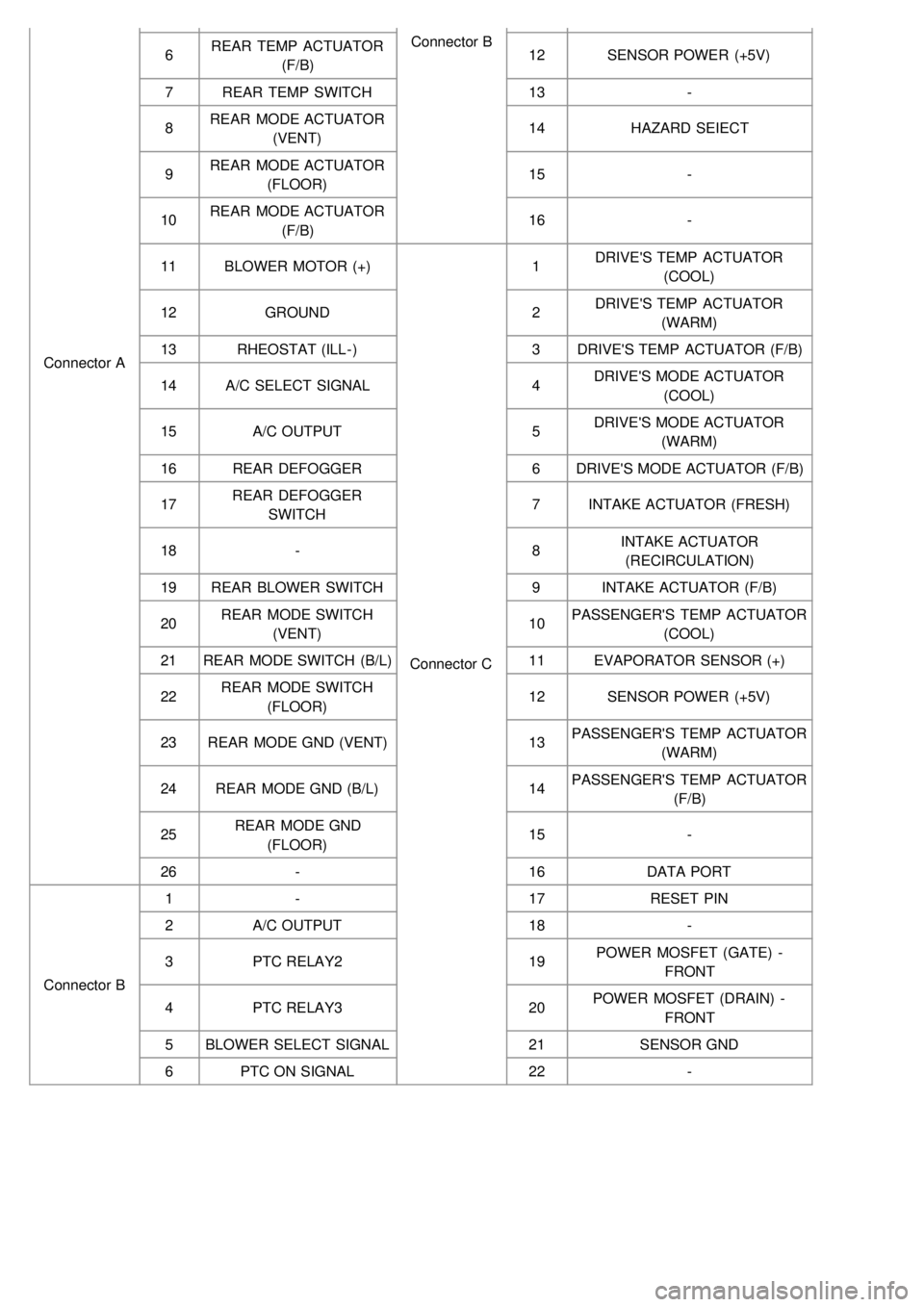
Connector AConnector B
6 REAR TEMP ACTUATOR
(F/B) 12
SENSOR POWER (+5V)
7 REAR TEMP SWITCH 13-
8 REAR MODE ACTUATOR
(VENT) 14
HAZARD SEIECT
9 REAR MODE ACTUATOR
(FLOOR) 15
-
10 REAR MODE ACTUATOR
(F/B) 16
-
11 BLOWER MOTOR (+)
Connector C1
DRIVE'S TEMP ACTUATOR
(COOL)
12 GROUND 2DRIVE'S TEMP ACTUATOR
(WARM)
13 RHEOSTAT (ILL- ) 3DRIVE'S TEMP ACTUATOR (F/B)
14 A/C SELECT SIGNAL 4DRIVE'S MODE ACTUATOR
(COOL)
15 A/C OUTPUT 5DRIVE'S MODE ACTUATOR
(WARM)
16 REAR DEFOGGER 6DRIVE'S MODE ACTUATOR (F/B)
17 REAR DEFOGGER
SWITCH 7
INTAKE ACTUATOR (FRESH)
18 - 8INTAKE ACTUATOR
(RECIRCULATION)
19 REAR BLOWER SWITCH 9INTAKE ACTUATOR (F/B)
20 REAR MODE SWITCH
(VENT) 10
PASSENGER'S TEMP ACTUATOR
(COOL)
21 REAR MODE SWITCH (B/L) 11EVAPORATOR SENSOR (+)
22 REAR MODE SWITCH
(FLOOR) 12
SENSOR POWER (+5V)
23 REAR MODE GND (VENT) 13PASSENGER'S TEMP ACTUATOR
(WARM)
24 REAR MODE GND (B/L) 14PASSENGER'S TEMP ACTUATOR
(F/B)
25 REAR MODE GND
(FLOOR) 15
-
26 - 16DATA PORT
Connector B 1
- 17RESET PIN
2 A/C OUTPUT 18-
3 PTC RELAY2 19POWER MOSFET (GATE) -
FRONT
4 PTC RELAY3 20POWER MOSFET (DRAIN) -
FRONT
5 BLOWER SELECT SIGNAL 21SENSOR GND
6 PTC ON SIGNAL 22-
Page 795 of 1575

2007 > 2.7L V6 GASOLINE >
General
The supplemental restraint system (SRS) is designed to supplement the seat belt to help reduce the risk or severity of
injury to the driver and passenger by activating and deploying the driver, passenger, side airbag and belt pretensioner
in certain frontal or side collisions.
The SRS (Airbag) consists of : a driver side airbag module located in the center of the steering wheel, which contains
the folded cushion and an inflator unit ; a passenger side airbag module located in the passenger side crash pad
contains the folded cushion assembled with inflator unit ; side airbag modules located in the driver and passenger seat
contain the folded cushion and an inflator unit ; curtain airbag modules located inside of the headliner which contains
folded cushions and inflator units. The impact sensing function of the SRSCM is carried out by electronic
accelerometer that continuously measure the vehicle's acceleration and delivers a corresponding signal through
amplifying and filtering circuitry to the microprocessor.
SRSCM (SRS Control Module)
SRSCM will detect front impact with front impact sensor, and side impact with side impact sensor, and determine
airbag module deployment.
1. DC/DC converter: DC/DC converter in power supply unit includes up/down transformer converter, and provide
ignition voltage for 2 front airbag ignition circuits and the internal operation voltage of the SRSCM. If the internal
operation voltage is below critical value setting, it will perform resetting.
2. Safety sensor: Safety sensor is located in airbag ignition circuit. Safety sensor will operate airbag circuit at any
deployment condition and release airbag circuit safely at normal driving condition. Safety sensor is a double contact
electro - mechanical switch that will close detecting deceleration above certain criteria.
3. Back up power supply: SRSCM has separate back up power supply, that will supply deployment energy instantly in
low voltage condition or upon power failure by front crash.
4. Self diagnosis: SRSCM will constantly monitor current SRS operation status and detect system failure while vehicle
power supply is on, system failure may be checked with trouble codes using scan tool. (Hi- Scan)
5. Airbag warning lamp on: Upon detecting error, the module will transmit signal to SRSCM indicator lamp located at
cluster. MIL lamp will indicate driver SRS error. Upon ignition key on, SRS lamp will turn on for about six seconds.
6. Trouble code registration: Upon error occurrence in system, SRSCM will store DTC corresponding to the error.
DTC can be cleared only by Hi - Scan. However, if an internal fault code is logged or if a crash is recorded the fault
clearing should not happen.
7. Self diagnostic connector: Data stored in SRSCM memory will be output to Hi - Scan or other external output
devices through connector located below driver side crash pad.
8. Once airbag is deployed, SRSCM should not be used again but replaced.
9. SRSCM will determine whether passenger put on seat belt by the signal from built- in switch in seat belt buckle, and
deploy front seat airbag at each set crash speed.
10. Side airbag deployment will be determined by SRSCM that will detect satellite sensor impact signal upon side
crash, irrespective to seat belt condition.
Page 1078 of 1575
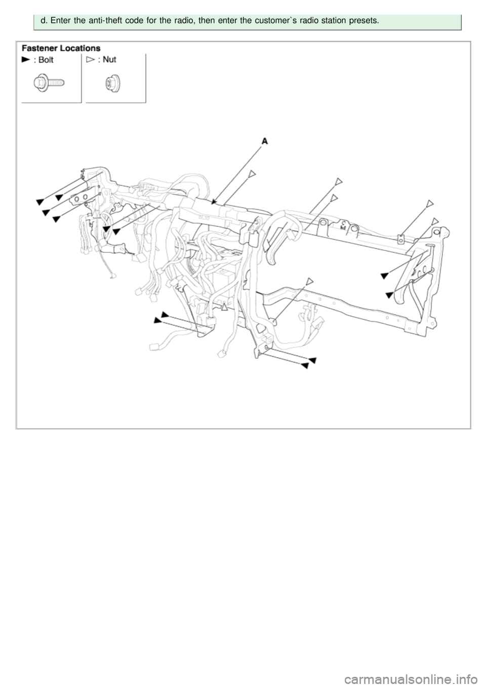
d.Enter the anti- theft code for the radio, then enter the customer`s radio station presets.
Page 1213 of 1575
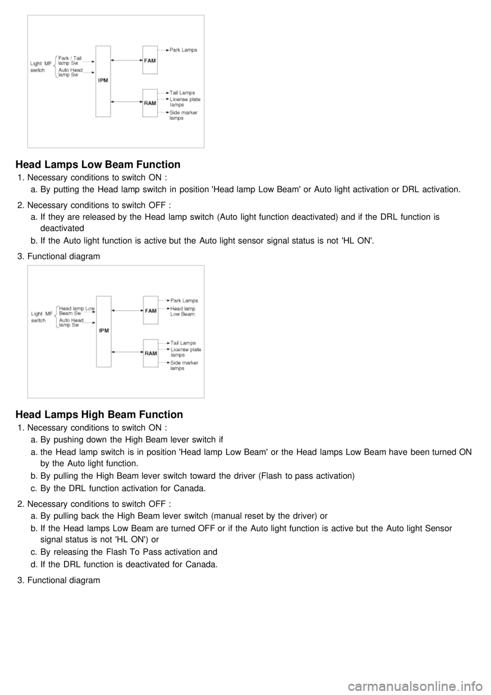
Head Lamps Low Beam Function
1.Necessary conditions to switch ON :
a. By putting the Head lamp switch in position 'Head lamp Low Beam' or Auto light activation or DRL activation.
2. Necessary conditions to switch OFF :
a. If they are released by the Head lamp switch (Auto light function deactivated) and if the DRL function is
deactivated
b. If the Auto light function is active but the Auto light sensor signal status is not 'HL ON'.
3. Functional diagram
Head Lamps High Beam Function
1.Necessary conditions to switch ON :
a. By pushing down the High Beam lever switch if
a. the Head lamp switch is in position 'Head lamp Low Beam' or the Head lamps Low Beam have been turned ON
by the Auto light function.
b. By pulling the High Beam lever switch toward the driver (Flash to pass activation)
c. By the DRL function activation for Canada.
2. Necessary conditions to switch OFF :
a. By pulling back the High Beam lever switch (manual reset by the driver) or
b. If the Head lamps Low Beam are turned OFF or if the Auto light function is active but the Auto light Sensor
signal status is not 'HL ON') or
c. By releasing the Flash To Pass activation and
d. If the DRL function is deactivated for Canada.
3. Functional diagram
Page 1217 of 1575
activation.
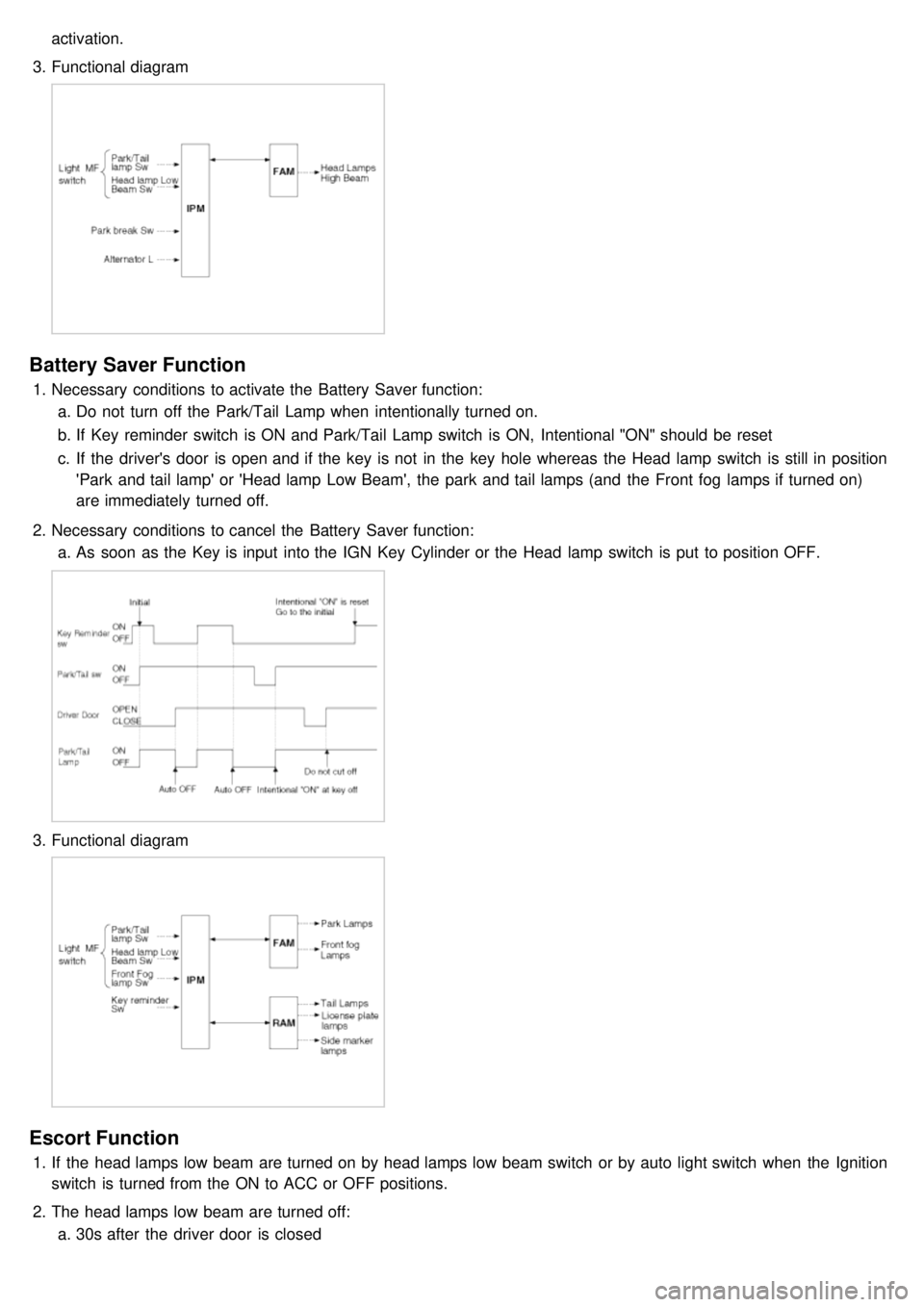
3. Functional diagram
Battery Saver Function
1.Necessary conditions to activate the Battery Saver function:
a. Do not turn off the Park/Tail Lamp when intentionally turned on.
b. If Key reminder switch is ON and Park/Tail Lamp switch is ON, Intentional "ON" should be reset
c. If the driver's door is open and if the key is not in the key hole whereas the Head lamp switch is still in position
'Park and tail lamp' or 'Head lamp Low Beam', the park and tail lamps (and the Front fog lamps if turned on)
are immediately turned off.
2. Necessary conditions to cancel the Battery Saver function:
a. As soon as the Key is input into the IGN Key Cylinder or the Head lamp switch is put to position OFF.
3.Functional diagram
Escort Function
1.If the head lamps low beam are turned on by head lamps low beam switch or by auto light switch when the Ignition
switch is turned from the ON to ACC or OFF positions.
2. The head lamps low beam are turned off:
a. 30s after the driver door is closed
Page 1259 of 1575
2007 > 2.7L V6 GASOLINE >
DESCRIPTION
An optimal seat position set by a driver can be memorized in P/seat unit by memory SW and position SW, which
enables restoration of seat position set by the driver despite seat adjustments.
Furthermore, data is transmitted between P/seat and IPM, DDM, ADM, RAM, FAM, CLUSTER through CAN BUS.
Seat position presets cannot be recalled while driving. An emergency stop function is provided; additional functions are
described below.
1. It conducts manual operation of seat by CAN BUS data transmitted by DDM as well as that of adjustable pedal by
CAN BUS data transmitted by IPM received when operating SW manually.
2. Manual SW behavior when communication stops (back- up behavior)
a. Slide front/rear
b. Recline front/rear
c. Position control of slide motor is possible by manual SW even in case of congestion in CPU or removal of a
fuse for P/seat unit B.
3. 2 memory locations are provided for storing seat, outside mirror, and adjustable pedal presets.
4. The driver seat can be set to slide rearward when the ignition key is removed, and forward when the key is
inserted.
5. 2 additional presets for seat, mirror, and adjustable pedal position can be stored with the RKE transmitter.
OPERATION
MANUAL OPERATION
Manual operation of the driver seat and adjustable pedals is possible provided the transaxle is in 'P' range and the
vehicle speed is 0 MPH. Operation of the manual controls overrides any automatic operation commanded via CAN.
MEMORY OPERATION
1. Pressing the 'M' button on the control panel will place the system into memory storage mode and will result in a
single pulse from the output buzzer.
2. If one of the memory location buttons is pressed and held within 5 seconds of pressing the 'M' button, the output
buzzer will pulse twice to indicate successful storage of seat, mirror, and adjustable pedal positions.
3. The ignition switch must be in the RUN or START position, the vehicle speed must be 0 MPH, and the transaxle
must be in 'P' range to store memory presets.
4. Pressing the 'M' button while recalling a stored preset will halt the preset recall operation.
5. Memory will be cleared if battery is removed.
MEMORY REPLAY OPERATION
1.Pressing one of the memory location buttons will result in the driver seat, outside mirrors, and adjustable pedals
being positioned based on the stored preset data.
2. The ignition switch must be in the RUN position, the transaxle must be in 'P' range, the vehicle speed must be 0
MPH, and the manual functions must not be in operation to recall stored presets.
3. Others
a. Play operation not recorded in the position switch will not be conducted and there will be no buzzer output.
b. If other data is received during preset recall operation, the most recent preset recall signal will take
precedence.
c. If engine is started during preset recall operation, halt preset recall operation, and resume it toward target
position 100ms after Ignition switch is returned to "RUN". However, if the START state lasts over 5 sec., it will
not resume even after returning to RUN.
d. If preset recall order is received during engine start, preset recall operation is inhibited.
e. If input from manual switch for seat and adjust pedal occurs during preset recall operation of seat and adjust
pedal, halt all their preset recall operations.
f. If an error occurs during manual operation of seat and adjust pedal, delete Memory.