Page 5400 of 6020
8A-462 ELECTRICAL-BODY AND CHASSIS
TROUBLESHOOTING
CIGARETTE LIGHTER
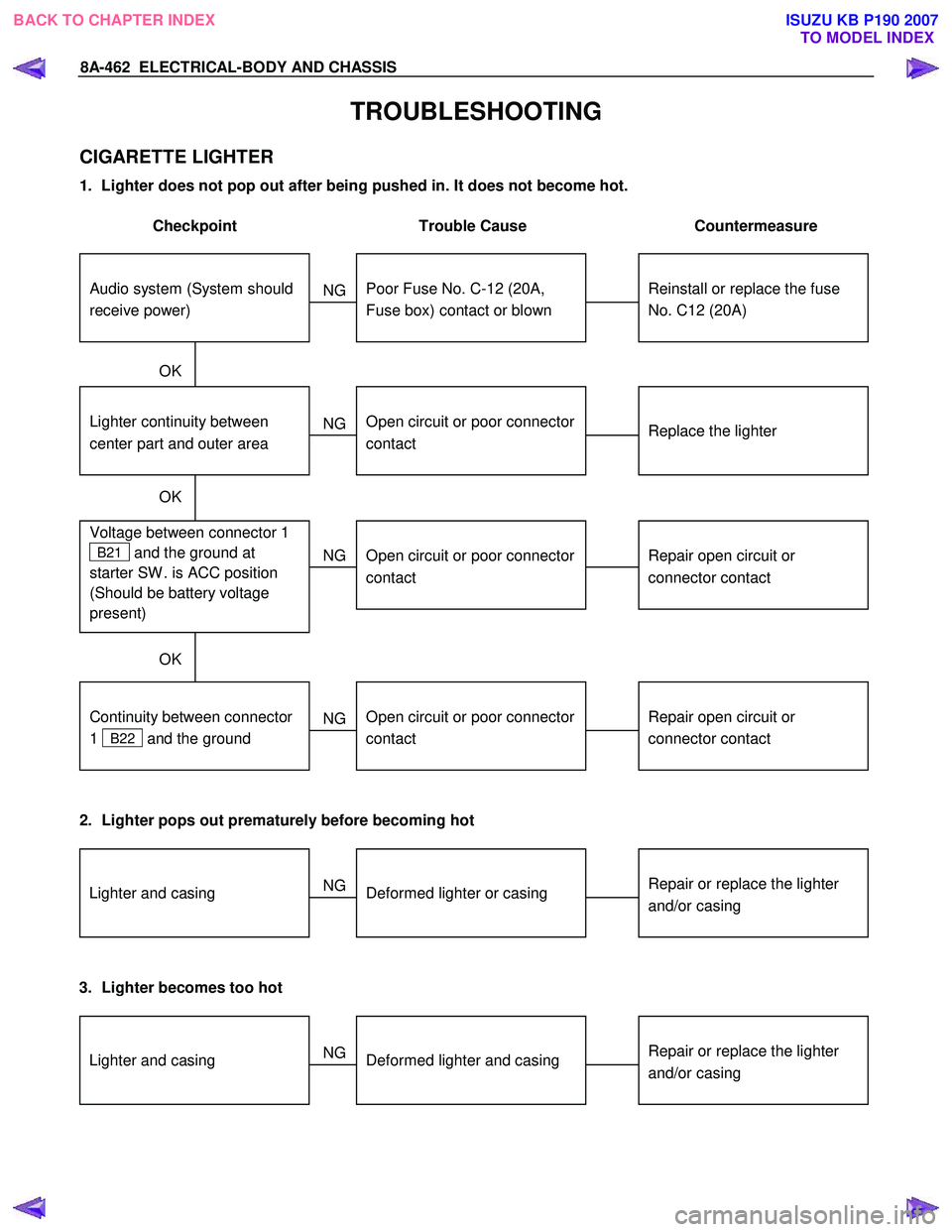
1. Lighter does not pop out after being pushed in. It does not become hot.
Checkpoint Trouble Cause Countermeasure
Reinstall or replace the fuse
No. C12 (20A)
Poor Fuse No. C-12 (20A,
Fuse box) contact or blown
NG
Replace the lighter
Lighter continuity between
center part and outer area
Open circuit or poor connector
contact
Repair open circuit or
connector contact
Voltage between connector 1
B21 and the ground at
starter SW . is ACC position
(Should be battery voltage
present)
Open circuit or poor connector
contact
NG
NG
OK
OK
OK
Audio system (System should
receive power)
Repair open circuit or
connector contact
Open circuit or poor connector
contact
NG
Continuity between connector
1
B22 and the ground
2. Lighter pops out prematurely before becoming hot
Repair or replace the lighter
and/or casingDeformed lighter or casing
NGLighter and casing
3. Lighter becomes too hot
Repair or replace the lighter
and/or casingDeformed lighter and casing
NGLighter and casing
BACK TO CHAPTER INDEX
TO MODEL INDEXISUZU KB P190 2007
Page 5401 of 6020
ELECTRICAL-BODY AND CHASSIS 8A-463
REMOVAL AND INSTALLATION
AUDIO
Refer to Section 9 “ACCESSORIES” for details.
RTW 780SH001801
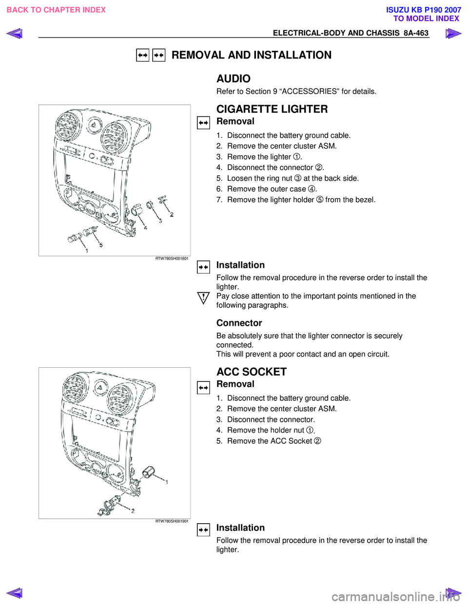
CIGARETTE LIGHTER
Removal
1. Disconnect the battery ground cable.
2. Remove the center cluster ASM.
3. Remove the lighter
1.
4. Disconnect the connector
2.
5. Loosen the ring nut
3 at the back side.
6. Remove the outer case
4.
7. Remove the lighter holder
5 from the bezel.
Installation
Follow the removal procedure in the reverse order to install the
lighter.
Pay close attention to the important points mentioned in the
following paragraphs.
Connector
Be absolutely sure that the lighter connector is securely
connected.
This will prevent a poor contact and an open circuit.
RTW 780SH001901
ACC SOCKET
Removal
1. Disconnect the battery ground cable.
2. Remove the center cluster ASM.
3. Disconnect the connector.
4. Remove the holder nut
1.
5. Remove the ACC Socket
2
Installation
Follow the removal procedure in the reverse order to install the
lighter.
BACK TO CHAPTER INDEX TO MODEL INDEXISUZU KB P190 2007
Page 5411 of 6020
ELECTRICAL-BODY AND CHASSIS 8A-473
DOOR MIRROR CONTROL SWITCH
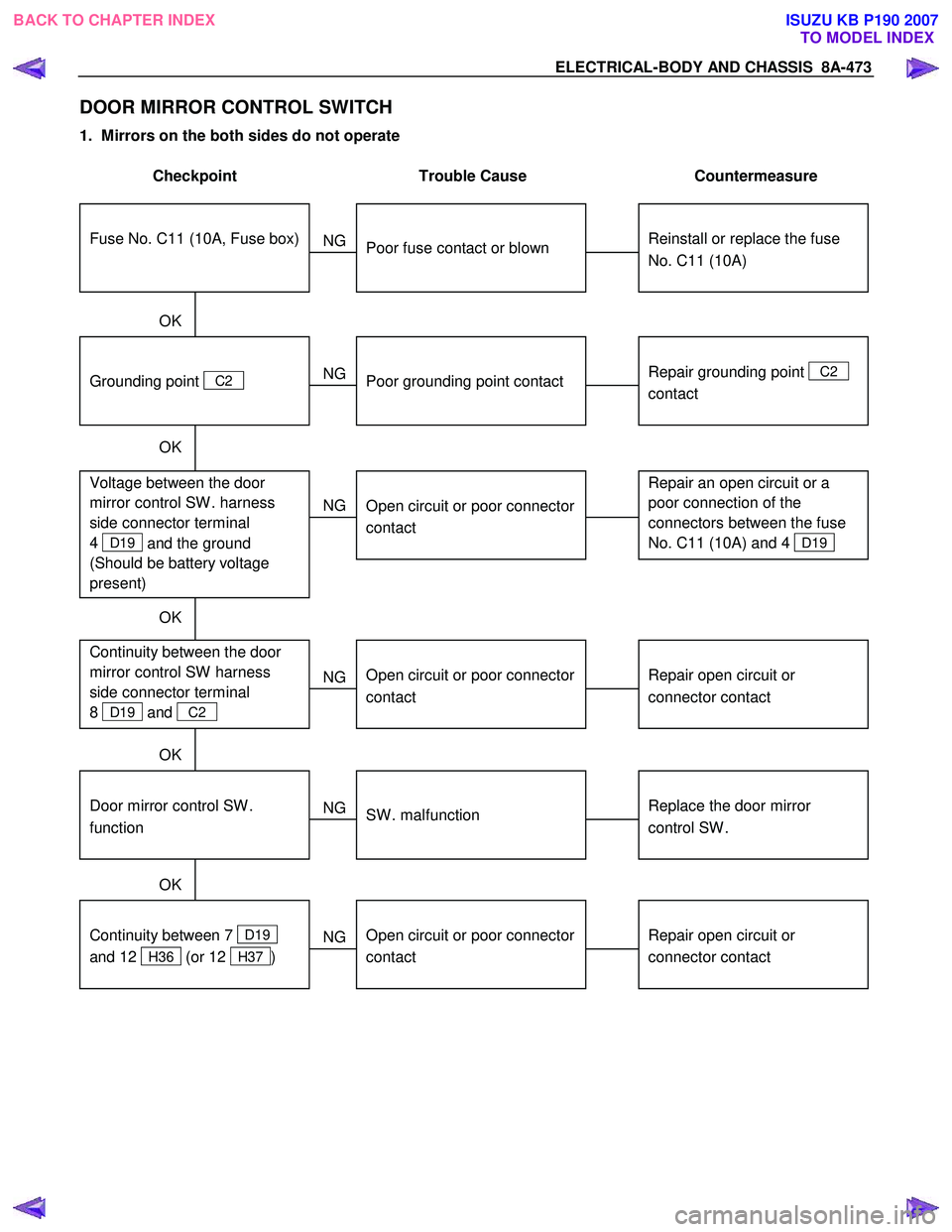
1. Mirrors on the both sides do not operate
Checkpoint Trouble Cause Countermeasure
Reinstall or replace the fuse
No. C11 (10A)
Poor fuse contact or blown
NG
Repair grounding point
C2
contact
Grounding point
C2
Poor grounding point contact
Repair an open circuit or a
poor connection of the
connectors between the fuse
No. C11 (10A) and 4
D19
Voltage between the door
mirror control SW . harness
side connector terminal
4
D19 and the ground
(Should be battery voltage
present)
Open circuit or poor connector
contact
NG
NG
OK
OK
OK
Fuse No. C11 (10A, Fuse box)
Repair open circuit or
connector contact
Open circuit or poor connector
contact
NG Continuity between the door
mirror control SW harness
side connector terminal
8
D19 and C2
Replace the door mirror
control SW .
Door mirror control SW .
function
SW . malfunction
NG
OK
Repair open circuit or
connector contact
Continuity between 7
D19
and 12
H36 (or 12 H37 )
Open circuit or poor connector
contact
NG
OK
BACK TO CHAPTER INDEX TO MODEL INDEXISUZU KB P190 2007
Page 5414 of 6020
8A-476 ELECTRICAL-BODY AND CHASSIS
REMOVAL AND INSTALLATION
DOOR MIRROR CONTROL SWITCH
Removal
1. Disconnect the battery ground cable.
2. Door trim pad Assembly • Refer to section 10 “BODY” for door trim pad assembl
y
removal steps.
3. Door Mirror Control Switch
Remove the power window switch bezel. • Remove the screw.
• Disconnect the switch connector.
• To remove the switch panel assembly.
Installation
To install, follow the removal steps in the reverse order.
DOOR MIRROR
Removal and Installation
Refer to the DOOR MIRROR in section 10 “BODY”.
BACK TO CHAPTER INDEX TO MODEL INDEXISUZU KB P190 2007
Page 5416 of 6020
8A-478 ELECTRICAL-BODY AND CHASSIS
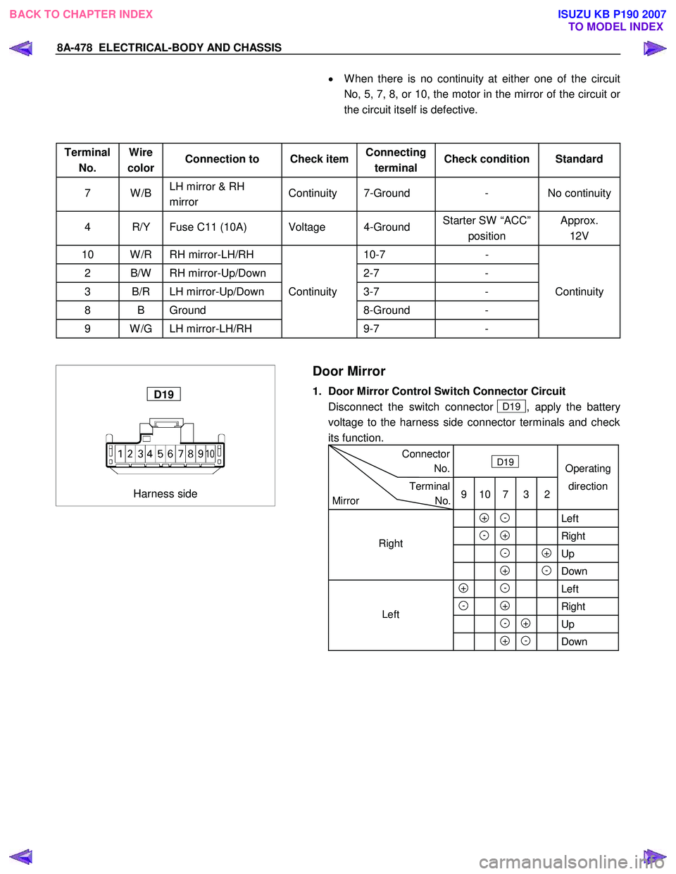
• W hen there is no continuity at either one of the circuit
No, 5, 7, 8, or 10, the motor in the mirror of the circuit o
r
the circuit itself is defective.
Terminal No. Wire
color Connection to Check item
Connecting
terminal Check condition Standard
7 W /B
LH mirror & RH
mirror Continuity 7-Ground - No continuity
4 R/Y Fuse C11 (10A) Voltage 4-Ground
Starter SW “ACC”
position Approx.
12V
10 W /R RH mirror-LH/RH 10-7 -
2 B/W RH mirror-Up/Down 2-7 -
3 B/R LH mirror-Up/Down Continuity 3-7 - Continuity
8 B Ground 8-Ground -
9 W /G LH mirror-LH/RH 9-7 -
Harness side
D19
Door Mirror
1. Door Mirror Control Switch Connector Circuit
Disconnect the switch connector
D19 , apply the battery
voltage to the harness side connector terminals and check
its function.
Connector
No. D19
Operating
Terminal
Mirror No. 9 10 7 3 2direction
+ - Left
- + Right
- +Up
+ -Down
+ - Left
- + Right
- + Up
+ - Down
Left
Right
BACK TO CHAPTER INDEX
TO MODEL INDEXISUZU KB P190 2007
Page 5424 of 6020
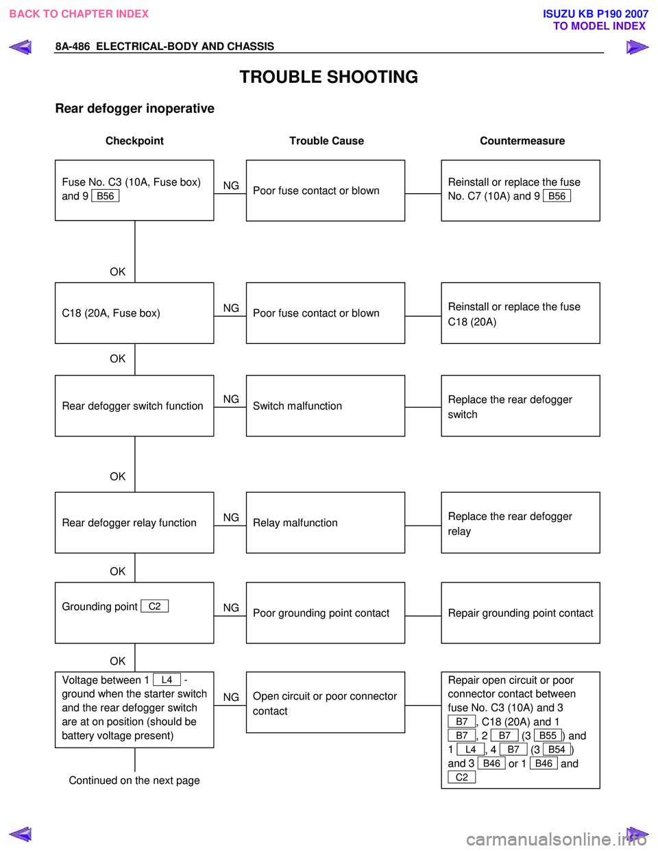
8A-486 ELECTRICAL-BODY AND CHASSIS
TROUBLE SHOOTING
Rear defogger inoperative
Checkpoint Trouble Cause Countermeasure
Reinstall or replace the fuse
No. C7 (10A) and 9
B56
Poor fuse contact or blown
NG
Reinstall or replace the fuse
C18 (20A)
C18 (20A, Fuse box)
Poor fuse contact or blown
Replace the rear defogger
switch
Rear defogger switch function
Switch malfunction
NG
NG
OK
OK
OK
Fuse No. C3 (10A, Fuse box)
and 9
B56
Replace the rear defogger
relay
Relay malfunction
NG
Continued on the next page
Rear defogger relay function
Repair grounding point contact
Grounding point
C2
Poor grounding point contact
NG
OK
Repair open circuit or poor
connector contact between
fuse No. C3 (10A) and 3
B7 , C18 (20A) and 1
B7 , 2 B7 (3 B55) and
1
L4 , 4 B7 (3 B54)
and 3
B46 or 1 B46 and
C2
Voltage between 1 L4 -
ground when the starter switch
and the rear defogger switch
are at on position (should be
battery voltage present)
Open circuit or poor connector
contact
NG
OK
BACK TO CHAPTER INDEX
TO MODEL INDEXISUZU KB P190 2007
Page 5427 of 6020
ELECTRICAL-BODY AND CHASSIS 8A-489
INSPECTION AND REPAIR
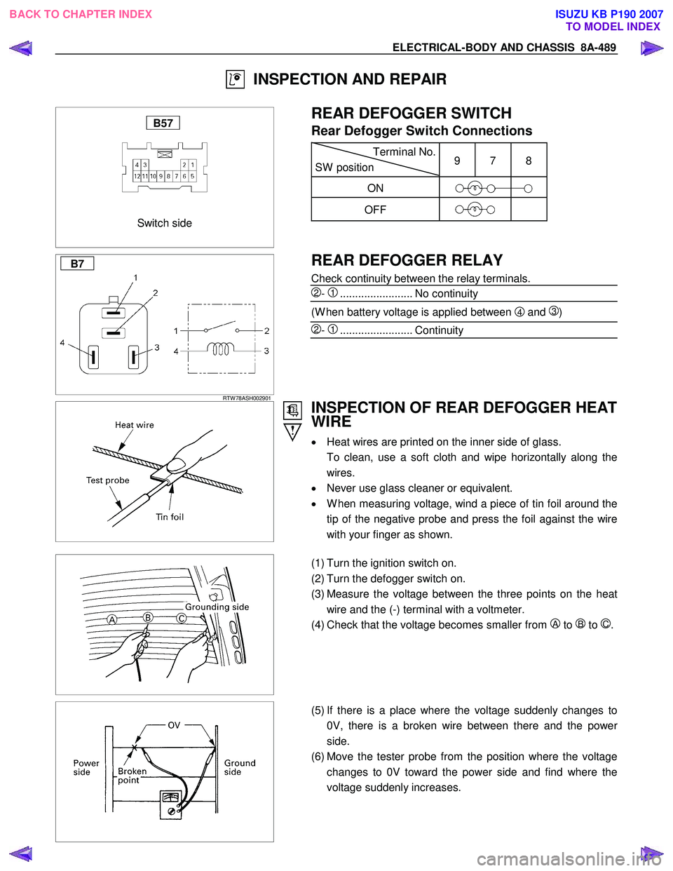
Switch side
B57
REAR DEFOGGER SWITCH
Rear Defogger Switch Connections
Terminal No.
SW position 9 7 8
ON
OFF
B7
RTW 78ASH002901
REAR DEFOGGER RELAY
Check continuity between the relay terminals.
2- 1........................ No continuity
(W hen battery voltage is applied between 4 and 3)
2- 1........................ Continuity
INSPECTION OF REAR DEFOGGER HEAT
WIRE
• Heat wires are printed on the inner side of glass.
To clean, use a soft cloth and wipe horizontally along the wires.
• Never use glass cleaner or equivalent.
• W hen measuring voltage, wind a piece of tin foil around the
tip of the negative probe and press the foil against the wire
with your finger as shown.
(1) Turn the ignition switch on.
(2) Turn the defogger switch on.
(3) Measure the voltage between the three points on the heat wire and the (-) terminal with a voltmeter.
(4) Check that the voltage becomes smaller from
A to B to C.
(5) If there is a place where the voltage suddenly changes to
0V, there is a broken wire between there and the powe
r
side.
(6) Move the tester probe from the position where the voltage changes to 0V toward the power side and find where the
voltage suddenly increases.
BACK TO CHAPTER INDEX TO MODEL INDEXISUZU KB P190 2007
Page 5476 of 6020
8A-538 ELECTRICAL-BODY AND CHASSIS
TROUBLESHOOTING
Diagnostic procedure
•
Check the operation "Lock / unlock" by using
transmitter (remote key) on the vehicle.
• Check the operation "ON / OFF" for Driver side
door SW on the vehicle.
• Perform the Keyless entry System Check.
Diagnostic Aids
An intermittent may be caused by the following:
• Poor connections.
• Miss routed harness.
• Rubbed through wire insulation.
• Broken wire inside the insulation.
Check for the following conditions:
• Poor connection at keyless entry control unit-
Inspect harness connectors for backed out
terminals, improper mating, broken locks,
improperly formed or damaged terminals, and poo
r
terminal to wire connection.
• Damaged harness-Inspect the wiring harness fo
r
damage.
Check the Electro-Magnetic Interference (EMI)
• Location of vehicle check
Move the vehicle to a new location and perform
the check again.
• Non-OEM Parts.
Switch is “OFF” or remove the Non-OEM parts and
perform the check again.
• Other
Remove the accessory and another key from key.
Check the other items.
• Battery voltage is low.
• Keyless entry programming functions.
• Registration for security code.
• Ignition switch operation.
• Meter system is malfunction.
Check the operation
Check the operation "Lock / unlock" by using
transmitter (remote key) on the vehicle.
Notice
If so equipped the Anti Theft, Refer to ANTI
THEFT SYSTEM in 11B Section.
BACK TO CHAPTER INDEX TO MODEL INDEXISUZU KB P190 2007