2007 ISUZU KB P190 BATTERY
[x] Cancel search: BATTERYPage 5574 of 6020
8B-2 CRUISE CONTROL SYSTEM
General Description
The cruise control keeps the vehicle running at a fixed speed until a signal canceling this fixed speed is received.
W hen the main switch “AUTO CRUISE” is turned on with the vehicle in the running mode, the battery voltage is
applied to the control unit (Engine control module). W hen a signal from the control unit while the vehicle is in this
state, the cruise control actuator is activated to operate the system. Also, while the system is operating, the cruise
control set indicator light in the meter assembly lights up.
RTU7Z0SH019601
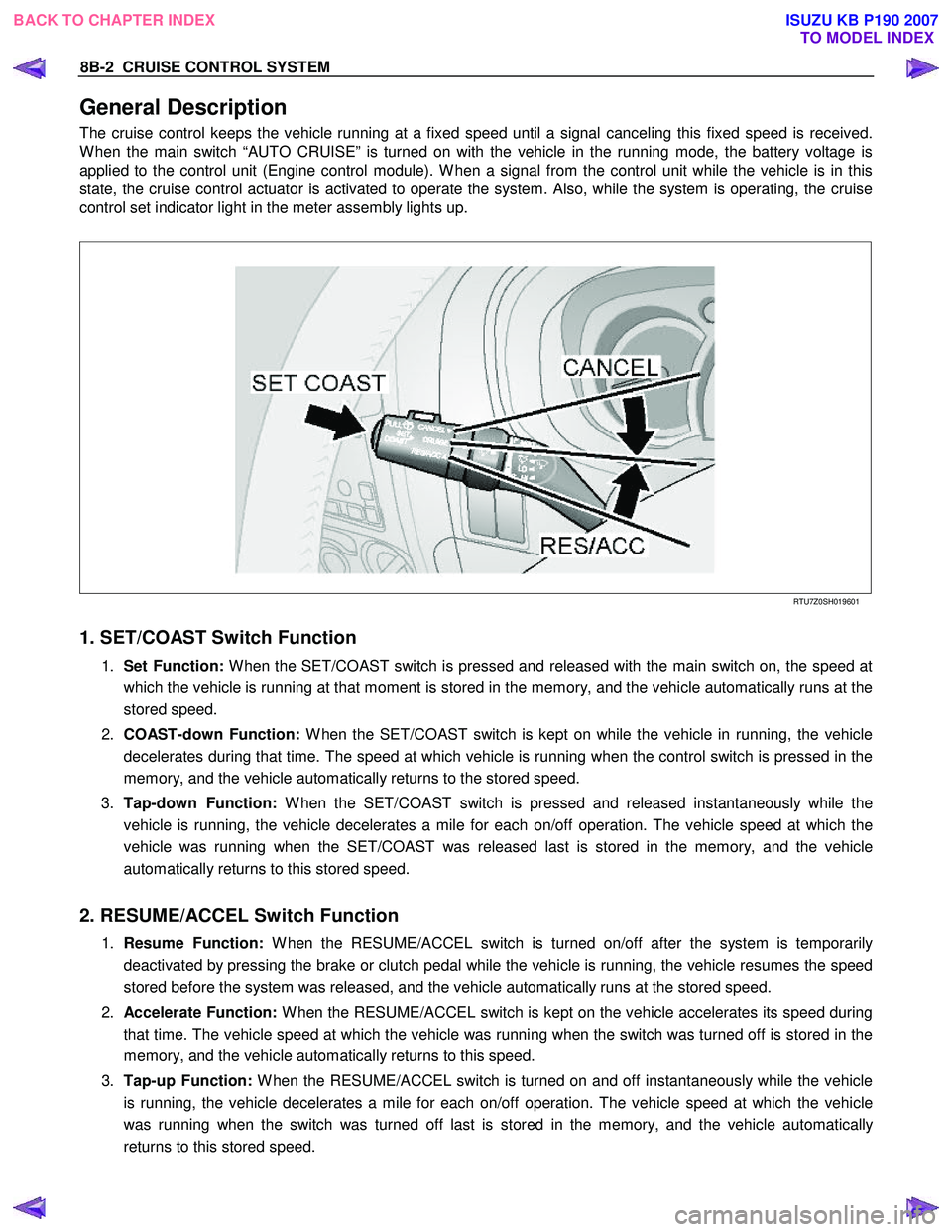
1. SET/COAST Switch Function
1. Set Function: W hen the SET/COAST switch is pressed and released with the main switch on, the speed at
which the vehicle is running at that moment is stored in the memory, and the vehicle automatically runs at the
stored speed.
2. COAST-down Function: W hen the SET/COAST switch is kept on while the vehicle in running, the vehicle
decelerates during that time. The speed at which vehicle is running when the control switch is pressed in the
memory, and the vehicle automatically returns to the stored speed.
3. Tap-down Function: W hen the SET/COAST switch is pressed and released instantaneously while the
vehicle is running, the vehicle decelerates a mile for each on/off operation. The vehicle speed at which the
vehicle was running when the SET/COAST was released last is stored in the memory, and the vehicle
automatically returns to this stored speed.
2. RESUME/ACCEL Switch Function
1. Resume Function: W hen the RESUME/ACCEL switch is turned on/off after the system is temporarily
deactivated by pressing the brake or clutch pedal while the vehicle is running, the vehicle resumes the speed
stored before the system was released, and the vehicle automatically runs at the stored speed.
2. Accelerate Function: W hen the RESUME/ACCEL switch is kept on the vehicle accelerates its speed during
that time. The vehicle speed at which the vehicle was running when the switch was turned off is stored in the
memory, and the vehicle automatically returns to this speed.
3. Tap-up Function: W hen the RESUME/ACCEL switch is turned on and off instantaneously while the vehicle
is running, the vehicle decelerates a mile for each on/off operation. The vehicle speed at which the vehicle
was running when the switch was turned off last is stored in the memory, and the vehicle automatically
returns to this stored speed.
BACK TO CHAPTER INDEX TO MODEL INDEXISUZU KB P190 2007
Page 5576 of 6020
8B-4 CRUISE CONTROL SYSTEM
Brake Switch
RTW 3A0MH000101
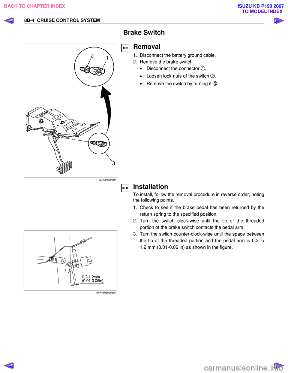
Removal
1. Disconnect the battery ground cable.
2. Remove the brake switch.
• Disconnect the connector
1.
• Loosen lock nuts of the switch
2.
• Remove the switch by turning it
3 .
Installation
To install, follow the removal procedure in reverse order, noting
the following points.
1. Check to see if the brake pedal has been returned by the
return spring to the specified position.
2. Turn the switch clock-wise until the tip of the threaded
portion of the brake switch contacts the pedal arm.
RTW 780SH003201
3. Turn the switch counter-clock-wise until the space between
the tip of the threaded portion and the pedal arm is 0.2 to
1.2 mm (0.01-0.06 in) as shown in the figure.
BACK TO CHAPTER INDEX
TO MODEL INDEXISUZU KB P190 2007
Page 5578 of 6020

8B-6 CRUISE CONTROL SYSTEM
Cruise Control Main Switch
Removal
1. Disconnect the battery ground cable.
RTW 78ASH001801
2. Remove the side ventilation grille 1.
RTW 78ASH002301
3. Disconnect the switch connector and push the lock from the
backside of the side ventilation grille to remove the cruise
control main switch.
Installation
To install, follow the removal procedure in reverse order, noting
the following point.
1. Push in the switch with your fingers until it locks securely.
Cruise Control Switch (Combination Switch)
Removal and Installation
Refer to the Lighting Switch (Combination Switch) removal and
installation procedure of Lighting in Body and Chassis section.
BACK TO CHAPTER INDEX TO MODEL INDEXISUZU KB P190 2007
Page 5595 of 6020
Cruise Control – HFV6 Page 8C–17
Step Action Yes No
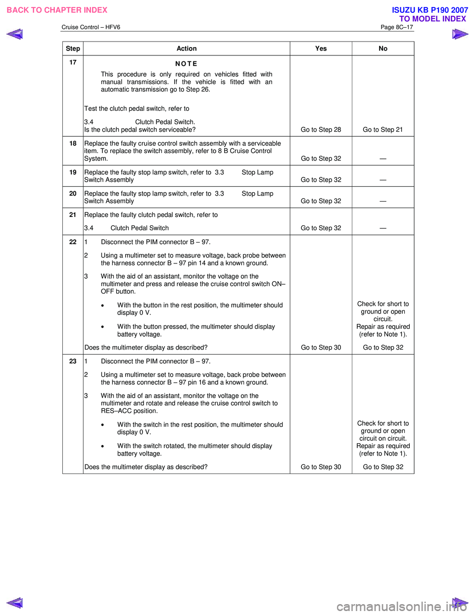
17
NOTE
This procedure is only required on vehicles fitted with
manual transmissions. If the vehicle is fitted with an
automatic transmission go to Step 26.
Test the clutch pedal switch, refer to
3.4 Clutch Pedal Switch.
Is the clutch pedal switch serviceable? Go to Step 28 Go to Step 21
18 Replace the faulty cruise control switch assembly with a serviceable
item. To replace the switch assembly, refer to 8 B Cruise Control
System. Go to Step 32 —
19 Replace the faulty stop lamp switch, refer to 3.3 Stop Lamp
Switch Assembly Go to Step 32 —
20 Replace the faulty stop lamp switch, refer to 3.3 Stop Lamp
Switch Assembly Go to Step 32 —
21
Replace the faulty clutch pedal switch, refer to
3.4 Clutch Pedal Switch Go to Step 32 —
22 1 Disconnect the PIM connector B – 97.
2 Using a multimeter set to measure voltage, back probe between the harness connector B – 97 pin 14 and a known ground.
3 W ith the aid of an assistant, monitor the voltage on the multimeter and press and release the cruise control switch ON–
OFF button.
• W ith the button in the rest position, the multimeter should
display 0 V.
• W ith the button pressed, the multimeter should display
battery voltage.
Does the multimeter display as described? Go to Step 30 Check for short to
ground or open circuit.
Repair as required
(refer to Note 1).
Go to Step 32
23 1 Disconnect the PIM connector B – 97.
2 Using a multimeter set to measure voltage, back probe between the harness connector B – 97 pin 16 and a known ground.
3 With the aid of an assistant, monitor the voltage on the multimeter and rotate and release the cruise control switch to
RES–ACC position.
• With the switch in the rest position, the multimeter should
display 0 V.
• With the switch rotated, the multimeter should display
battery voltage.
Does the multimeter display as described? Go to Step 30 Check for short to
ground or open
circuit on circuit.
Repair as required
(refer to Note 1).
Go to Step 32
BACK TO CHAPTER INDEX TO MODEL INDEXISUZU KB P190 2007
Page 5596 of 6020
Cruise Control – HFV6 Page 8C–18
Step Action Yes No
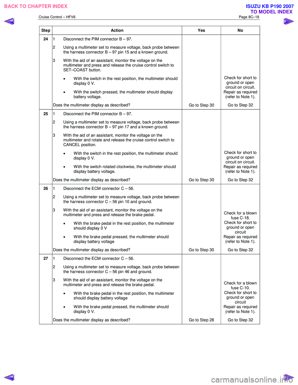
24 1 Disconnect the PIM connector B – 97.
2 Using a multimeter set to measure voltage, back probe between the harness connector B – 97 pin 15 and a known ground.
3 With the aid of an assistant, monitor the voltage on the multimeter and press and release the cruise control switch to
SET–COAST button.
• With the switch in the rest position, the multimeter should
display 0 V.
• With the switch pressed, the multimeter should display
battery voltage.
Does the multimeter display as described? Go to Step 30 Check for short to
ground or open
circuit on circuit.
Repair as required (refer to Note 1).
Go to Step 32
25 1 Disconnect the PIM connector B – 97.
2 Using a multimeter set to measure voltage, back probe between the harness connector B – 97 pin 17 and a known ground.
3 W ith the aid of an assistant, monitor the voltage on the multimeter and rotate and release the cruise control switch to
CANCEL position.
• With the switch in the rest position, the multimeter should
display 0 V.
• W ith the switch rotated clockwise, the multimeter should
display battery voltage.
Does the multimeter display as described? Go to Step 30 Check for short to
ground or open
circuit on circuit.
Repair as required (refer to Note 1).
Go to Step 32
26 1 Disconnect the ECM connector C – 56.
2 Using a multimeter set to measure voltage, back probe between the harness connector C – 56 pin 10 and ground.
3 With the aid of an assistant, monitor the voltage on the multimeter and press and release the brake pedal.
• W ith the brake pedal in the rest position, the multimeter
should display 0 V
• W ith the brake pedal pressed, the multimeter should
display battery voltage
Does the multimeter display as described? Go to Step 30 Check for a blown
fuse C-18.
Check for short to
ground or open circuit
Repair as required (refer to Note 1).
Go to Step 32
27 1 Disconnect the ECM connector C – 56.
2 Using a multimeter set to measure voltage, back probe between the harness connector C – 56 pin 46 and ground.
3 With the aid of an assistant, monitor the voltage on the multimeter and press and release the brake pedal.
• W ith the brake pedal in the rest position, the multimeter
should display battery voltage
• W ith the brake pedal pressed, the multimeter should
display 0 V.
Does the multimeter display as described? Go to Step 28 Check for a blown
fuse C-10.
Check for short to ground or open
circuit
Repair as required (refer to Note 1).
Go to Step 32
BACK TO CHAPTER INDEX TO MODEL INDEXISUZU KB P190 2007
Page 5597 of 6020
Cruise Control – HFV6 Page 8C–19
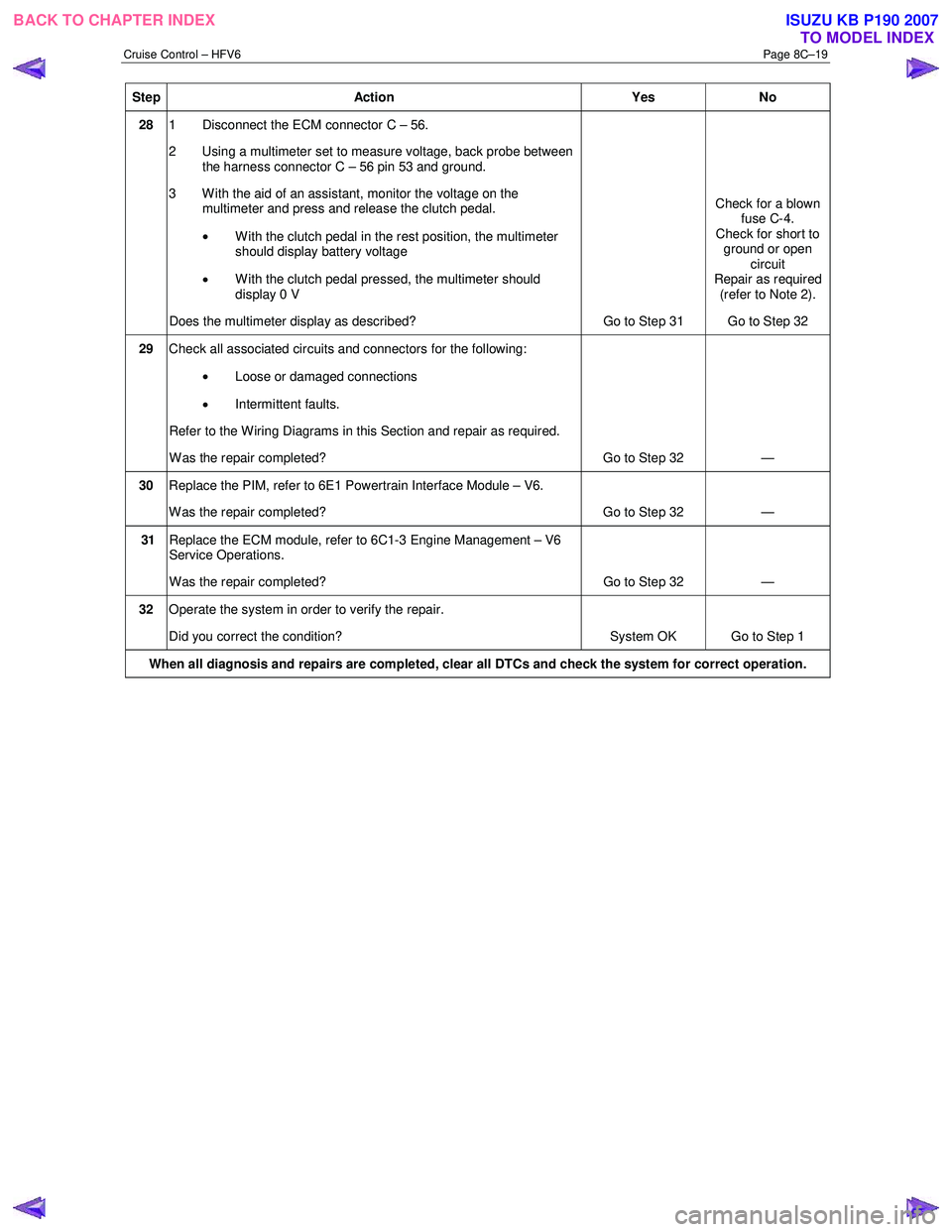
Step Action Yes No
28 1 Disconnect the ECM connector C – 56.
2 Using a multimeter set to measure voltage, back probe between the harness connector C – 56 pin 53 and ground.
3 W ith the aid of an assistant, monitor the voltage on the multimeter and press and release the clutch pedal.
• With the clutch pedal in the rest position, the multimeter
should display battery voltage
• W ith the clutch pedal pressed, the multimeter should
display 0 V
Does the multimeter display as described? Go to Step 31 Check for a blown
fuse C-4.
Check for short to ground or open circuit
Repair as required (refer to Note 2).
Go to Step 32
29 Check all associated circuits and connectors for the following:
• Loose or damaged connections
• Intermittent faults.
Refer to the Wiring Diagrams in this Section and repair as required.
W as the repair completed? Go to Step 32 —
30 Replace the PIM, refer to 6E1 Powertrain Interface Module – V6.
W as the repair completed? Go to Step 32 —
31 Replace the ECM module, refer to 6C1-3 Engine Management – V6
Service Operations.
W as the repair completed? Go to Step 32 —
32 Operate the system in order to verify the repair.
Did you correct the condition? System OK Go to Step 1
When all diagnosis and repairs are completed, clear all DTCs and check the system for correct operation.
BACK TO CHAPTER INDEX
TO MODEL INDEXISUZU KB P190 2007
Page 5628 of 6020
ACCESSORIES 9-23
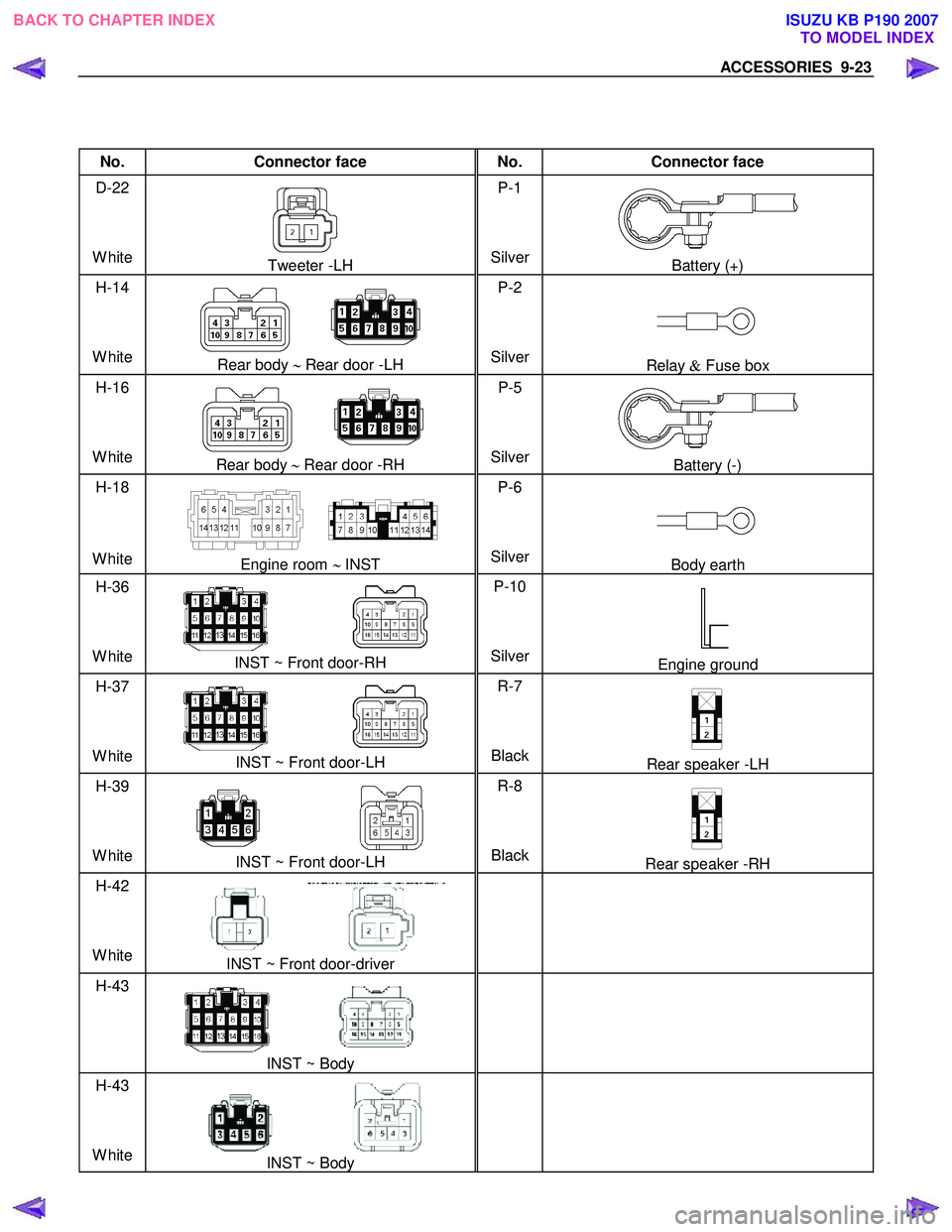
No. Connector face No. Connector face
D-22
White
Tweeter -LH P-1
SilverBattery (+)
H-14
White
Rear body ∼ Rear door -LH P-2
SilverRelay & Fuse box
H-16
White
Rear body ∼ Rear door -RH P-5
SilverBattery (-)
H-18
White
Engine room ∼ INST P-6
SilverBody earth
H-36
White
INST ~ Front door-RH P-10
SilverEngine ground
H-37
White
INST ~ Front door-LH R-7
BlackRear speaker -LH
H-39
White
INST ~ Front door-LH R-8
BlackRear speaker -RH
H-42
White
INST ~ Front door-driver
H-43
INST ~ Body
H-43
White
INST ~ Body
BACK TO CHAPTER INDEX TO MODEL INDEXISUZU KB P190 2007
Page 5651 of 6020
9A-16 SUPPLEMENTAL RESTRAINT SYSTEM
RTW 79ASH000201
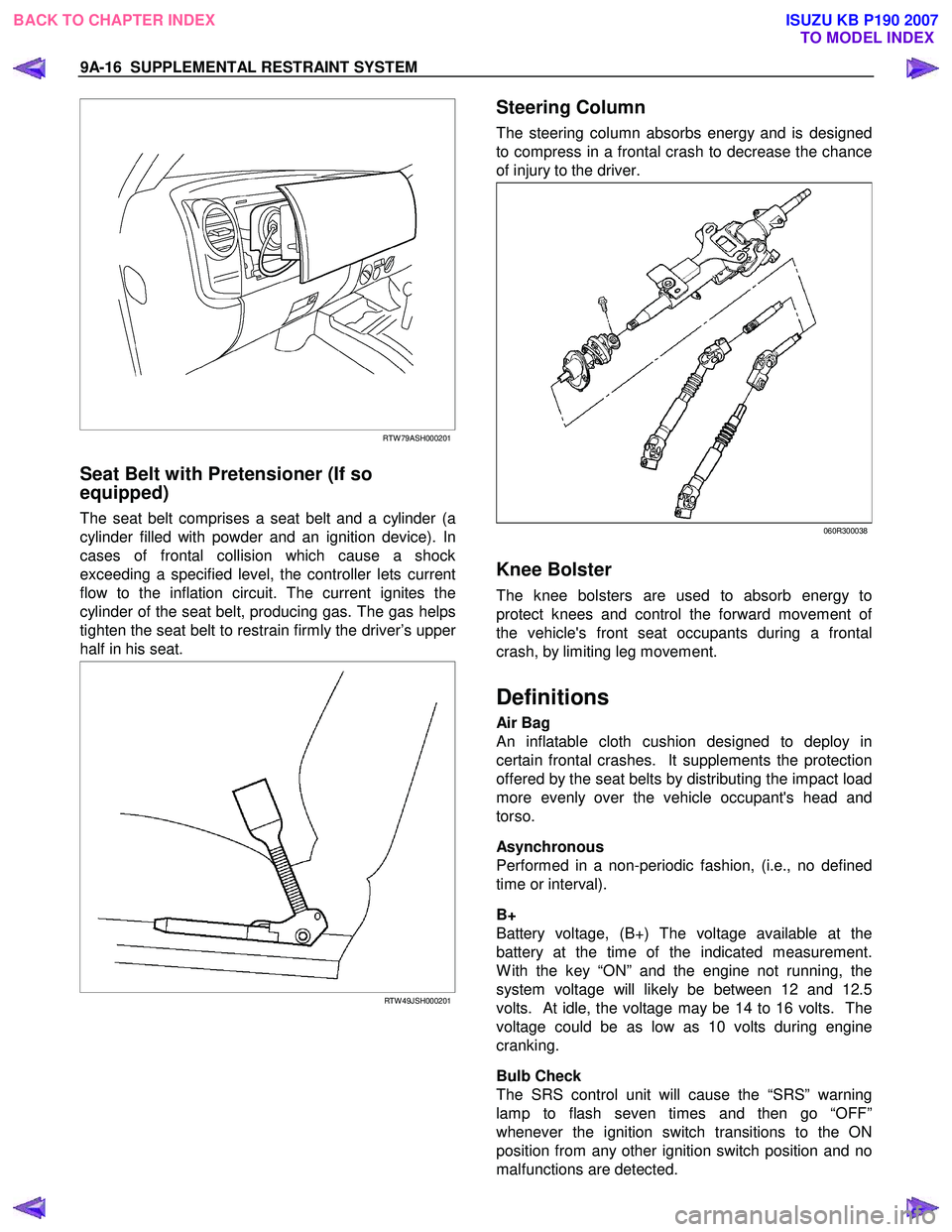
Seat Belt with Pretensioner (If so
equipped)
The seat belt comprises a seat belt and a cylinder (a
cylinder filled with powder and an ignition device). In
cases of frontal collision which cause a shock
exceeding a specified level, the controller lets current
flow to the inflation circuit. The current ignites the
cylinder of the seat belt, producing gas. The gas helps
tighten the seat belt to restrain firmly the driver’s uppe
r
half in his seat.
RTW 49JSH000201
Steering Column
The steering column absorbs energy and is designed
to compress in a frontal crash to decrease the chance
of injury to the driver.
060R300038
Knee Bolster
The knee bolsters are used to absorb energy to
protect knees and control the forward movement o
f
the vehicle's front seat occupants during a frontal
crash, by limiting leg movement.
Definitions
Air Bag
An inflatable cloth cushion designed to deploy in
certain frontal crashes. It supplements the protection
offered by the seat belts by distributing the impact load
more evenly over the vehicle occupant's head and
torso.
Asynchronous
Performed in a non-periodic fashion, (i.e., no defined
time or interval).
B+
Battery voltage, (B+) The voltage available at the
battery at the time of the indicated measurement.
W ith the key “ON” and the engine not running, the
system voltage will likely be between 12 and 12.5
volts. At idle, the voltage may be 14 to 16 volts. The
voltage could be as low as 10 volts during engine
cranking.
Bulb Check
The SRS control unit will cause the “SRS” warning
lamp to flash seven times and then go “OFF”
whenever the ignition switch transitions to the ON
position from any other ignition switch position and no
malfunctions are detected.
BACK TO CHAPTER INDEX TO MODEL INDEXISUZU KB P190 2007