Page 5169 of 6020

ELECTRICAL-BODY AND CHASSIS 8A-231
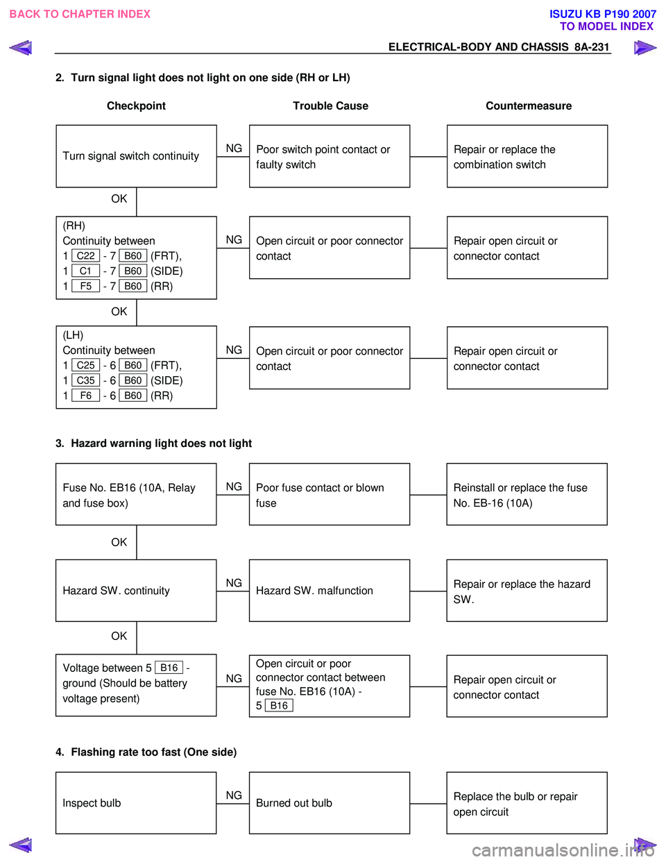
2. Turn signal light does not light on one side (RH or LH)
Checkpoint Trouble Cause Countermeasure
Repair open circuit or
connector contact
Open circuit or poor connector
contact
NG
(LH)
Continuity between
1
C25 - 6 B60 (FRT),
1
C35 - 6 B60 (SIDE)
1
F6 - 6 B60 (RR)
(RH)
Continuity between
1
C22 - 7 B60 (FRT),
1
C1 - 7 B60 (SIDE)
1
F5 - 7 B60 (RR)
Repair or replace the
combination switch
Turn signal switch continuity
Poor switch point contact or
faulty switch
NG
OK
OK
Repair open circuit or
connector contact
Open circuit or poor connector
contact
NG
3. Hazard warning light does not light
Repair or replace the hazard
SW .
Hazard SW . malfunction
NG
Voltage between 5
B16 -
ground (Should be battery
voltage present)
Hazard SW . continuity
Reinstall or replace the fuse
No. EB-16 (10A)
Fuse No. EB16 (10A, Relay
and fuse box)
Poor fuse contact or blown
fuse
NG
OK
OK
Repair open circuit or
connector contact
Open circuit or poor
connector contact between
fuse No. EB16 (10A) -
5
B16
NG
4. Flashing rate too fast (One side)
Replace the bulb or repair
open circuitInspect bulbBurned out bulb
NG
BACK TO CHAPTER INDEX TO MODEL INDEXISUZU KB P190 2007
Page 5170 of 6020
8A-232 ELECTRICAL-BODY AND CHASSIS
BACKUP LIGHT
1. Backup light does not light on one side (RH or LH)
Checkpoint Trouble Cause Countermeasure
Repair grounding point contactPoor ground contact
NGGrounding point
Replace the bulb or repair
connector contactBackup light bulb continuityBurned out bulb or poor
connector contact
NG
OK
2. Backup light does not light on both sides
Repair or replace the switch
Poor switch point contact of
faulty switch
NG
Voltage between 5 F6
(5
F5 ) - ground with
starter switch ON and shift
lev er into rev erse position
(Should be battery v oltage
present)
Back up light switch (mode
switch) continuity
Reinstall or replace fuse No.
C10 (15A)
Fuse No. C10 (15A, Fuse
box)
Poor fuse contact or blown
fuse
NG
OK
OK
Repair open circuit or
connector contact
Open circuit or poor connector
contact
NG
BACK TO CHAPTER INDEX
TO MODEL INDEXISUZU KB P190 2007
Page 5171 of 6020
ELECTRICAL-BODY AND CHASSIS 8A-233
HORN
1. Both sides of horn do not sound
Checkpoint Trouble Cause Countermeasure
Repair the grounding point
Poor ground contact
NG
Horn relay
Grounding point
Reinstall or replace fuse No.
EB15 (10A)
Fuse No EB15 (10A, Relay
and fuse box)
Poor fuse contact or blown
fuse
NG
OK
OK
Reinstall or replace the horn
relay
Poor relay contact or faulty
horn relay
NG
Voltage between connector
3
X3 - ground or 1 X3
- ground (Should be battery
v oltage present) OK
Repair open circuit or
reconnect the connector
Open circuit or poor connector
contact between fuse No.
EB15 (10A) and horn relay
NG
Remov e steering pad and
steering wheel
OK
Horn switch continuity
OK
Repair or replace the horn
switch
Poor switch point contact or
faulty switch
NG
Continuity between
5
X3 - 10 B60
2
X3 - 1 C20 (1 C21 )
OK
Repair open circuit or
connector contact
Open circuit or poor connector
contact
NG
BACK TO CHAPTER INDEX
TO MODEL INDEXISUZU KB P190 2007
Page 5172 of 6020
8A-234 ELECTRICAL-BODY AND CHASSIS
2. One side of horn does not blow
Checkpoint Trouble Cause Countermeasure
Repair open circuit or
reconnect the connector
Open circuit or poor connector
contact
NG Voltage between 1
C20
(1
C21 ) - ground with
horn switch depressed
(Should be battery voltage
present)
Replace the horn assembly
Horn continuity between
connectors
Faulty horn assembly
NG
OK
3. Insufficient horn volume
Clfean and/or remove the
foreign materialStain foreign material in the
horn
NGHorn
Recharge or replace the
batteryBattery conditionDischarged battery
NG
OK
BACK TO CHAPTER INDEX
TO MODEL INDEXISUZU KB P190 2007
Page 5177 of 6020

ELECTRICAL-BODY AND CHASSIS 8A-239
Bulb
Be absolutely sure that the rear combination light bulb is
correctly installed.
This will prevent a poor contact and an open circuit.
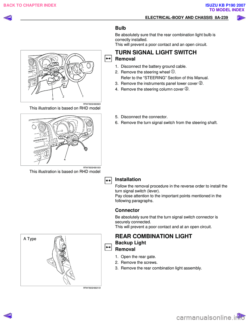
RTW 780SH000901
This illustration is based on RHD model
TURN SIGNAL LIGHT SWITCH
Removal
1. Disconnect the battery ground cable.
2. Remove the steering wheel
1.
Refer to the “STEERING” Section of this Manual.
3. Remove the instruments panel lower cover
2.
4. Remove the steering column cover
3.
RTW 780SH001001
This illustration is based on RHD model
5. Disconnect the connector.
6. Remove the turn signal switch from the steering shaft.
Installation
Follow the removal procedure in the reverse order to install the
turn signal switch (lever).
Pay close attention to the important points mentioned in the
following paragraphs.
Connector
Be absolutely sure that the turn signal switch connector is
securely connected.
This will prevent a poor contact and at an open circuit.
A Type
RTW 780SH002101
REAR COMBINATION LIGHT
Backup Light
Removal
1. Open the rear gate.
2. Remove the screws.
3. Remove the rear combination light assembly.
BACK TO CHAPTER INDEX TO MODEL INDEXISUZU KB P190 2007
Page 5178 of 6020
8A-240 ELECTRICAL-BODY AND CHASSIS
B Type
RTW 580SH000401
A Type
RTW 780SH001401
4. Turn the bulb 1 counterclockwise to remove it.
B Type
RTW 78ASH002601
Installation
Follow the removal procedure in the reverse order to install the
rear combination light.
Pay close attention to the important points mentioned in the
following paragraphs.
Bulbs
Be absolutely sure that each bulb is correctly installed.
This will prevent a poor contact and an open circuit.
RTW 780SH001501
This illustration is based on RHD model
HAZARD WARNING FLASHER SWITCH
Removal
1. Disconnect the battery ground cable.
2. Instrument Panel Cluster Assembly • Refer to Section 10 “BODY” for instrument panel cluste
r
assembly removal steps.
3. Hazard W arning Switch • Disconnect the switch connector.
• To remove the switch, push the lock from the back side
of the cluster assembly.
BACK TO CHAPTER INDEX TO MODEL INDEXISUZU KB P190 2007
Page 5179 of 6020

ELECTRICAL-BODY AND CHASSIS 8A-241
Installation
To install, follow the removal procedure in the reverse order.
Connector
Be absolutely sure that the hazard warning flasher switch
connector is securely connected.
This will prevent a poor contact and an open circuit.
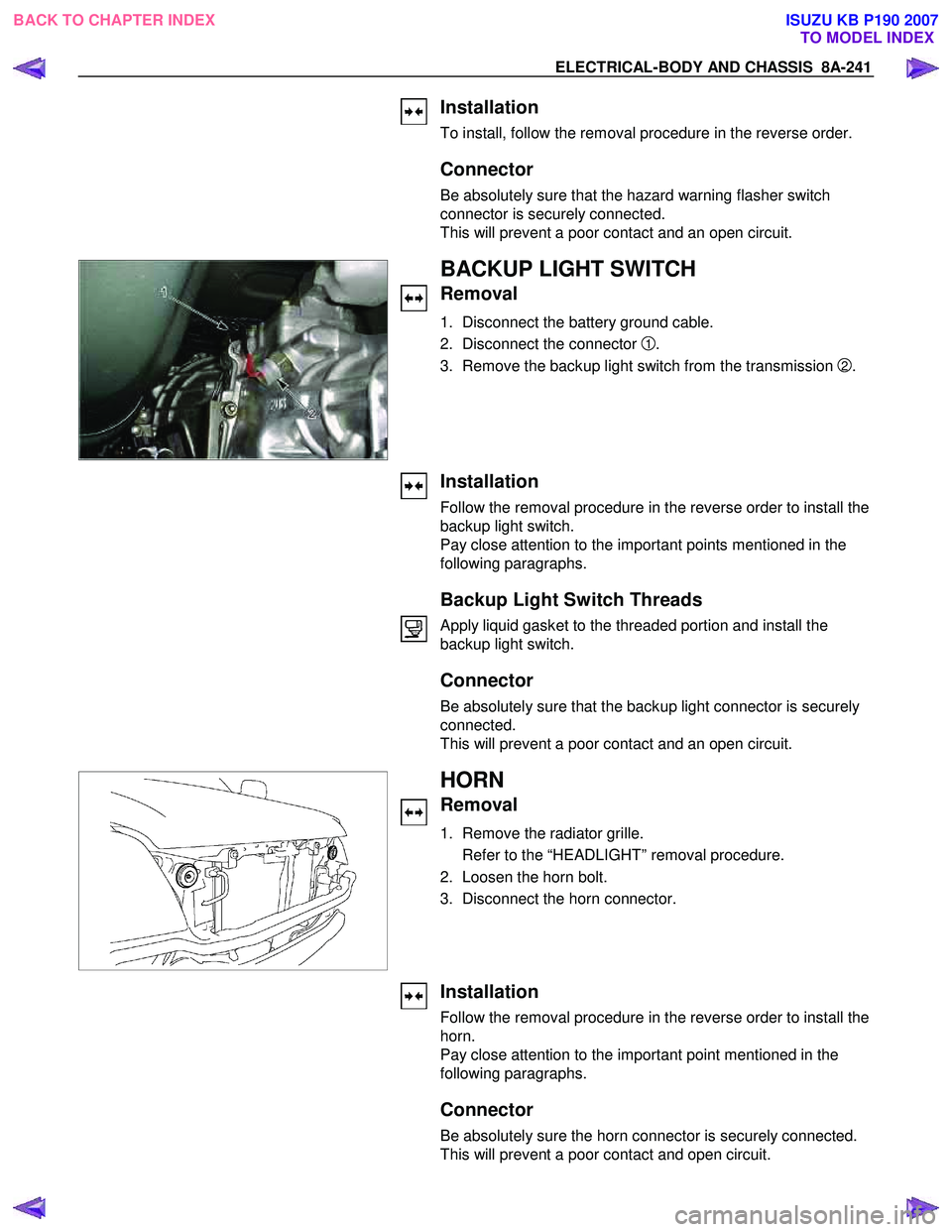
BACKUP LIGHT SWITCH
Removal
1. Disconnect the battery ground cable.
2. Disconnect the connector
1.
3. Remove the backup light switch from the transmission
2.
Installation
Follow the removal procedure in the reverse order to install the
backup light switch.
Pay close attention to the important points mentioned in the
following paragraphs.
Backup Light Switch Threads
Apply liquid gasket to the threaded portion and install the
backup light switch.
Connector
Be absolutely sure that the backup light connector is securely
connected.
This will prevent a poor contact and an open circuit.
HORN
Removal
1. Remove the radiator grille.
Refer to the “HEADLIGHT” removal procedure.
2. Loosen the horn bolt.
3. Disconnect the horn connector.
Installation
Follow the removal procedure in the reverse order to install the
horn.
Pay close attention to the important point mentioned in the
following paragraphs.
Connector
Be absolutely sure the horn connector is securely connected.
This will prevent a poor contact and open circuit.
BACK TO CHAPTER INDEX TO MODEL INDEXISUZU KB P190 2007
Page 5199 of 6020
ELECTRICAL-BODY AND CHASSIS 8A-261
DOOR SWITCH
Removal
1. Disconnect the battery ground cable.
2. Loosen the screw
1.
3. Remove the door switch
2.
4. Disconnect the door switch connector
3.
Installation
Follow the removal procedure in the reverse order to install the
spot light.
Pay close attention to the important points mentioned in the
following paragraphs.
Connector
Be absolutely sure that the door switch connector is securely
connected.
This will prevent a poor contact and an open circuit.
SPOTLIGHT (MAP Light)
Removal
1. Grasp the spotlight housing 1 with both hands.
Pull the housing straight down.
This will release the clip.
2. Disconnect the connector
2.
3. Turn socket
3 counterclockwise to remove it.
BACK TO CHAPTER INDEX TO MODEL INDEXISUZU KB P190 2007