Page 4847 of 6020
TRANSFER CASE 7D-17
LHD
RTW 77DMF000101
Legend
(1) Transfer Control Unit
(2) Nut
Removal
1. Disconnect the battery ground cable.
2. Disconnect the harness connector from the Transfe
r
control unit.
3. Remove the Transfer control unit.
Installation
1. Install the Transfer control unit.
Transfer control unit torque: 7 N ⋅
⋅⋅
⋅
m (0.7 kgf ⋅
⋅⋅
⋅
m/61 lb ⋅
⋅⋅
⋅
in)
2. Connect the harness connector to the Transfe
r
control unit.
3. Connect the battery ground cable.
BACK TO CHAPTER INDEX
TO MODEL INDEX
ISUZU KB P190 2007
Page 4917 of 6020
TRANSFER CONTROL SYSTEM 7D1-43
No. Connector face No. Connector face
E12
Natural green
Neutral switch E78
~
E80 NOT USED
E35
Black
Motor actuator E96
BlackReverse switch
E36
TACHO sensor E110
BrownBackup light switch
E42
Natural green
Backup light switch E111
BrownNeutral switch
E43
Natural green
Backup light switch E116
Backup light switch
E44
Black
Vehicle speed sensor F5
Gray Rear combination light-RH
E45
Gray
2W D-4W D switch F6
BlackRear combination light-LH
E46
Brown
H-L neutral switch H3
(HFV6
4JH1-TC)
Gray
GBattery (+) ~ Engine room
E51
Gray
Inhibiter switch (AW 30-40LE) H4
(HFV6)
(C24SE)
WhiteEngine room ~ Mission
E51
Black
Inhibitor switch (JR405E) H4
(4JH1-TC)
White
Engine ~ Engine room
BACK TO CHAPTER INDEX
TO MODEL INDEX
ISUZU KB P190 2007
Page 4918 of 6020
7D1-44 TRANSFER CONTROL SYSTEM
No. Connector face No. Connector face
H4
(4JJ1-TC)
White
Engine ~ Engine room H23
(4JA1-L)
WhiteEngine room B ~ T/misson
H5
(HFV6
4JH1-TC)
White
Engine room ~ Mission H27
NOT USED
H5
(4JJ1-TC
4JA1-L)
White
Engine ~ Engine room H29
(C24SE)
Battery (+) ~ Engine room
H6
White
Engine room ~ INST H32
(C24SE)
Engine room ~ Rear body
H7
White
Engine room ~ INST H48
WhiteEngine room ~ INST
H7
(4JJ1-TC)
White
Engine room ~ INST H50
Engine & Mission ~
H15
(HFV6
4JH1-TC)
Black
Engine room ~ Chassis M26
(C24SE)
Brown2W D-4W D switch
H15
(
4JJ1-TC,
4JA1-L)
Black
Engine room ~ Chassis M27
(C24SE)
BrownHead leveling neutral switch
H18
White
Engine room ~ INST P1
SilverBattery (+)
H23
White
Engine ~ Engine room B P2
SilverRelay & Fuse box
BACK TO CHAPTER INDEX
TO MODEL INDEX
ISUZU KB P190 2007
Page 4919 of 6020
TRANSFER CONTROL SYSTEM 7D1-45
No. Connector face No. Connector face
P5
Silver
Battery (-)
P6
Silver
Body earth (Ground)
P7
Battery (ALT)
P10
Silver
Engine ground
P11
Silver
Fuse & relay box
P13
Gray
Shift on the fly actuator
R14
Black
2W D-4W D control unit
R15
Black
2W D-4W D control unit
X12
Black
ECM main relay
BACK TO CHAPTER INDEX
TO MODEL INDEX
ISUZU KB P190 2007
Page 4939 of 6020

ELECTRICAL-BODY AND CHASSIS 8A-1
SECTION 8A
ELECTRICAL-BODY AND CHASSIS
TABLE OF CONTENTS
PAGE
General Information ........................................................................................................... .........8A- 4
Notes for Working on Electrical Items .......................................................................................8A - 5
Symbols and A bbreviations ..................................................................................................... ..8A- 11
Symbols ....................................................................................................................... ................ 8A- 11
Abbreviations ................................................................................................................. ..............8A- 12
Parts for Electri cal Circuit .................................................................................................. ........8A- 13
Wiring ........................................................................................................................ ...................8A- 13
Fuse .......................................................................................................................... ....................8A- 15
Fusible Link .................................................................................................................. ...............8A- 15
Relay ......................................................................................................................... ....................8A- 16
Diode ......................................................................................................................... ...................8A- 17
Connector ..................................................................................................................... ...............8A- 18
Battery ....................................................................................................................... ...................8A- 19
Reading the Circuit Diagram ................................................................................................... ...8A- 22
Parts Location ................................................................................................................ ..............8A- 22
Circuit Diagram ............................................................................................................... .............8A- 23
Connector List ................................................................................................................ .............8A- 23
Main Data and Specifications .................................................................................................. ...8A- 24
Bulb Specifications ........................................................................................................... ..........8A- 24
Relay and Fuse ................................................................................................................ ............8A- 26
Relay and Fuse Box Location (RHD) .........................................................................................8A- 26
Relay and Fuse Box Location (LHD) ..........................................................................................8A- 27
Relay Location ................................................................................................................ .............8A- 28
Fuse and Slow Blow Fuse Location ...........................................................................................8A- 31
Fuse Location ................................................................................................................. .............8A- 33
Diode Location ................................................................................................................ .............8A- 34
Fuse Block Circuit (C24SE) .................................................................................................... ....8A- 35/36
Fuse Block Circuit (HFV6) ...................................................................................................... .....8A- 37
BACK TO CHAPTER INDEX
TO MODEL INDEX
ISUZU KB P190 2007
Page 4942 of 6020

8A-4 ELECTRICAL-BODY AND CHASSIS
GENERAL INFORMATION
The body and chassis electrical system operates on a twelve volt power supply with negative ground polarity.
The main harness consists of the engine harness, the instrument harness, the body harness, and the chassis
harness.
The harnesses use a split corrugated tube to protect the wires from the elements.
W ire size is determined by current flow, circuit length, and voltage drop.
All wires have color-coded insulation.
W ire color-codes are shown in the circuit diagrams.
This makes it easier to trace circuits and to make the proper connections.
Each circuit consists of the following:
5. Power source – The battery and the alternator
5. W ires – To carry electrical current through the circuit
5. Fuses – To protect the circuit against current overload
5. Relays – To protect voltage drop between the battery and the circuit parts and to protect the switch points against burning
5. Switches – To open and close the circuit
5. Load – Any device, such as a light or motor, which converts the electrical current into useful work
5. Ground – To allow the current to flow back to the power source
BACK TO CHAPTER INDEX TO MODEL INDEXISUZU KB P190 2007
Page 4943 of 6020

ELECTRICAL-BODY AND CHASSIS 8A-5
NOTES FOR WORKING ON ELECTRICAL ITEMS
Battery
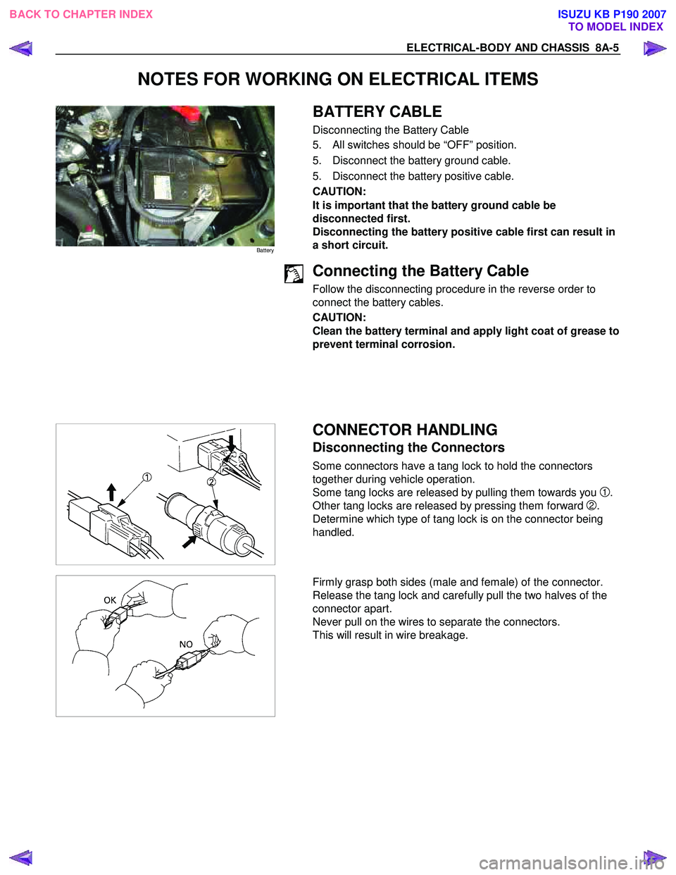
BATTERY CABLE
Disconnecting the Battery Cable
5. All switches should be “OFF” position.
5. Disconnect the battery ground cable.
5. Disconnect the battery positive cable.
CAUTION:
It is important that the battery ground cable be
disconnected first.
Disconnecting the battery positive cable first can result in
a short circuit.
Connecting the Battery Cable
Follow the disconnecting procedure in the reverse order to
connect the battery cables.
CAUTION:
Clean the battery terminal and apply light coat of grease to
prevent terminal corrosion.
CONNECTOR HANDLING
Disconnecting the Connectors
Some connectors have a tang lock to hold the connectors
together during vehicle operation.
Some tang locks are released by pulling them towards you
1.
Other tang locks are released by pressing them forward
2.
Determine which type of tang lock is on the connector being
handled.
Firmly grasp both sides (male and female) of the connector.
Release the tang lock and carefully pull the two halves of the
connector apart.
Never pull on the wires to separate the connectors.
This will result in wire breakage.
BACK TO CHAPTER INDEX TO MODEL INDEXISUZU KB P190 2007
Page 4954 of 6020

8A-16 ELECTRICAL-BODY AND CHASSIS
RELAY
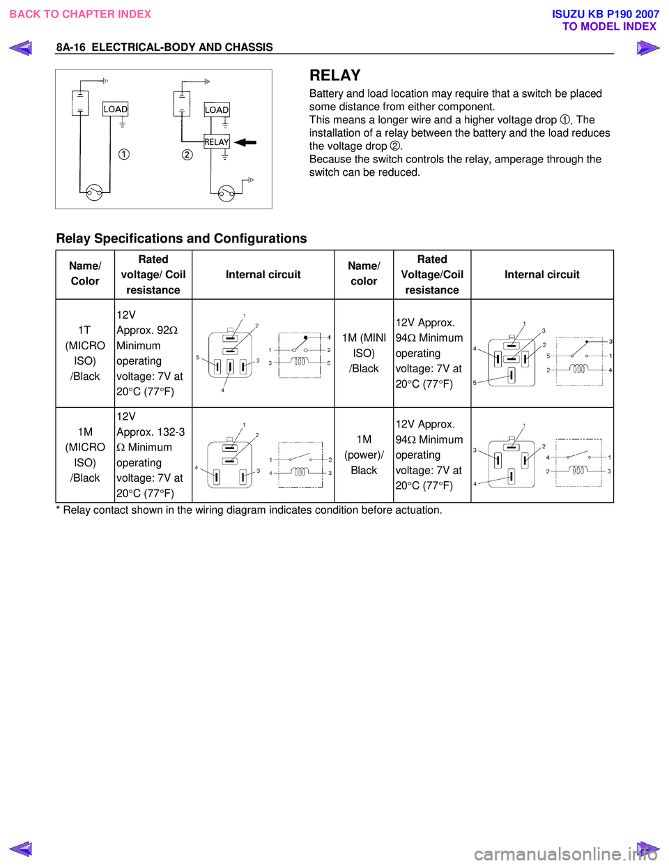
Battery and load location may require that a switch be placed
some distance from either component.
This means a longer wire and a higher voltage drop
1. The
installation of a relay between the battery and the load reduces
the voltage drop
2.
Because the switch controls the relay, amperage through the
switch can be reduced.
Relay Specifications and Configurations
Name/ Color Rated
voltage/ Coil resistance Internal circuit
Name/
color Rated
Voltage/Coil resistance Internal circuit
1T
(MICRO ISO)
/Black 12V
Approx. 92 Ω
Minimum
operating
voltage: 7V at
20 °C (77 °F)
1M (MINI
ISO)
/Black 12V Approx.
94 Ω Minimum
operating
voltage: 7V at
20 °C (77 °F)
1M
(MICRO ISO)
/Black 12V
Approx. 132-3
Ω Minimum
operating
voltage: 7V at
20 °C (77 °F)
1M
(power)/ Black 12V Approx.
94 Ω Minimum
operating
voltage: 7V at
20 °C (77 °F)
* Relay contact shown in the wiring diagram indicates condition before actuation.
BACK TO CHAPTER INDEX TO MODEL INDEXISUZU KB P190 2007