Page 4476 of 6020

7A3-22 ON-VEHICLE SERVICE (JR405E)
4. Install the transmission mount.
Bolt torque (rubber to transmission) :
50N·m (5.1 kgf·m/37 lb·ft)
Nut torque (rubber to crossmember) :
52N·m (5.3 kgf·m/38 lb·ft)
5. Install the 3rd crossmember.
Bolt and Nut torque : 67 N·m (6.8 kgf·m/49 lb·ft)
Bolt torque : 50 N·m (5.1 kgf·m/37 lb·ft)
6. Install the automatic transmission fluid cooling pipe.
7. Install the torque converter bolts.
Bolt torque : 29 N·m (3.0 kgf·m/22 lb·ft)
8. Install the undercover.
Bolt torque : 9 N·m (0.9 kgf·m/78 lb·in)
9. Install the ATF level dipstick and tube.
10. Install the fuel hose bracket.
Bolt torque : 10 N·m (1.0 kgf·m/87 lb·in)
11. Tighten the nuts securing the exhaust manifold and the exhaust pipe.
Bolt torque : 43 N·m (4.4 kgf·m/32 lb·ft)
12. Install the rear propeller shaft assembly.
Flange bolt torque : 59 N·m (6.0 kgf·m/43 lb·ft)
Center bearing bracket bolt torque :
69 N·m (7.0 kgf·m/51 lb·ft)
13. Install the shift cable.
14. Connect the negative battery cable.
15. Remove the safety stands.
16. Remove the wheels blocks.
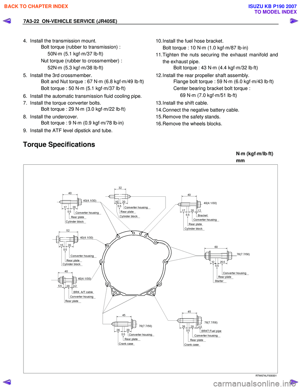
Torque Specifications
N ⋅
⋅⋅
⋅
m (kgf ⋅
⋅⋅
⋅
m/lb ⋅
⋅⋅
⋅
ft)
mm
RTW 67ALF000301
BACK TO CHAPTER INDEX
TO MODEL INDEX
ISUZU KB P190 2007
Page 4571 of 6020

MSG MODEL 7B-7
REMOVAL AND INSTALLATION
Read this Section carefully before performing any removal and installation procedure. This Section gives you
important points as well as the order of operation. Be sure that you understand everything in this Section before you
begin.
Important Operations - Removal
Battery Cable
Disconnect the negative (-) cable from the battery terminal.
Engine Hood
Apply setting marks to the engine hood and the engine hood
hinges before removing the engine hood.
Gear Shift Lever
1. Place the gear shift lever in the neutral position.
2. Remove the gear shift lever knob.
3. Remove the front console assembly.
4. Remove the gear shift lever grommet and dust cover.
5. Remove the gear shift lever cover bolts.
6. Remove the gear shift lever.
Note:
Cover the shift lever hole to prevent the entry of foreign
material into the transmission.
Lifting the Vehicle
1. Jack up the vehicle.
2. Place chassis stands at the front and the rear of the vehicle.
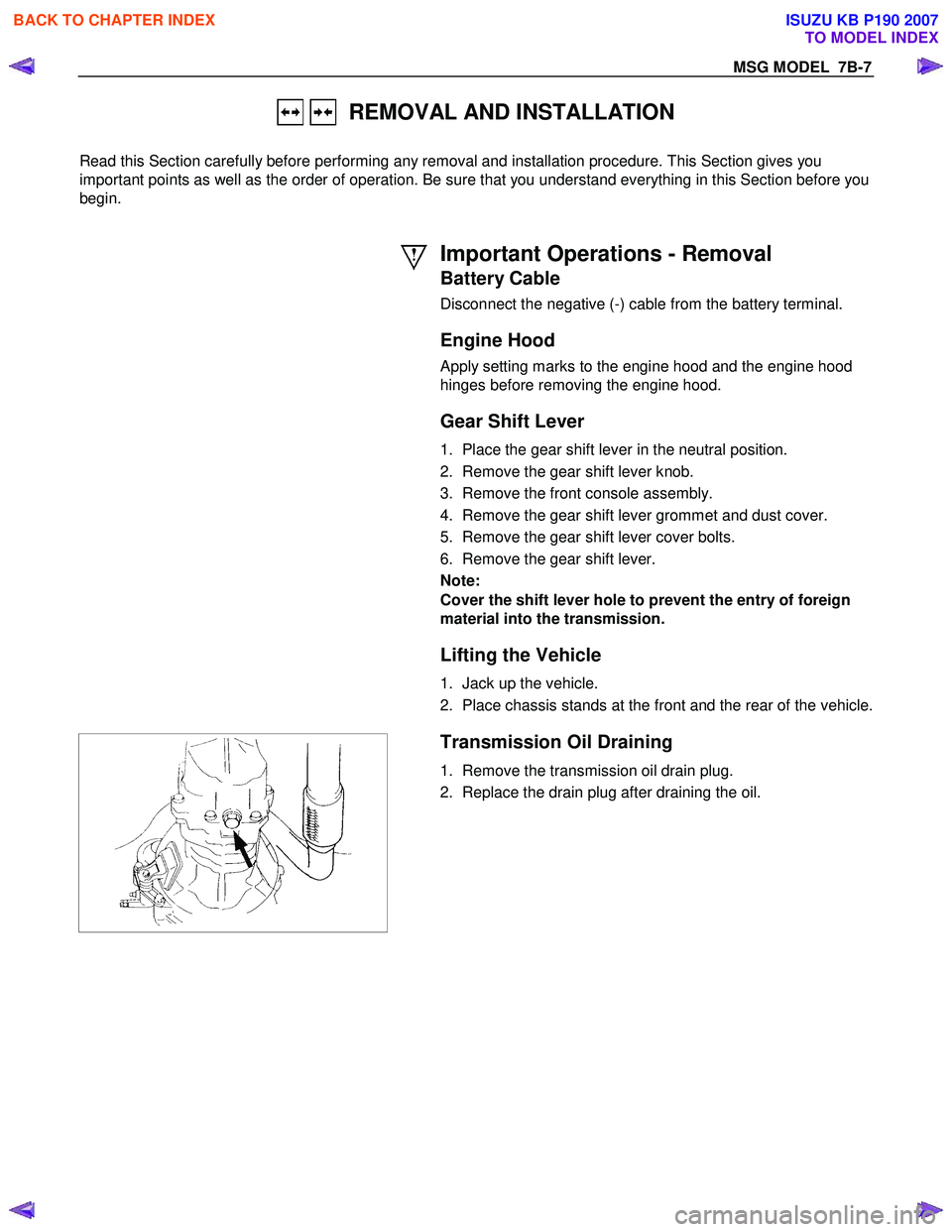
Transmission Oil Draining
1. Remove the transmission oil drain plug.
2. Replace the drain plug after draining the oil.
BACK TO CHAPTER INDEX
TO MODEL INDEX
ISUZU KB P190 2007
Page 4578 of 6020
7B-14 MSG MODEL
Gear Shift Lever
1. Replenish the transmission case with the specified engineoil.
Transmission Case Oil lit(US gal.)
1.55 (0.41)
2. Install the gear shift lever to the gear control box.
3. Tighten the gear shift lever cover bolts to the specified torque.
Shift Lever Cover Bolt Torque N⋅m(kgf ⋅m/lb ⋅ft)
20 (2.0 / 14)
4. Install the dust cover and the grommet.
5. Install the front console assembly.
6. Install the gear shift lever knob.
Lowering the Vehicle
1. Place a jack beneath the vehicle.
2. Raise the jack to remove the chassis stands.
3. Lower the vehicle to the ground.
Engine Hood
Align the setting marks(applied at removal)on the engine hood
and the engine hood hinges to install the engine hood.
Battery Cable
Connect the negative (-) cable to the battery terminal.
BACK TO CHAPTER INDEX
TO MODEL INDEX
ISUZU KB P190 2007
Page 4614 of 6020
7B1-8 MANUAL TRANSMISSION
Removal
1. Disconnect the battery ground cable.
2. Remove the gear control lever knob.
3. Remove the rear floor console. (Bucket seat)
Refer to the section “Floor Console”.
4. Remove the front floor console.
Refer to the section “Floor Console”.
745R300006
Legend
(1) Knob
(2) Rear Floor Console
(3) Front Floor Console
5. Remove the grommet assembly.
RTW 47BMH000101
Legend
(1) Grommet Assembly
(2) Floor Panel
(3) Front
BACK TO CHAPTER INDEX
TO MODEL INDEX
ISUZU KB P190 2007
Page 4621 of 6020

MANUAL TRANSMISSION 7B1-15
13. Install the rear propeller shaft.
Torque: 59 N ⋅
⋅⋅
⋅
m (6.0 kgf ⋅
⋅⋅
⋅
m/43 lb ⋅
⋅⋅
⋅
ft)
14. Install the center bearing on crossemember.
Torque: 69 N ⋅
⋅⋅
⋅
m (7.0 kgf ⋅
⋅⋅
⋅
m/51 lb ⋅
⋅⋅
⋅
ft)
15. Install the gear control lever.
Torque: 19 N ⋅
⋅⋅
⋅
m (1.9 kgf ⋅
⋅⋅
⋅
m/14 lb ⋅
⋅⋅
⋅
ft)
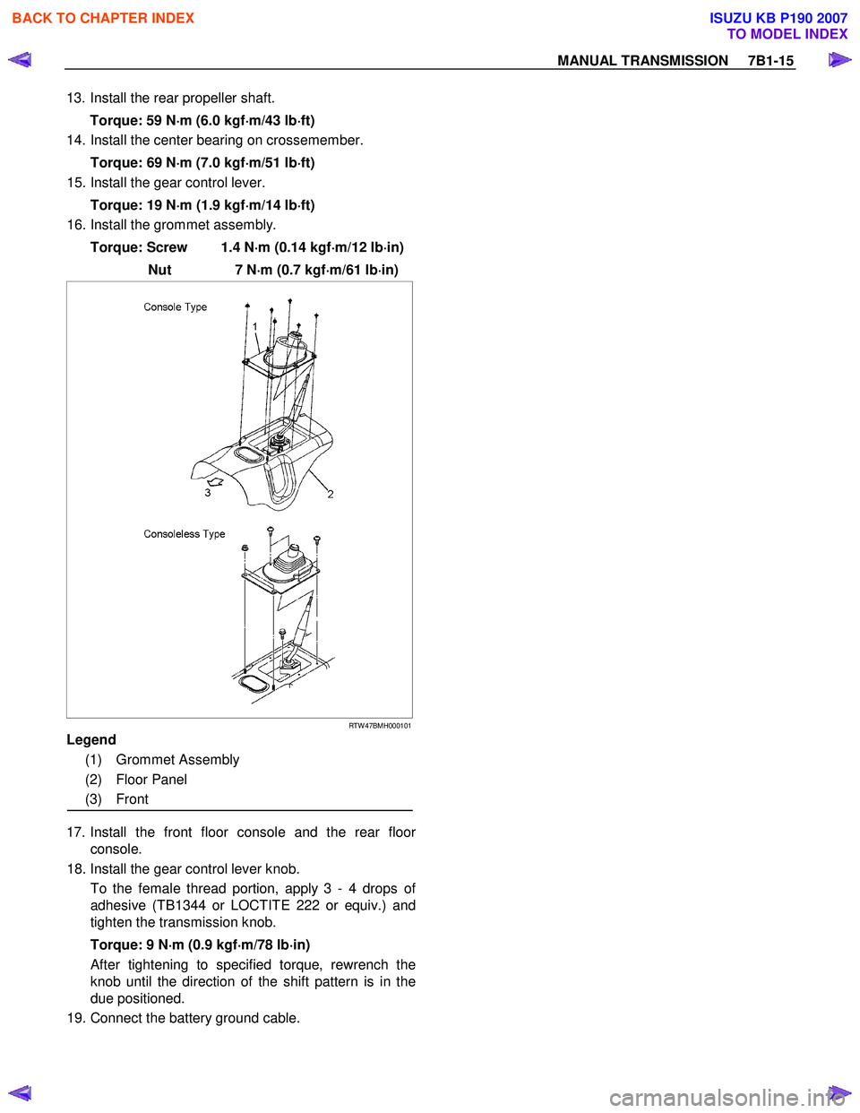
16. Install the grommet assembly.
Torque: Screw 1.4 N ⋅
⋅⋅
⋅
m (0.14 kgf ⋅
⋅⋅
⋅
m/12 lb ⋅
⋅⋅
⋅
in)
Nut 7 N ⋅
⋅⋅
⋅
m (0.7 kgf ⋅
⋅⋅
⋅
m/61 lb ⋅
⋅⋅
⋅
in)
RTW 47BMH000101
Legend
(1) Grommet Assembly
(2) Floor Panel
(3) Front
17. Install the front floor console and the rear floor
console.
18. Install the gear control lever knob.
To the female thread portion, apply 3 - 4 drops o
f
adhesive (TB1344 or LOCTITE 222 or equiv.) and
tighten the transmission knob.
Torque: 9 N ⋅
⋅⋅
⋅
m (0.9 kgf ⋅
⋅⋅
⋅
m/78 lb ⋅
⋅⋅
⋅
in)
After tightening to specified torque, rewrench the knob until the direction of the shift pattern is in the
due positioned.
19. Connect the battery ground cable.
BACK TO CHAPTER INDEX
TO MODEL INDEX
ISUZU KB P190 2007
Page 4668 of 6020
7B1-62 MANUAL TRANSMISSION
Removal
1. Disconnect the battery ground cable.
2. Remove the gear control lever knob.
3. Remove the rear floor console. (Bucket seat)
Refer to the section “Floor Console”.
4. Remove the front floor console.
Refer to the section “Floor Console”.
745R300006
Legend
(1) Knob
(2) Rear Floor Console
(3) Front Floor Console
5. Remove the grommet assembly.
RTW 47BMH000101
Legend
(1) Grommet Assembly
(2) Floor Panel
(3) Front
BACK TO CHAPTER INDEX
TO MODEL INDEX
ISUZU KB P190 2007
Page 4676 of 6020

7B1-70 MANUAL TRANSMISSION
15. Tighten the exhaust pipe fixing nuts to the specified
torque. (Diesel engine only)
Torque: 67 N ⋅
⋅⋅
⋅
m (6.8 kgf ⋅
⋅⋅
⋅
m/49 lb ⋅
⋅⋅
⋅
ft)
RTW 67BSH000101
16. Install the front propeller shaft.
Refer to the section “Front Propeller Shaft”.
17. Install the rear propeller shaft.
Torque: 59 N ⋅
⋅⋅
⋅
m (6.0 kgf ⋅
⋅⋅
⋅
m/43 lb ⋅
⋅⋅
⋅
ft)
18. Install the center bearing on crossmember.
Torque: 69 N ⋅
⋅⋅
⋅
m (7.0 kgf ⋅
⋅⋅
⋅
m/51 lb ⋅
⋅⋅
⋅
ft)
19. Install the gear control lever.
Torque: 19 N ⋅
⋅⋅
⋅
m (1.9 kgf ⋅
⋅⋅
⋅
m/14 lb ⋅
⋅⋅
⋅
ft)
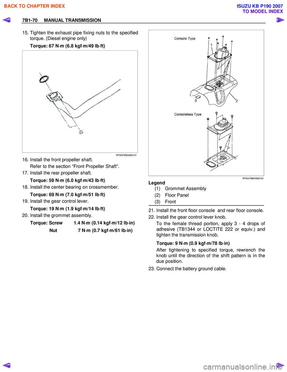
20. Install the grommet assembly.
Torque: Screw 1.4 N ⋅
⋅⋅
⋅
m (0.14 kgf ⋅
⋅⋅
⋅
m/12 lb ⋅
⋅⋅
⋅
in)
Nut 7 N ⋅
⋅⋅
⋅
m (0.7 kgf ⋅
⋅⋅
⋅
m/61 lb ⋅
⋅⋅
⋅
in)
RTW 47BMH000101
Legend
(1) Grommet Assembly
(2) Floor Panel
(3) Front
21. Install the front floor console and rear floor console.
22. Install the gear control lever knob. To the female thread portion, apply 3 - 4 drops o
f
adhesive (TB1344 or LOCTITE 222 or equiv.) and
tighten the transmission knob.
Torque: 9 N ⋅
⋅⋅
⋅
m (0.9 kgf ⋅
⋅⋅
⋅
m/78 lb ⋅
⋅⋅
⋅
in)
After tightening to specified torque, rewrench the
knob until the direction of the shift pattern is in the
due position.
23. Connect the battery ground cable.
BACK TO CHAPTER INDEX
TO MODEL INDEX
ISUZU KB P190 2007
Page 4727 of 6020
7B1-8 Manual Transmission (MUX)
Transmission Assembly
Removal
1. Disconnect battery ground cable.
2. Remove the gear control knob.
3. Remove the rear floor console. (Bucket seat) Refer to the section "Floor Console".
4. Remove the front floor console. Refer to the section "Floor Console".
Legend 1. Gear control knob
2. Rear floor console
3. Front floor console
5. Remove the grommet assembly.
Legend 1. Grommet assembly
2. Floor panel
3. Front
6. Remove the gear control lever (1).
7. Raise and support vehicle with suitable stands.
8. Remove the rear propeller shaft.
RTW77BSH000101
1
32
RTW77BMH000101
1
2
3
RTW77BSH007101
1
BACK TO CHAPTER INDEX
TO MODEL INDEX
ISUZU KB P190 2007