2007 ISUZU KB P190 service
[x] Cancel search: servicePage 3588 of 6020
Charging System – V6 Page 6D1-1-1
6D1-1
Charging System – V6
ATTENTION
Before performing any service operations or other procedure described in this Section, refer to
1.2 WARNING, CAUTION and NOTES for correct workshop practices with regard to safety and / or
property damage.
1 General Information ............................................................................................................ ...................3
1.1 Components ........................................................................................................................................................... 3
Generator................................................................................................................................................................ 3
Generator Types ................................................................................................................................................ 3
Voltage Regulator .................................................................................................................................................. 4
1.2 WARNING, CAUTION and NOTES..................................................................................................... .................... 4
Definition of WARNING, CAUTION and NOTE Statements............................................................................. .... 4
W ARNING defined ............................................................................................................................................. 4
CAUTION defined .............................................................................................................................................. 5
NOTE defined .................................................................................................................................................... 5
1.3 System Operation .................................................................................................................................................. 5
Operation ........................................................................................................................................................... 5
Alternator W arning ............................................................................................................. ................................ 6
2 Diagnosis ................................................................................................................................................7
2.1 Diagnostic General Information ........................................................................................................................... 7
Basic Diagnostic Tools Required ................................................................................................ ......................... 7
2.2 Tech 2 Data List ..................................................................................................................................................... 7
2.3 Diagnostic Systems Check ....................................................................................................... ............................ 7
2.4 Wiring Diagram ...................................................................................................................................................... 8
2.5 Charging System Inoperative / Malfunctioning ................................................................................................... 9
Diagnostic Table Notes ......................................................................................................... ............................. 9
Diagnostic Table 120A Generator ................................................................................................ ...................... 9
3 Minor Service Operations ....................................................................................................................10
3.1 Safety Precautions............................................................................................................................................... 10
3.2 Maintenance ......................................................................................................................................................... 10
Regular Checks................................................................................................................. ................................... 10
Lubrication ....................................................................................................................................................... 10
3.3 On-vehicle Testing ............................................................................................................. .................................. 11
Generator On-vehicle Checks.................................................................................................... ......................... 11
Prerequisites .................................................................................................................................................... 11
Generator Test ................................................................................................................................................. 11
Charging Circuit Voltage Drop Test ............................................................................................. ...................... 13
Prerequisites .................................................................................................................................................... 13
Voltage Drop Test ............................................................................................................................................ 13
4 Major Service Operations ....................................................................................................................15
4.1 Generator.............................................................................................................................................................. 15
Remove ................................................................................................................................................................. 15
Reinstall ................................................................................................................................................................ 16
4.2 Generator Mounting Bracket ..................................................................................................... ......................... 17
Remove ................................................................................................................................................................. 17
Reinstall ................................................................................................................................................................ 17
BACK TO CHAPTER INDEX
TO MODEL INDEX
ISUZU KB P190 2007
Page 3590 of 6020
Charging System – V6 Page 6D1-1-3
1 General Information
1.1 Components
Generator
The Mitsubishi generator can be identified visually by its two lower and one upper mounting lugs.
It is mounted to the lower right-hand side of the engine block. It is driven by the same drive belt that drives other engine
ancillaries and requires no periodic drive belt adjustment.
The generator has three phases, incorporating a rotor with six pole pairs fitted and two internal cooling fans; one on the
drive-end and one on the slip-ring end. The rotor is supported by ball bearings in both the drive and slip-ring end
housings. Surrounding the rotor is a stator, which has a three phase delta connected output winding construction on a
ring shaped lamination pack.
The output of the stator winding is rectified by eight diodes that are contained within the slip-ring end housing. Excitation
current is supplied to the rotor field coil via the voltage regulator, the brushes and slip-rings. The electronic voltage
regulator requires no adjustment in service.
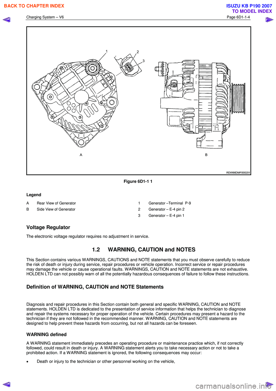
The generator has four external connections (refer to Figure 6D1-1 1):
• Generator – Terminal P-9 to the battery positive terminal P-1 via fuse SBF1,
• Generator – E-4 pin 1 to the ECM connection E-60 pin 43 – regulator monitoring,
• Generator – E-4 pin 2 to the ECM connection E60 pin 21 – battery voltage sensing, and
• ground connection via the installation bolts.
Generator Types
The vehicle is fitted with a 120 amp generator.
BACK TO CHAPTER INDEX
TO MODEL INDEX
ISUZU KB P190 2007
Page 3591 of 6020
Charging System – V6 Page 6D1-1-4
Figure 6D1-1 1
Legend
A Rear View of Generator
B Side View of Generator
1 Generator –Terminal P-9
2 Generator – E-4 pin 2
3 Generator – E-4 pin 1
Voltage Regulator
The electronic voltage regulator requires no adjustment in service.
1.2 WARNING, CAUTION and NOTES
This Section contains various W ARNINGS, CAUTIONS and NOTE statements that you must observe carefully to reduce
the risk of death or injury during service, repair procedures or vehicle operation. Incorrect service or repair procedures
may damage the vehicle or cause operational faults. W ARNINGS, CAUTION and NOTE statements are not exhaustive.
HOLDEN LTD can not possibly warn of all the potentially hazardous consequences of failure to follow these instructions.
Definition of WARNING, CAUTION and NOTE Statements
Diagnosis and repair procedures in this Section contain both general and specific W ARNING, CAUTION and NOTE
statements. HOLDEN LTD is dedicated to the presentation of service information that helps the technician to diagnose
and repair the systems necessary for proper operation of the vehicle. Certain procedures may present a hazard to the
technician if they are not followed in the recommended manner. W ARNING, CAUTION and NOTE statements are
designed to help prevent these hazards from occurring, but not all hazards can be foreseen.
WARNING defined
A W ARNING statement immediately precedes an operating procedure or maintenance practice which, if not correctly
followed, could result in death or injury. A W ARNING statement alerts you to take necessary action or not to take a
prohibited action. If a W ARNING statement is ignored, the following consequences may occur:
• Death or injury to the technician or other personnel working on the vehicle,
BACK TO CHAPTER INDEX
TO MODEL INDEX
ISUZU KB P190 2007
Page 3596 of 6020
Charging System – V6 Page 6D1-1-9
2.5 Charging System Inoperative /
Malfunctioning
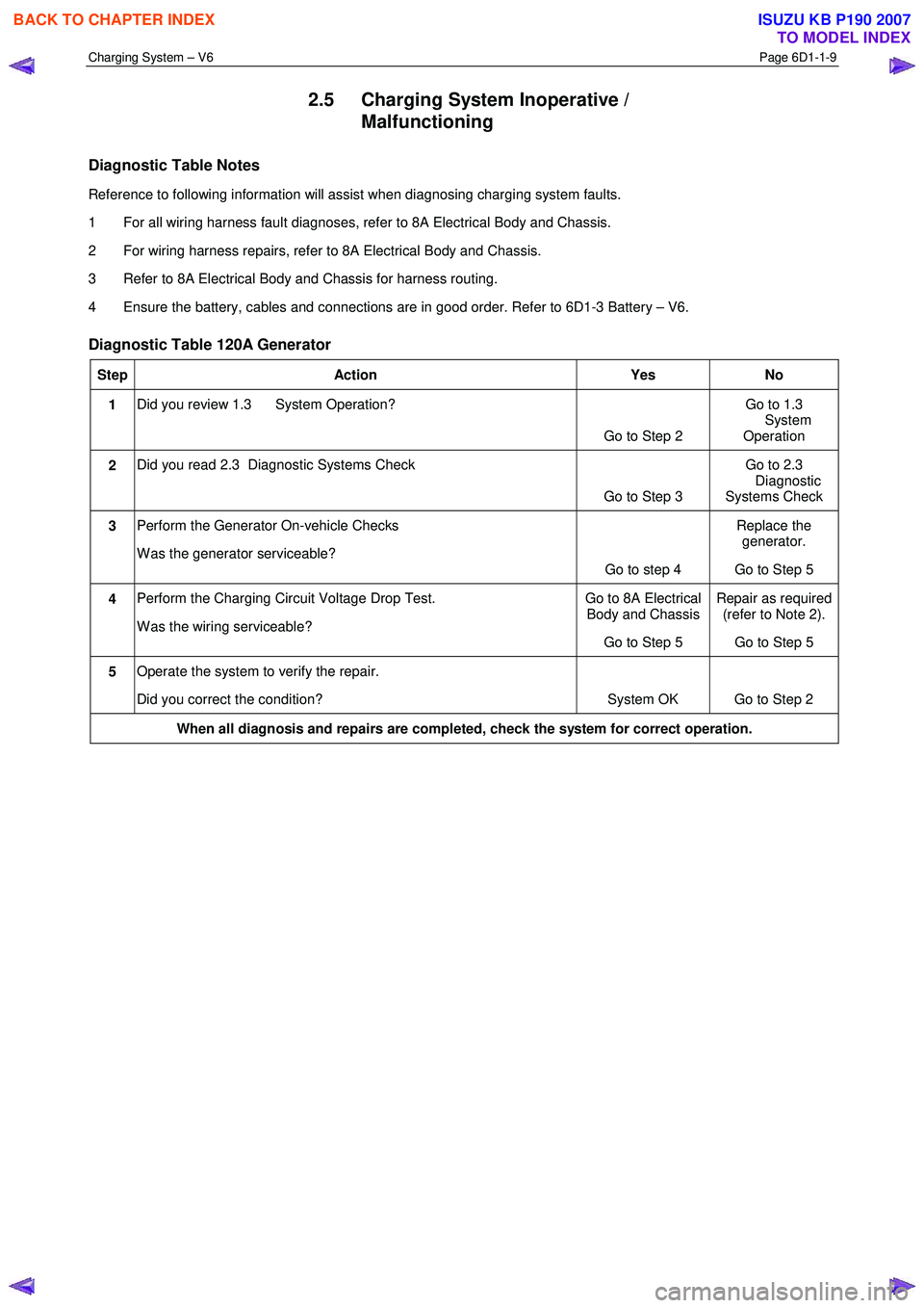
Diagnostic Table Notes
Reference to following information will assist when diagnosing charging system faults.
1 For all wiring harness fault diagnoses, refer to 8A Electrical Body and Chassis.
2 For wiring harness repairs, refer to 8A Electrical Body and Chassis.
3 Refer to 8A Electrical Body and Chassis for harness routing.
4 Ensure the battery, cables and connections are in good order. Refer to 6D1-3 Battery – V6.
Diagnostic Table 120A Generator
Step Action Yes No
1 Did you review 1.3 System Operation?
Go to Step 2 Go to 1.3
System Operation
2 Did you read 2.3 Diagnostic Systems Check
Go to Step 3 Go to 2.3
Diagnostic
Systems Check
3 Perform the Generator On-vehicle Checks
W as the generator serviceable? Go to step 4 Replace the
generator.
Go to Step 5
4 Perform the Charging Circuit Voltage Drop Test.
W as the wiring serviceable? Go to 8A Electrical
Body and Chassis
Go to Step 5 Repair as required
(refer to Note 2).
Go to Step 5
5 Operate the system to verify the repair.
Did you correct the condition? System OK Go to Step 2
When all diagnosis and repairs are completed, check the system for correct operation.
BACK TO CHAPTER INDEX
TO MODEL INDEX
ISUZU KB P190 2007
Page 3597 of 6020
Charging System – V6 Page 6D1-1-10
3 Minor Service Operations
3.1 Safety Precautions
Observe the following precautions. Failure to observe these precautions will result in serious damage to the generator.
• Only use the generator and voltage regulator in a negative ground system.
• Always refer to 1.2 W ARNING, CAUTION and NOTES before disconnecting the battery.
• W hen installing a battery, fit the positive (+) cable to the battery before fitting the negative cable.
• W hen a slave battery is used for starting purposes, ensure that both batteries are connected in parallel. That is,
positive terminals connected and negative terminals connected.
• Only use jumper leads that have surge protection.
• Disconnect both battery cables when charging the battery. This isolates the generator from the battery and from
the external charging equipment.
• Do not operate the generator within an open circuit or without a battery in the circuit.
• Do not disconnect the battery while the generator is running.
• Do not attempt to polarise the generator.
• Do not connect generator connector E-4 pin 1 to 12 V (the battery or ignition circuits).
• Some battery powered timing lights can produce high transient voltages when connected or disconnected.
Only disconnect or connect timing lights when the engine is switched off.
Ensure the generator connector E-4 pin 1 has
a maximum sinking current of 50mA.
3.2 Maintenance
Regular Checks
Check the following at regular intervals:
• generator terminals – for corrosion and loose connections,
• wiring – for continuity and damaged insulation,
• mounting bolts – for tightness,
• drive belt – for alignment and wear, and
• drive pulley – for damage and warping.
NOTE
The drive-belt adjustment for the engine
ancillaries (i.e. generator and water pump) is
provided by a spring-loaded tensioner. Therefore,
the drive belt does not require manual
adjustment.
Lubrication
High tolerance bearings are used in this generator. If the bearings are removed during the generator disassembly, new
bearings must be installed to restore the generator to original specification. The ball bearings supporting the rotor shaft
are pre-lubricated and sealed. Do not attempt to lubricate these during servicing.
BACK TO CHAPTER INDEX
TO MODEL INDEX
ISUZU KB P190 2007
Page 3602 of 6020

Charging System – V6 Page 6D1-1-15
4 Major Service Operations
4.1 Generator
Remove
Refer to 1.2 WARNING, CAUTION and NOTES
before disconnecting the battery.
1 Disconnect the battery ground lead P-5. Refer to 8A Electrical Body and Chassis.
2 Insert a ½ inch drive socket bar into the tensioner arm and rotate the tensioner arm clockwise.
3 Remove the drive belt from the generator pulley and release the tensioner. Refer to 6A1 Engine Mechanical – V6 for further details as required.
4 Pull the battery harness cap back from generator terminal P-9 (3), remove the nut (4) and remove the
positive lead (2) from the generator (5).
5 Disengage the connector retaining clip and remove the connector E-4, (1) from the generator.
Figure 6D1-1 4
6 Remove the three bolts (1, 2, 4) retaining the generator (3) to the generator bracket.
7 Remove the generator assembly from the vehicle.
Figure 6D1-1 5
BACK TO CHAPTER INDEX
TO MODEL INDEX
ISUZU KB P190 2007
Page 3605 of 6020
Charging System – V6 Page 6D1-1-18
4.3 Drive Belt Routing
Without Air Conditioning
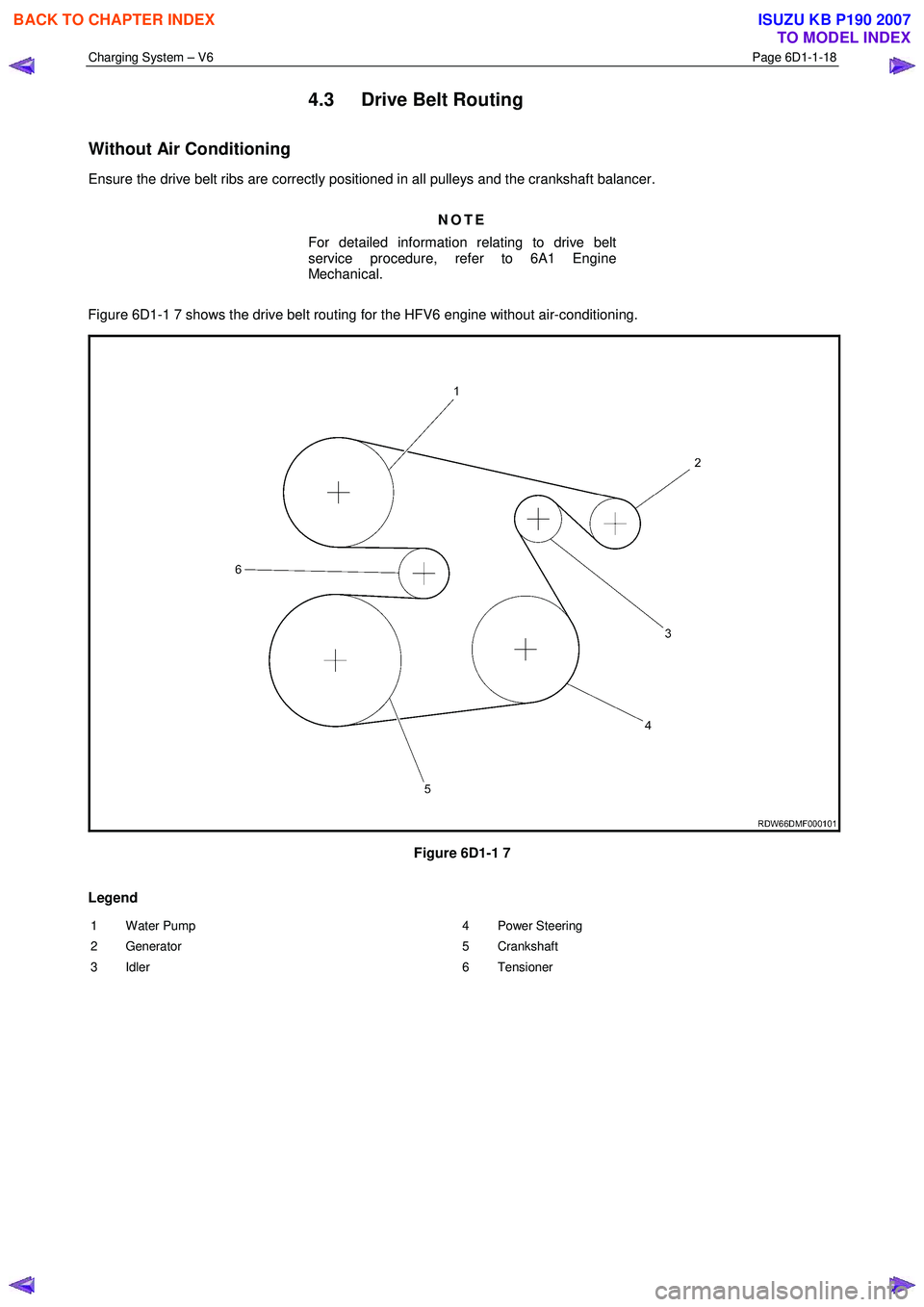
Ensure the drive belt ribs are correctly positioned in all pulleys and the crankshaft balancer.
NOTE
For detailed information relating to drive belt
service procedure, refer to 6A1 Engine
Mechanical.
Figure 6D1-1 7 shows the drive belt routing for the HFV6 engine without air-conditioning.
Figure 6D1-1 7
Legend
1 Water Pump
2 Generator
3 Idler 4 Power Steering
5 Crankshaft
6 Tensioner
BACK TO CHAPTER INDEX
TO MODEL INDEX
ISUZU KB P190 2007
Page 3606 of 6020
Charging System – V6 Page 6D1-1-19
6 Specifications
Ground Polarity...........................................................................................................Negative
Nominal Voltage ............................................................................................................... 1 2 V
Nominal Output............................................................................................................... 12 0 A
Stator Phases .................................................................................................................. ....... 3
Stator W inding Connections ............................................................................................ Delta
Voltage Regulator Setting................................................................................... 14.2 – 14.8 V
Rotor W inding Resistance @ 20 °C ................................................................................. 2.1 V
Slip-ring Outer Diameter ............................................................................................. 22.7 mm
Slip-ring Service Limit ................................................................................................. 22.1 mm
Stator W inding Resistance @ 20 °C ............................................................................ 0.098 Ω
Brush Length New ...................................................................................................... 18.5 mm
Minimum Brush Length................................................................................................. 5.0 mm
Direction of Rotation (viewed from pulley) ................................................................Clockwise
BACK TO CHAPTER INDEX
TO MODEL INDEX
ISUZU KB P190 2007