2007 ISUZU KB P190 service
[x] Cancel search: servicePage 3627 of 6020
Starting System – V6 Page 6D1-2–19
4 Major Service Operations
Disconnection of the battery affects certain
vehicle electronic systems. Refer to 00
Warnings, Cautions and Notes before
disconnecting the battery.
4.1 Starter Motor
Remove
The starter motor is in close proximity to the
left-hand side exhaust manifold and engine
pipe. Allow the engine to cool before
attempting to remove the starter motor.
1 Refer to 1.1 W ARNING, CAUTION and NOTES in this Service Information before disconnecting the battery.
2 Disconnect the battery ground lead.
3 Raise the front of the vehicle. For jacking locations, refer to 0A General Information.
4 Put safety stands in place.
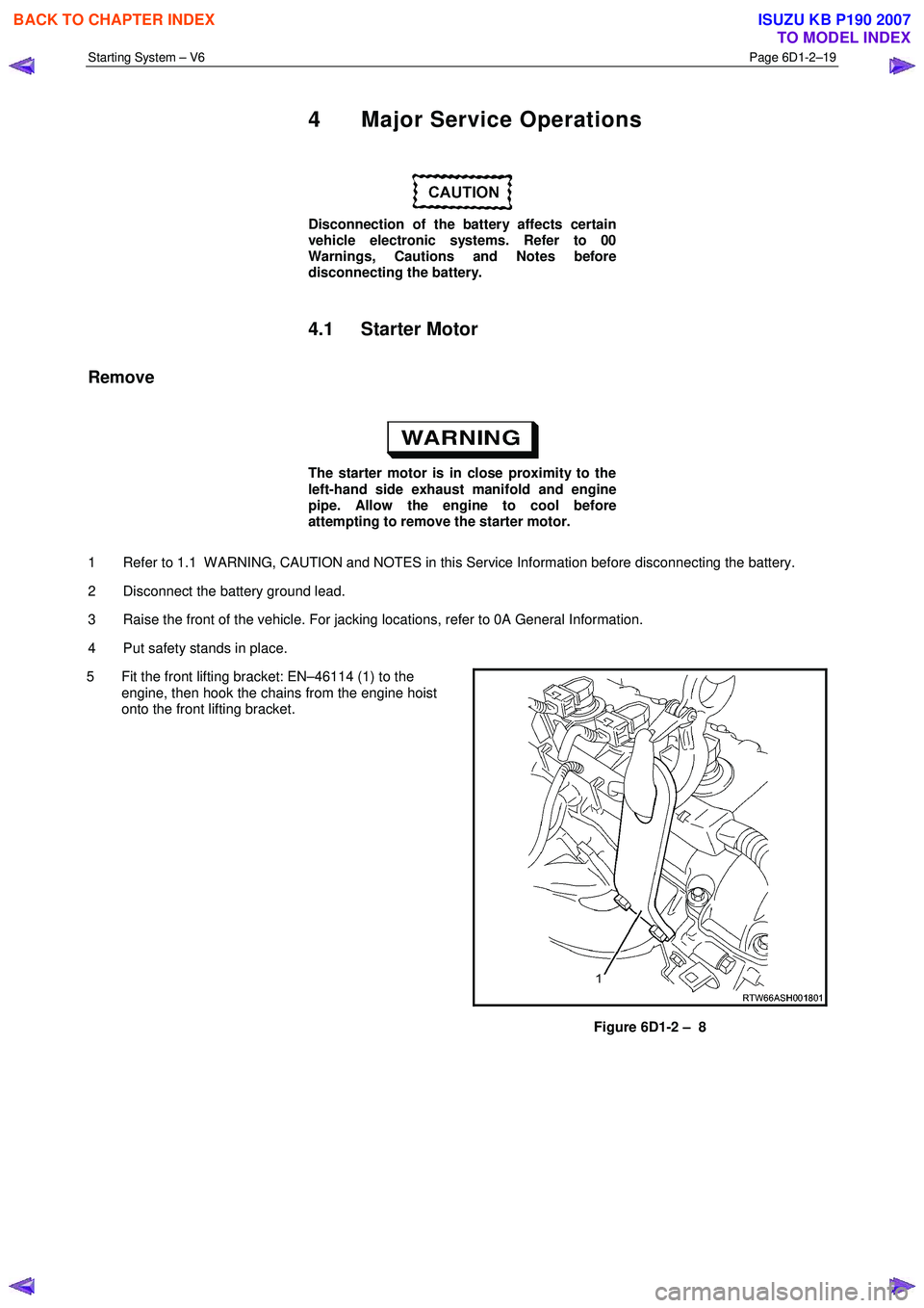
5 Fit the front lifting bracket: EN–46114 (1) to the engine, then hook the chains from the engine hoist
onto the front lifting bracket.
Figure 6D1-2 – 8
BACK TO CHAPTER INDEX
TO MODEL INDEX
ISUZU KB P190 2007
Page 3630 of 6020
Starting System – V6 Page 6D1-2–22
4.3 Starter Motor Bench Tests
Preliminary Checks
1 Check the drive assembly is fully retracted.
2 Check the drive assembly pinion turns freely on the planetary drive shaft.
3 Perform the No Load Test (as outlined in this Section) if the drive assembly is not fully retracted.
4 Disassemble and service the starter motor if it fails the No Load test, refer to 4.4 Starter Motor Disassemble and
Reassemble in this Section.
Pull-in Test
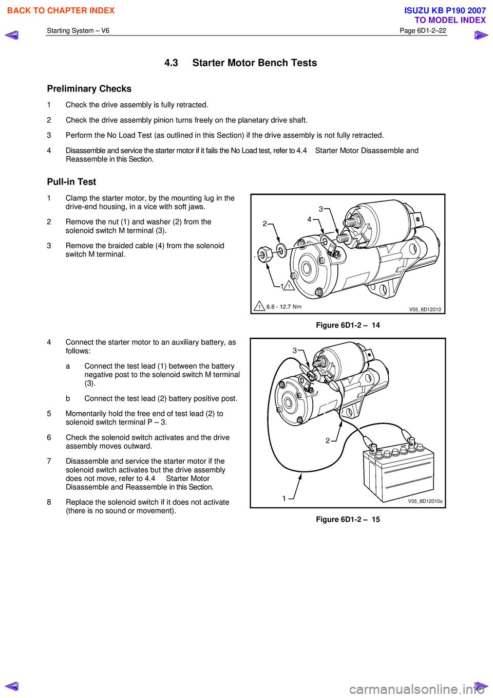
1 Clamp the starter motor, by the mounting lug in the drive-end housing, in a vice with soft jaws.
2 Remove the nut (1) and washer (2) from the solenoid switch M terminal (3).
3 Remove the braided cable (4) from the solenoid switch M terminal.
Figure 6D1-2 – 14
4 Connect the starter motor to an auxiliary battery, as follows:
a Connect the test lead (1) between the battery negative post to the solenoid switch M terminal
(3).
b Connect the test lead (2) battery positive post.
5 Momentarily hold the free end of test lead (2) to solenoid switch terminal P – 3.
6 Check the solenoid switch activates and the drive assembly moves outward.
7 Disassemble and service the starter motor if the solenoid switch activates but the drive assembly
does not move, refer to 4.4 Starter Motor
Disassemble and Reassemble in this Section.
8 Replace the solenoid switch if it does not activate (there is no sound or movement).
Figure 6D1-2 – 15
BACK TO CHAPTER INDEX
TO MODEL INDEX
ISUZU KB P190 2007
Page 3632 of 6020
Starting System – V6 Page 6D1-2–24
No Load Test
1 Clamp the starter motor securely to a test bench.
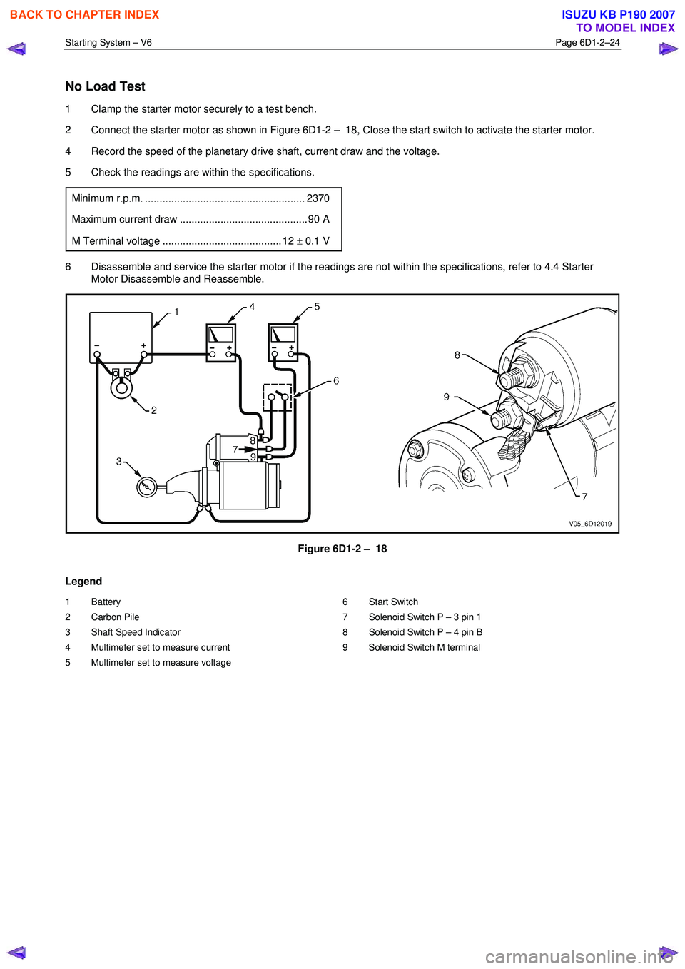
2 Connect the starter motor as shown in Figure 6D1-2 – 18, Close the start switch to activate the starter motor.
4 Record the speed of the planetary drive shaft, current draw and the voltage.
5 Check the readings are within the specifications.
Minimum r.p.m. ....................................................... 2370
Maximum current draw ............................................ 90 A
M Terminal voltage ......................................... 12 ± 0.1 V
6 Disassemble and service the starter motor if the readings are not within the specifications, refer to 4.4 Starter
Motor Disassemble and Reassemble.
Figure 6D1-2 – 18
Legend
1 Battery
2 Carbon Pile
3 Shaft Speed Indicator
4 Multimeter set to measure current
5 Multimeter set to measure voltage 6 Start Switch
7 Solenoid Switch P – 3 pin 1
8 Solenoid Switch P – 4 pin B
9 Solenoid Switch M terminal
BACK TO CHAPTER INDEX
TO MODEL INDEX
ISUZU KB P190 2007
Page 3641 of 6020
Battery Page 6D1-3–1
6D1-3
Battery – V6
ATTENTION
Before performing any service operation or other procedure described in this Section, refer to 1.1
WARNING, CAUTION and NOTES for correct workshop practices with regard to safety and/or property
damage.
1 General Information ............................................................................................................ ...................3
1.1 WARNING, CAUTION and NOTES ..................................................................................................... ................... 3
Definition of WARNING, CAUTION and NOTE Statements ............................................................................. .... 3
1.2 Battery Terminals and Cables............................................................................................................................... 4
1.3 Battery Ratings ...................................................................................................................................................... 4
Reserve Capacity ............................................................................................................... .................................... 4
Cold Cranking Amps ............................................................................................................................................. 5
Ratings.................................................................................................................................................................... 5
2 Safety Precautions .................................................................................................................................6
3 Diagnosis ................................................................................................................................................7
3.1 Diagnostic Procedures .......................................................................................................................................... 7
Introduction ............................................................................................................................................................ 7
Test Description ..................................................................................................................................................... 7
Diagnostic Table Notes ......................................................................................................................................... 7
Diagnostic Table .................................................................................................................................................... 7
3.2 Battery Inspection.................................................................................................................................................. 8
3.3 Hydrometer Test .................................................................................................................................................... 9
3.4 Load Test ...................................................................................................................... ........................................ 10
High Rate Discharge Load Test .................................................................................................. ........................ 10
Alternate Load Test ............................................................................................................................................. 11
3.5 Battery Current Draw Test...................................................................................................... ............................. 11
Test Preparation................................................................................................................................................... 11
Test Procedure ..................................................................................................................................................... 12
Fault Diagnosis .................................................................................................................................................... 12
Restore.................................................................................................................................................................. 13
4 Service Operations ...............................................................................................................................14
4.1 Battery................................................................................................................................................................... 14
Remove ......................................................................................................................... ........................................ 14
Reinstall ................................................................................................................................................................ 14
4.2 Battery Charge ................................................................................................................. .................................... 15
Safety Precautions............................................................................................................. .................................. 15
Battery Charge Procedure....................................................................................................... ............................ 15
4.3 Emergency Jump Starting Procedure .............................................................................................. .................. 16
Safety Precautions............................................................................................................................................... 16
Jump Starting Procedure ........................................................................................................ ............................ 16
4.4 Dry Charged Batteries ......................................................................................................................................... 18
Storage.................................................................................................................................................................. 18
Activation..................................................................................................................... ......................................... 18
Post Activation Tests .......................................................................................................... ................................ 18
5 Specifications .......................................................................................................................................19
BACK TO CHAPTER INDEX
TO MODEL INDEX
ISUZU KB P190 2007
Page 3643 of 6020
Battery Page 6D1-3–3
1 General Information
The vehicle is fitted with a 12 V battery located in the front right-hand corner of the engine compartment. The battery
provides:
• power for cranking the engine,
• power for a limited time when the electrical load exceeds the generator output,
• power for the accessories when the engine is not running, and
• a voltage stabilising load for the electrical system.
1.1 WARNING, CAUTION and NOTES
This Section contains various W ARNINGS, CAUTIONS and NOTE statements that you must observe carefully to reduce
the risk of death or injury during service, repair procedures or vehicle operation. Incorrect service or repair procedures
may damage the vehicle or cause operational faults. W ARNINGS, CAUTION and NOTE statements are not exhaustive.
HOLDEN LTD can not possibly warn of all the potentially hazardous consequences of failure to follow these instructions.
Definition of WARNING, CAUTION and NOTE Statements
Diagnosis and repair procedures in this Section contain both general and specific W ARNING, CAUTION and NOTE
statements. HOLDEN LTD is dedicated to the presentation of service information that helps the technician to diagnose
and repair the systems necessary for proper operation of the vehicle. Certain procedures may present a hazard to the
technician if they are not followed in the recommended manner. W ARNING, CAUTION and NOTE statements are
designed to help prevent these hazards from occurring, but not all hazards can be foreseen.
WARNING defined
A W ARNING statement immediately precedes an operating procedure or maintenance practice which, if not correctly
followed, could result in death or injury. A W ARNING statement alerts you to take necessary action or not to take a
prohibited action. If a W ARNING statement is ignored, the following consequences may occur:
• Death or injury to the technician or other personnel working on the vehicle,
• Death or injury to other people in or near the workplace area, and / or
• Death or injury to the driver / or passenger(s) of the vehicle or other people, if the vehicle has been improperly
repaired.
CAUTION defined
A CAUTION statement immediately precedes an operating procedure or maintenance practice which, if not correctly
followed, could result in damage to or destruction of equipment, or corruption of data. If a CAUTION statement is ignored,
the following consequences may occur:
• Damage to the vehicle,
• Unnecessary vehicle repairs or component replacement,
• Faulty operation or performance of any system or component being repaired,
• Damage to any system or components which depend on the proper operation of the system or component being
repaired,
• Faulty operation or performance of any systems or components which depend on the proper operation or
performance of the system or component under repair,
• Damage to fasteners, basic tools or special tools and / or
• Leakage of coolant, lubricant or other vital fluids.
NOTE defined
A NOTE statement immediately precedes or follows an operating procedure, maintenance practice or condition that
requires highlighting. A NOTE statement also emphasises necessary characteristics of a diagnostic or repair procedure.
A NOTE statement is designed to:
BACK TO CHAPTER INDEX
TO MODEL INDEX
ISUZU KB P190 2007
Page 3647 of 6020
Battery Page 6D1-3–7
3 Diagnosis
3.1 Diagnostic Procedures
Introduction
This test is used to aid in diagnosing faults with the vehicle where the battery seems to be at fault.
W ith the increased use of electronic sensors and computer control, the battery is much more than just a component used
to start a car. Low battery voltage can:
• affect the operation of the vehicle control modules and cause driveability problems, and
• cause the control modules to set diagnostic trouble codes (DTCs).
For example if a control module senses low battery voltage, it may increase fuel injector timing to increase engine rpm to
increase the generator output.
Therefore consider the state of charge of the battery any time a customer complains of a driveability related problem.
Test Description
The following numbers refer to the step numbers in the diagnostic table:
1 Checks the operator understands the safety precautions for working with batteries.
2 Checks if the vehicle is fitted with a battery of the correct specification.
3 Checks if the battery appears serviceable by performing the battery inspection procedure.
4 Checks if the battery loses charge over an extended period. If so the likely problem is excess current draw while the vehicles ignition is in the off position.
5 Checks the state of charge of the battery.
6 Checks if the battery is capable of delivering the required load by performing the load test procedure.
Diagnostic Table Notes
1 For all wiring harness fault diagnosis, refer to 8A Electrical Body & Chassis.
2 For wiring harness repairs, refer to 8A Electrical Body & Chassis.
3 Refer to 6D1 – 3 Battery – V6.
Diagnostic Table
Step Action Yes No
1
Have you read and understood the safety precautions for working with
batteries? Go to Step 2 Refer to 2
Safety Precautions
2 Check the battery fitted is the correct specification recommended for
the vehicle? Refer to 5 Specifications.
Is the battery the correct specification? Go to Step 3 Replace the battery
with the correct
specification
3 Perform the battery inspection, refer to 3.2 Battery Inspection.
Does the battery appear serviceable? Go to Step 4 Replace the battery,
refer to 4.1
Battery
4 Does the customer complain the battery loses charge if the engine is
not started for an extended period? Preform the battery
current draw test, refer to 3.5
Battery
Current Draw Test Go to Step 5
BACK TO CHAPTER INDEX
TO MODEL INDEX
ISUZU KB P190 2007
Page 3648 of 6020
Battery Page 6D1-3–8
Step Action Yes No
5
Perform the hydrometer test, refer to 3.3 Hydrometer Test.
Is the battery fully charged? Go to Step 6 Fully charge the
battery, refer to 4.2 Battery
Charge
6 Load test the battery, refer to 3.4 Load Test.
Does the battery pass the load test? Battery Serviceable.
Refer to:
6D1–1 Charging System – V6. Replace the battery,
refer to 4.1
Battery
When all diagnosis and repairs are completed, check the system for correct operation.
3.2 Battery Inspection
1 Read and obey the safety precautions for working with batteries, refer to 2 Safety Precautions.
2 Check the battery terminals and around the battery area for corrosion deposits. Remove any deposits as follows: a Scrub the area with a stiff brush.
b Treat the area with a solution of warm water and baking soda or ammonia.
c Rinse with clean water.
3 Check the battery posts, if they are loose, burned, pitted or damaged in any way replace the battery. Refer to 4.1 Battery.
4 Check the battery case, if it is cracked or damaged replace the battery. Refer to 4.1 Battery.
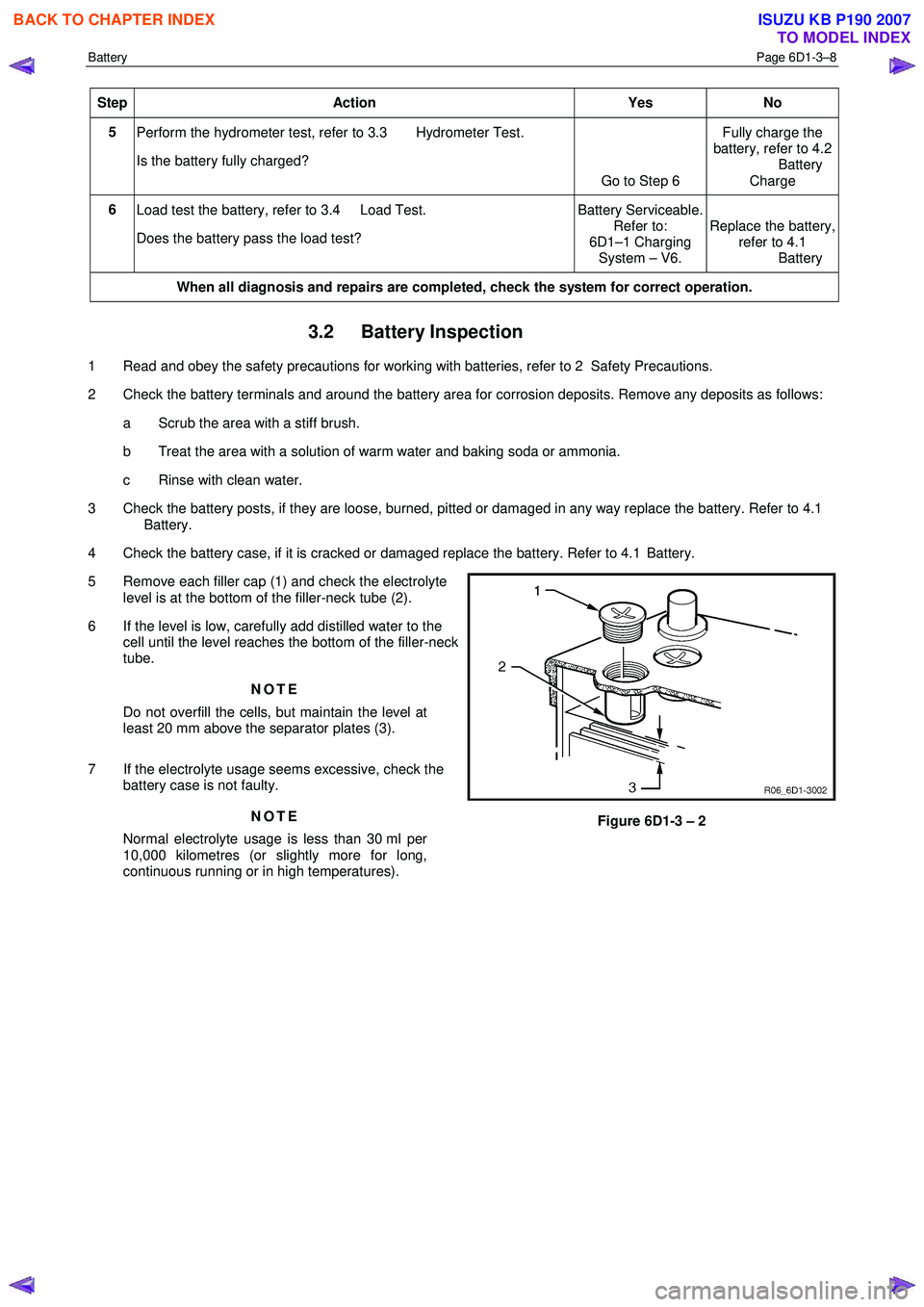
5 Remove each filler cap (1) and check the electrolyte level is at the bottom of the filler-neck tube (2).
6 If the level is low, carefully add distilled water to the cell until the level reaches the bottom of the filler-neck
tube.
NOTE
Do not overfill the cells, but maintain the level at
least 20 mm above the separator plates (3).
7 If the electrolyte usage seems excessive, check the battery case is not faulty.
NOTE
Normal electrolyte usage is less than 30 ml per
10,000 kilometres (or slightly more for long,
continuous running or in high temperatures).
Figure 6D1-3 – 2
BACK TO CHAPTER INDEX
TO MODEL INDEX
ISUZU KB P190 2007
Page 3650 of 6020
Battery Page 6D1-3–10
6 Still holding the hydrometer vertically, record the reading.
7 Put the electrolyte back into the cell.
8 Repeat steps 3 to 7 for each cell.
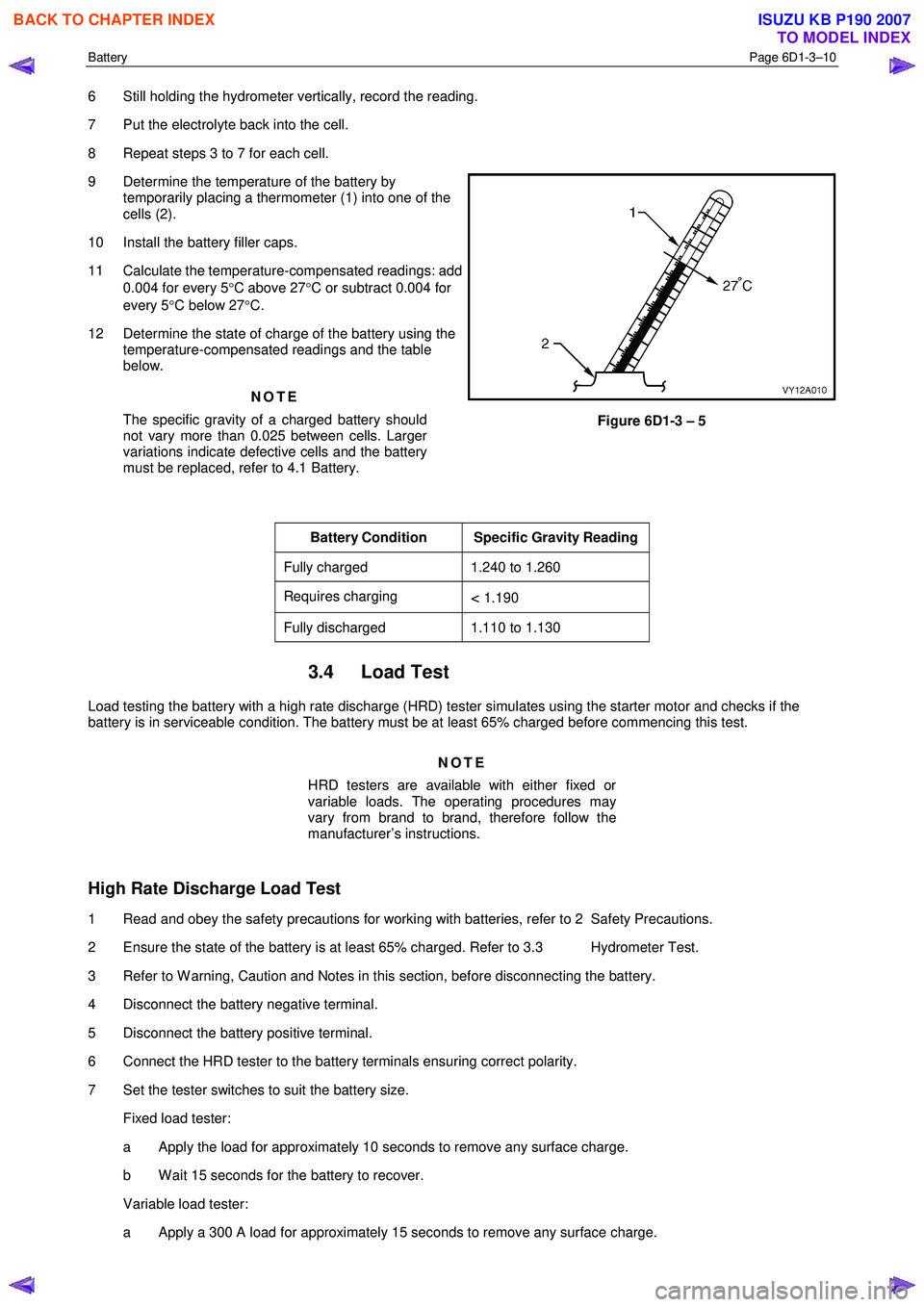
9 Determine the temperature of the battery by temporarily placing a thermometer (1) into one of the
cells (2).
10 Install the battery filler caps.
11 Calculate the temperature-compensated readings: add 0.004 for every 5 °C above 27 °C or subtract 0.004 for
every 5 °C below 27 °C.
12 Determine the state of charge of the battery using the temperature-compensated readings and the table
below.
NOTE
The specific gravity of a charged battery should
not vary more than 0.025 between cells. Larger
variations indicate defective cells and the battery
must be replaced, refer to 4.1 Battery.
Figure 6D1-3 – 5
Battery Condition Specific Gravity Reading
Fully charged 1.240 to 1.260
Requires charging < 1.190
Fully discharged 1.110 to 1.130
3.4 Load Test
Load testing the battery with a high rate discharge (HRD) tester simulates using the starter motor and checks if the
battery is in serviceable condition. The battery must be at least 65% charged before commencing this test.
NOTE
HRD testers are available with either fixed or
variable loads. The operating procedures may
vary from brand to brand, therefore follow the
manufacturer’s instructions.
High Rate Discharge Load Test
1 Read and obey the safety precautions for working with batteries, refer to 2 Safety Precautions.
2 Ensure the state of the battery is at least 65% charged. Refer to 3.3 Hydrometer Test.
3 Refer to W arning, Caution and Notes in this section, before disconnecting the battery.
4 Disconnect the battery negative terminal.
5 Disconnect the battery positive terminal.
6 Connect the HRD tester to the battery terminals ensuring correct polarity.
7 Set the tester switches to suit the battery size. Fixed load tester:
a Apply the load for approximately 10 seconds to remove any surface charge.
b W ait 15 seconds for the battery to recover.
Variable load tester:
a Apply a 300 A load for approximately 15 seconds to remove any surface charge.
BACK TO CHAPTER INDEX
TO MODEL INDEX
ISUZU KB P190 2007