2007 ISUZU KB P190 service
[x] Cancel search: servicePage 3609 of 6020
Starting System – V6 Page 6D1-2–1
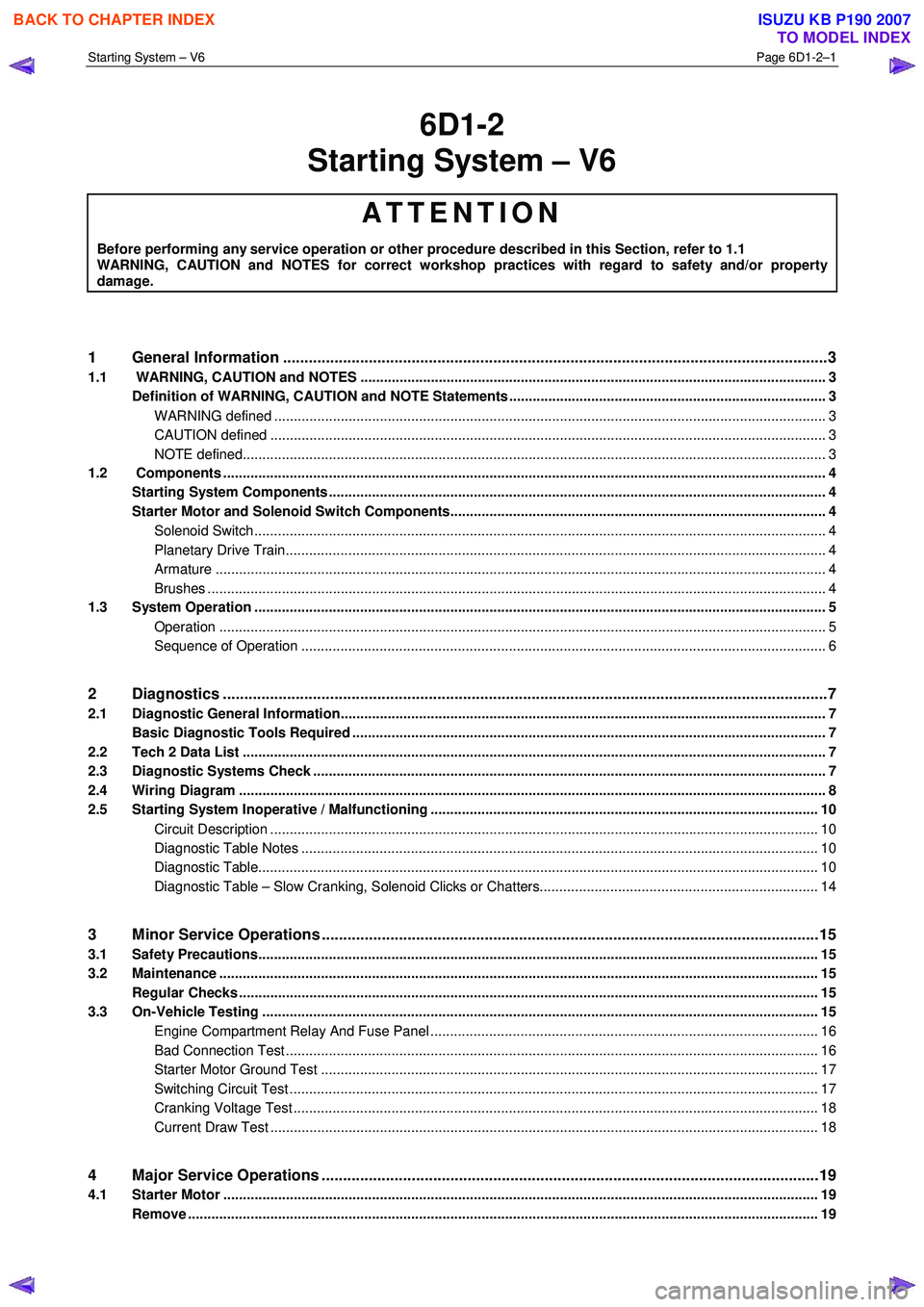
6D1-2
Starting System – V6
ATTENTION
Before performing any service operation or other procedure described in this Section, refer to 1.1
WARNING, CAUTION and NOTES for correct workshop practices with regard to safety and/or property
damage.
1 General Information ............................................................................................................ ...................3
1.1 WARNING, CAUTION and NOTES .................................................................................................... ................... 3
Definition of WARNING, CAUTION and NOTE Statements ............................................................................. .... 3
WARNING defined ............................................................................................................................................. 3
CAUTION defined .............................................................................................................................................. 3
NOTE defined..................................................................................................................................................... 3
1.2 Components .......................................................................................................................................................... 4
Starting System Components ............................................................................................................................... 4
Starter Motor and Solenoid Switch Components................................................................................... ............. 4
Solenoid Switch.................................................................................................................................................. 4
Planetary Drive Train.......................................................................................................... ................................ 4
Armature ............................................................................................................................................................ 4
Brushes .............................................................................................................................................................. 4
1.3 System Operation .................................................................................................................................................. 5
Operation ...................................................................................................................... ..................................... 5
Sequence of Operation .......................................................................................................... ............................ 6
2 Diagnostics .............................................................................................................................................7
2.1 Diagnostic General Information............................................................................................................................ 7
Basic Diagnostic Tools Required ......................................................................................................................... 7
2.2 Tech 2 Data List ............................................................................................................... ...................................... 7
2.3 Diagnostic Systems Check ....................................................................................................... ............................ 7
2.4 Wiring Diagram ...................................................................................................................................................... 8
2.5 Starting System Inoperative / Malfunctioning ................................................................................... ................ 10
Circuit Description ............................................................................................................................................ 10
Diagnostic Table Notes ......................................................................................................... ........................... 10
Diagnostic Table............................................................................................................................................... 10
Diagnostic Table – Slow Cranking, Solenoid Clicks or Chatters.................................................................. ..... 14
3 Minor Service Operations ....................................................................................................................15
3.1 Safety Precautions............................................................................................................................................... 15
3.2 Maintenance ......................................................................................................................................................... 15
Regular Checks ................................................................................................................. ................................... 15
3.3 On-Vehicle Testing ............................................................................................................. ................................. 15
Engine Compartment Relay And Fuse Panel ........................................................................................ ........... 16
Bad Connection Test ........................................................................................................................................ 16
Starter Motor Ground Test ...................................................................................................... ......................... 17
Switching Circuit Test ....................................................................................................................................... 17
Cranking Voltage Test .......................................................................................................... ............................ 18
Current Draw Test ............................................................................................................................................ 18
4 Major Service Operations ....................................................................................................................19
4.1 Starter Motor ........................................................................................................................................................ 19
Remove ................................................................................................................................................................. 19
BACK TO CHAPTER INDEX
TO MODEL INDEX
ISUZU KB P190 2007
Page 3611 of 6020
Starting System – V6 Page 6D1-2–3
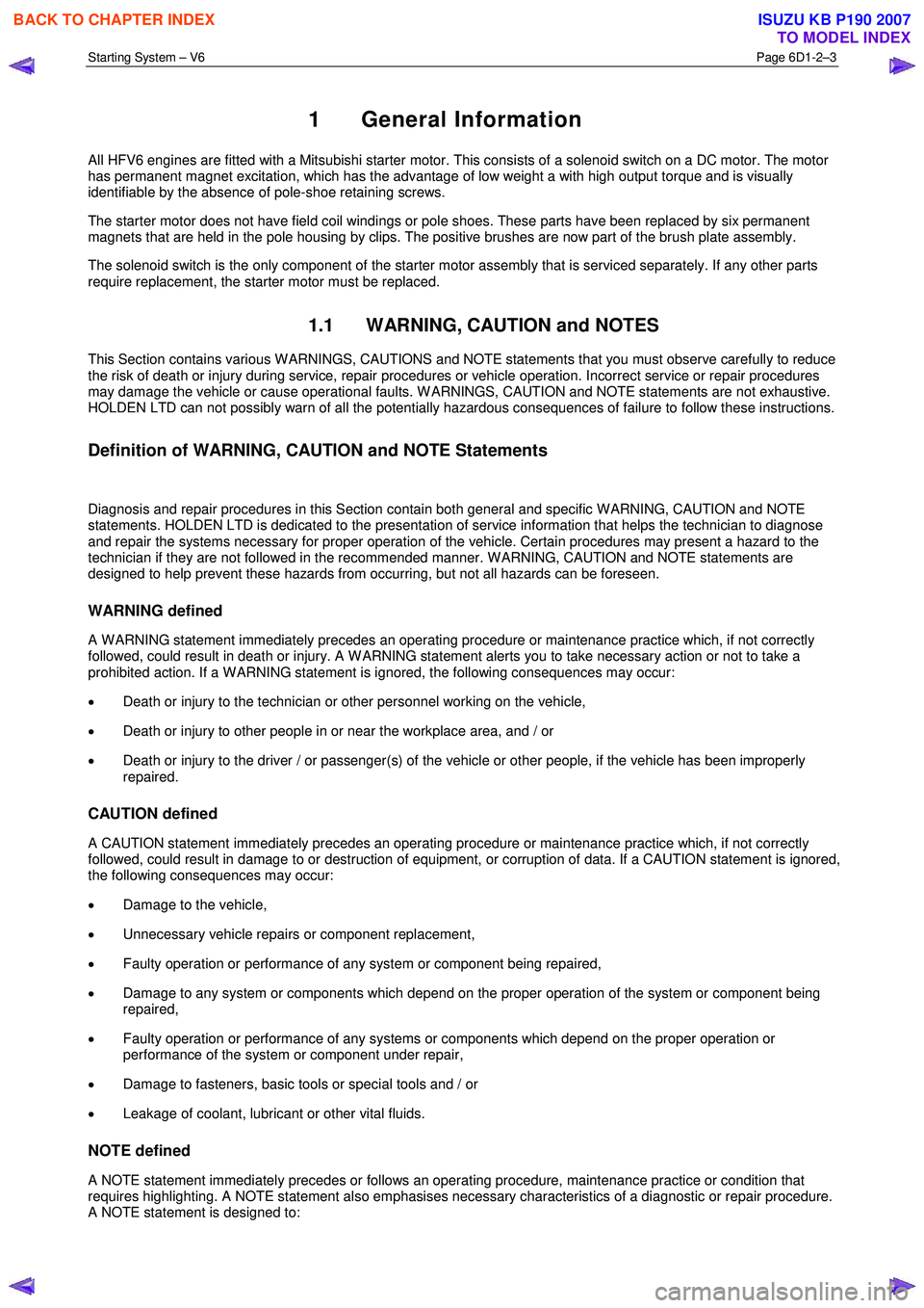
1 General Information
All HFV6 engines are fitted with a Mitsubishi starter motor. This consists of a solenoid switch on a DC motor. The motor
has permanent magnet excitation, which has the advantage of low weight a with high output torque and is visually
identifiable by the absence of pole-shoe retaining screws.
The starter motor does not have field coil windings or pole shoes. These parts have been replaced by six permanent
magnets that are held in the pole housing by clips. The positive brushes are now part of the brush plate assembly.
The solenoid switch is the only component of the starter motor assembly that is serviced separately. If any other parts
require replacement, the starter motor must be replaced.
1.1 WARNING, CAUTION and NOTES
This Section contains various W ARNINGS, CAUTIONS and NOTE statements that you must observe carefully to reduce
the risk of death or injury during service, repair procedures or vehicle operation. Incorrect service or repair procedures
may damage the vehicle or cause operational faults. W ARNINGS, CAUTION and NOTE statements are not exhaustive.
HOLDEN LTD can not possibly warn of all the potentially hazardous consequences of failure to follow these instructions.
Definition of WARNING, CAUTION and NOTE Statements
Diagnosis and repair procedures in this Section contain both general and specific W ARNING, CAUTION and NOTE
statements. HOLDEN LTD is dedicated to the presentation of service information that helps the technician to diagnose
and repair the systems necessary for proper operation of the vehicle. Certain procedures may present a hazard to the
technician if they are not followed in the recommended manner. W ARNING, CAUTION and NOTE statements are
designed to help prevent these hazards from occurring, but not all hazards can be foreseen.
WARNING defined
A W ARNING statement immediately precedes an operating procedure or maintenance practice which, if not correctly
followed, could result in death or injury. A W ARNING statement alerts you to take necessary action or not to take a
prohibited action. If a W ARNING statement is ignored, the following consequences may occur:
• Death or injury to the technician or other personnel working on the vehicle,
• Death or injury to other people in or near the workplace area, and / or
• Death or injury to the driver / or passenger(s) of the vehicle or other people, if the vehicle has been improperly
repaired.
CAUTION defined
A CAUTION statement immediately precedes an operating procedure or maintenance practice which, if not correctly
followed, could result in damage to or destruction of equipment, or corruption of data. If a CAUTION statement is ignored,
the following consequences may occur:
• Damage to the vehicle,
• Unnecessary vehicle repairs or component replacement,
• Faulty operation or performance of any system or component being repaired,
• Damage to any system or components which depend on the proper operation of the system or component being
repaired,
• Faulty operation or performance of any systems or components which depend on the proper operation or
performance of the system or component under repair,
• Damage to fasteners, basic tools or special tools and / or
• Leakage of coolant, lubricant or other vital fluids.
NOTE defined
A NOTE statement immediately precedes or follows an operating procedure, maintenance practice or condition that
requires highlighting. A NOTE statement also emphasises necessary characteristics of a diagnostic or repair procedure.
A NOTE statement is designed to:
BACK TO CHAPTER INDEX
TO MODEL INDEX
ISUZU KB P190 2007
Page 3618 of 6020
Starting System – V6 Page 6D1-2–10
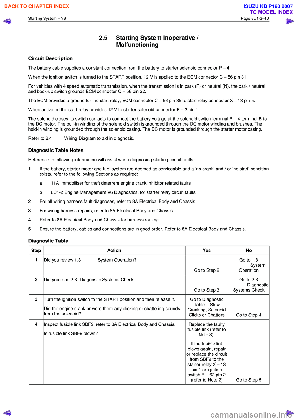
2.5 Starting System Inoperative /
Malfunctioning
Circuit Description
The battery cable supplies a constant connection from the battery to starter solenoid connector P – 4.
W hen the ignition switch is turned to the START position, 12 V is applied to the ECM connector C – 56 pin 31.
For vehicles with 4 speed automatic transmission, when the transmission is in park (P) or neutral (N), the park / neutral
and back-up switch grounds ECM connector C – 56 pin 32.
The ECM provides a ground for the start relay, ECM connector C – 56 pin 35 to start relay connector X – 13 pin 5.
W hen activated the start relay provides 12 V to starter solenoid connector P – 3 pin 1.
The solenoid closes its switch contacts to connect the battery voltage at the solenoid switch terminal P – 4 terminal B to
the DC motor. The pull-in winding of the solenoid switch is grounded through the DC motor winding and brushes. The
hold-in winding is grounded through the solenoid casing. The DC motor is grounded through the starter motor casing.
Refer to 2.4 W iring Diagram to aid in diagnosis.
Diagnostic Table Notes
Reference to following information will assist when diagnosing starting circuit faults:
1 If the battery, starter motor and fuel system are deemed as serviceable and a ‘no crank’ and / or ‘no start’ condition exists, refer to the following Sections as required:
a 11A Immobiliser for theft deterrent engine crank inhibitor related faults
b 6C1-2 Engine Management V6 Diagnostics, for starter relay circuit faults
2 For all wiring harness fault diagnoses, refer to 8A Electrical Body and Chassis.
3 For wiring harness repairs, refer to 8A Electrical Body and Chassis.
4 Refer to 8A Electrical Body and Chassis for harness routing.
5 Ensure the battery, cables and connections are in good order. Refer to 8A Electrical Body and Chassis.
Diagnostic Table
Step Action Yes No
1
Did you review 1.3 System Operation?
Go to Step 2 Go to 1.3
System
Operation
2 Did you read 2.3 Diagnostic Systems Check
Go to Step 3 Go to 2.3
Diagnostic Systems Check
3 Turn the ignition switch to the START position and then release it.
Did the engine crank or were there any clicking or chattering sounds
from the solenoid? Go to Diagnostic
Table – Slow
Cranking, Solenoid Clicks or Chatters Go to Step 4
4 Inspect fusible link SBF9, refer to 8A Electrical Body and Chassis.
Is fusible link SBF9 blown? Replace the faulty
fusible link (refer to
Note 3).
If the fusible link
blows again, repair
or replace the circuit from SBF9 to the
starter relay X – 13 pin 1 or ignition
switch B – 62 pin 2 (refer to Note 2) Go to Step 5
BACK TO CHAPTER INDEX
TO MODEL INDEX
ISUZU KB P190 2007
Page 3620 of 6020
Starting System – V6 Page 6D1-2–12
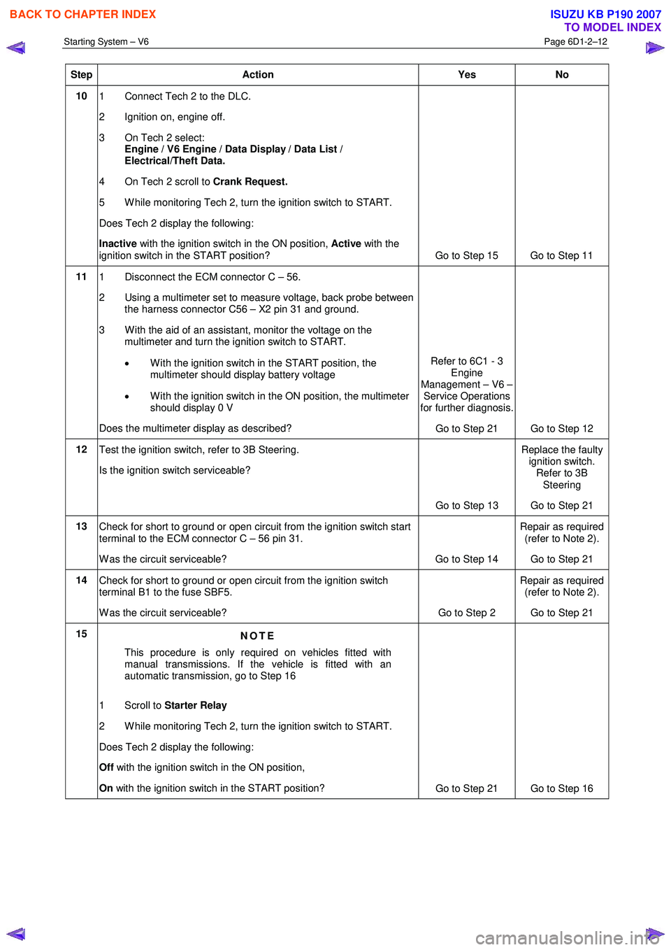
Step Action Yes No
10
1 Connect Tech 2 to the DLC.
2 Ignition on, engine off.
3 On Tech 2 select: Engine / V6 Engine / Data Display / Data List /
Electrical/Theft Data.
4 On Tech 2 scroll to Crank Request.
5 W hile monitoring Tech 2, turn the ignition switch to START.
Does Tech 2 display the following:
Inactive with the ignition switch in the ON position, Active with the
ignition switch in the START position? Go to Step 15 Go to Step 11
11 1 Disconnect the ECM connector C – 56.
2 Using a multimeter set to measure voltage, back probe between the harness connector C56 – X2 pin 31 and ground.
3 W ith the aid of an assistant, monitor the voltage on the multimeter and turn the ignition switch to START.
• W ith the ignition switch in the START position, the
multimeter should display battery voltage
• W ith the ignition switch in the ON position, the multimeter
should display 0 V
Does the multimeter display as described? Refer to 6C1 - 3
Engine
Management – V6 – Service Operations
for further diagnosis.
Go to Step 21 Go to Step 12
12 Test the ignition switch, refer to 3B Steering.
Is the ignition switch serviceable?
Go to Step 13 Replace the faulty
ignition switch. Refer to 3B
Steering
Go to Step 21
13 Check for short to ground or open circuit from the ignition switch start
terminal to the ECM connector C – 56 pin 31.
W as the circuit serviceable? Go to Step 14 Repair as required
(refer to Note 2).
Go to Step 21
14 Check for short to ground or open circuit from the ignition switch
terminal B1 to the fuse SBF5.
W as the circuit serviceable? Go to Step 2 Repair as required
(refer to Note 2).
Go to Step 21
15 NOTE
This procedure is only required on vehicles fitted with
manual transmissions. If the vehicle is fitted with an
automatic transmission, go to Step 16
1 Scroll to Starter Relay
2 W hile monitoring Tech 2, turn the ignition switch to START.
Does Tech 2 display the following:
Off with the ignition switch in the ON position,
On with the ignition switch in the START position?
Go to Step 21 Go to Step 16
BACK TO CHAPTER INDEX
TO MODEL INDEX
ISUZU KB P190 2007
Page 3621 of 6020
Starting System – V6 Page 6D1-2–13
Step Action Yes No
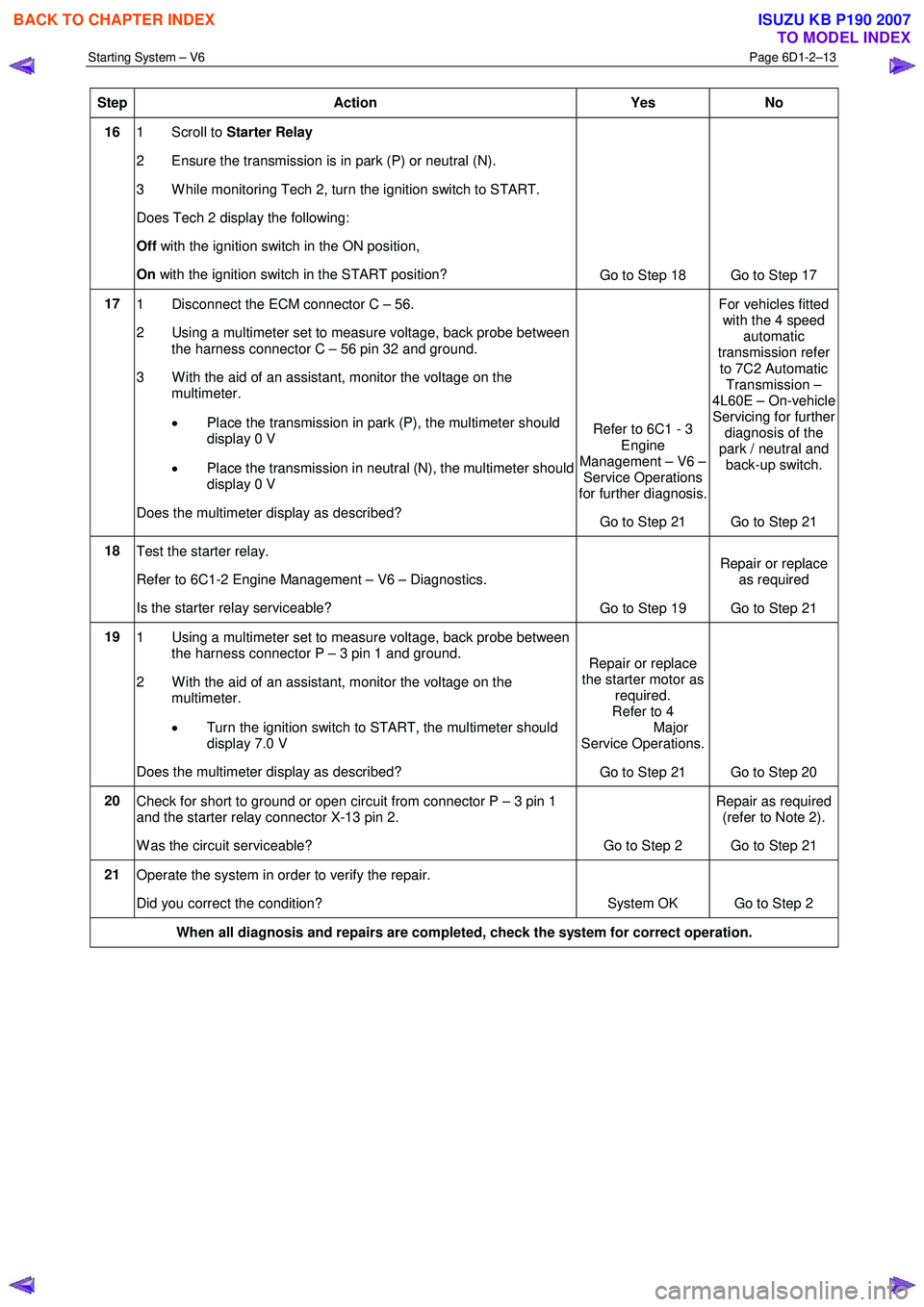
16 1 Scroll to Starter Relay
2 Ensure the transmission is in park (P) or neutral (N).
3 W hile monitoring Tech 2, turn the ignition switch to START.
Does Tech 2 display the following:
Off with the ignition switch in the ON position,
On with the ignition switch in the START position?
Go to Step 18 Go to Step 17
17 1 Disconnect the ECM connector C – 56.
2 Using a multimeter set to measure voltage, back probe between the harness connector C – 56 pin 32 and ground.
3 W ith the aid of an assistant, monitor the voltage on the multimeter.
• Place the transmission in park (P), the multimeter should
display 0 V
• Place the transmission in neutral (N), the multimeter should
display 0 V
Does the multimeter display as described? Refer to 6C1 - 3
Engine
Management – V6 – Service Operations
for further diagnosis.
Go to Step 21 For vehicles fitted
with the 4 speed automatic
transmission refer
to 7C2 Automatic Transmission –
4L60E – On-vehicle Servicing for further
diagnosis of the
park / neutral and back-up switch.
Go to Step 21
18 Test the starter relay.
Refer to 6C1-2 Engine Management – V6 – Diagnostics.
Is the starter relay serviceable? Go to Step 19 Repair or replace
as required
Go to Step 21
19 1 Using a multimeter set to measure voltage, back probe between
the harness connector P – 3 pin 1 and ground.
2 W ith the aid of an assistant, monitor the voltage on the multimeter.
• Turn the ignition switch to START, the multimeter should
display 7.0 V
Does the multimeter display as described? Repair or replace
the starter motor as required.
Refer to 4
Major
Service Operations.
Go to Step 21 Go to Step 20
20 Check for short to ground or open circuit from connector P – 3 pin 1
and the starter relay connector X-13 pin 2.
W as the circuit serviceable? Go to Step 2 Repair as required
(refer to Note 2).
Go to Step 21
21 Operate the system in order to verify the repair.
Did you correct the condition? System OK Go to Step 2
When all diagnosis and repairs are completed, check the system for correct operation.
BACK TO CHAPTER INDEX
TO MODEL INDEX
ISUZU KB P190 2007
Page 3622 of 6020
Starting System – V6 Page 6D1-2–14
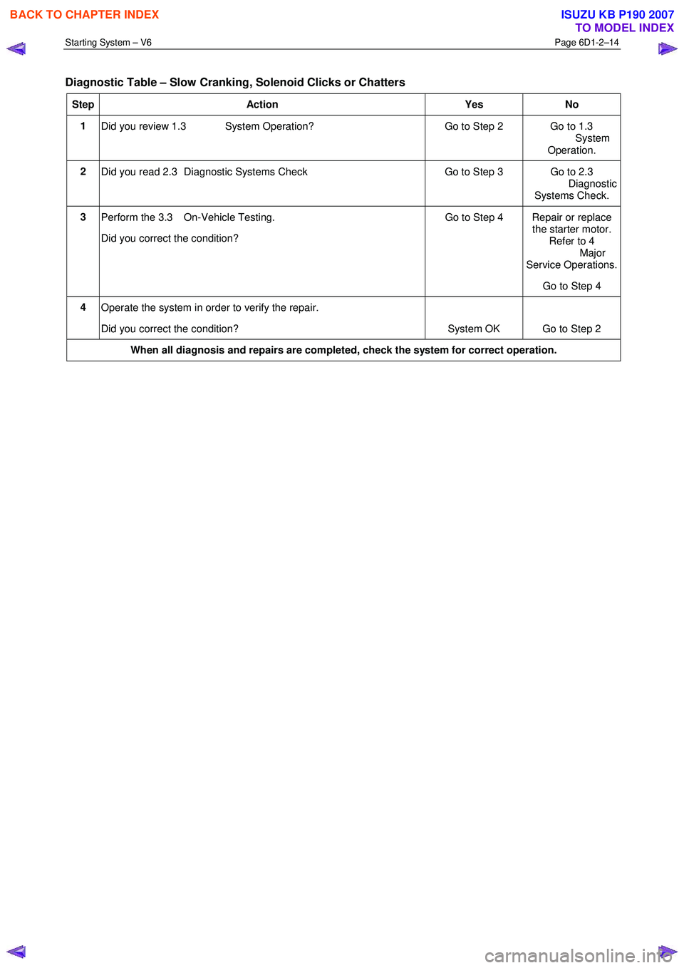
Diagnostic Table – Slow Cranking, Solenoid Clicks or Chatters
Step Action Yes No
1
Did you review 1.3 System Operation? Go to Step 2 Go to 1.3
System
Operation.
2 Did you read 2.3 Diagnostic Systems Check Go to Step 3 Go to 2.3
Diagnostic Systems Check.
3 Perform the 3.3 On-Vehicle Testing.
Did you correct the condition? Go to Step 4 Repair or replace
the starter motor.
Refer to 4
Major
Service Operations.
Go to Step 4
4 Operate the system in order to verify the repair.
Did you correct the condition? System OK Go to Step 2
When all diagnosis and repairs are completed, check the system for correct operation.
BACK TO CHAPTER INDEX
TO MODEL INDEX
ISUZU KB P190 2007
Page 3623 of 6020
Starting System – V6 Page 6D1-2–15
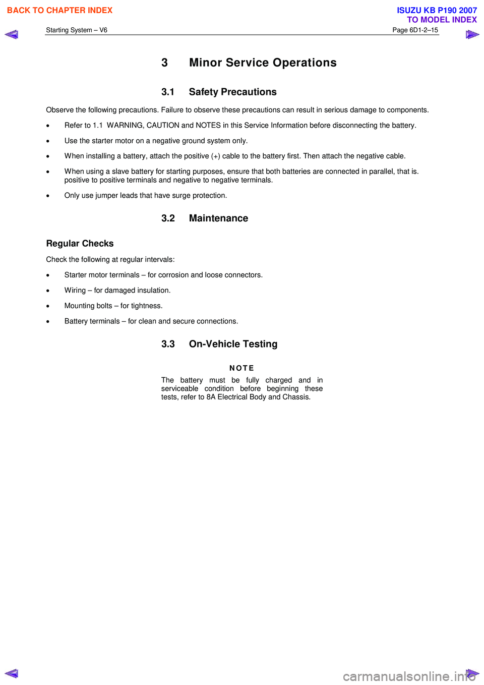
3 Minor Service Operations
3.1 Safety Precautions
Observe the following precautions. Failure to observe these precautions can result in serious damage to components.
• Refer to 1.1 W ARNING, CAUTION and NOTES in this Service Information before disconnecting the battery.
• Use the starter motor on a negative ground system only.
• W hen installing a battery, attach the positive (+) cable to the battery first. Then attach the negative cable.
• W hen using a slave battery for starting purposes, ensure that both batteries are connected in parallel, that is.
positive to positive terminals and negative to negative terminals.
• Only use jumper leads that have surge protection.
3.2 Maintenance
Regular Checks
Check the following at regular intervals:
• Starter motor terminals – for corrosion and loose connectors.
• W iring – for damaged insulation.
• Mounting bolts – for tightness.
• Battery terminals – for clean and secure connections.
3.3 On-Vehicle Testing
NOTE
The battery must be fully charged and in
serviceable condition before beginning these
tests, refer to 8A Electrical Body and Chassis.
BACK TO CHAPTER INDEX
TO MODEL INDEX
ISUZU KB P190 2007
Page 3626 of 6020
Starting System – V6 Page 6D1-2–18
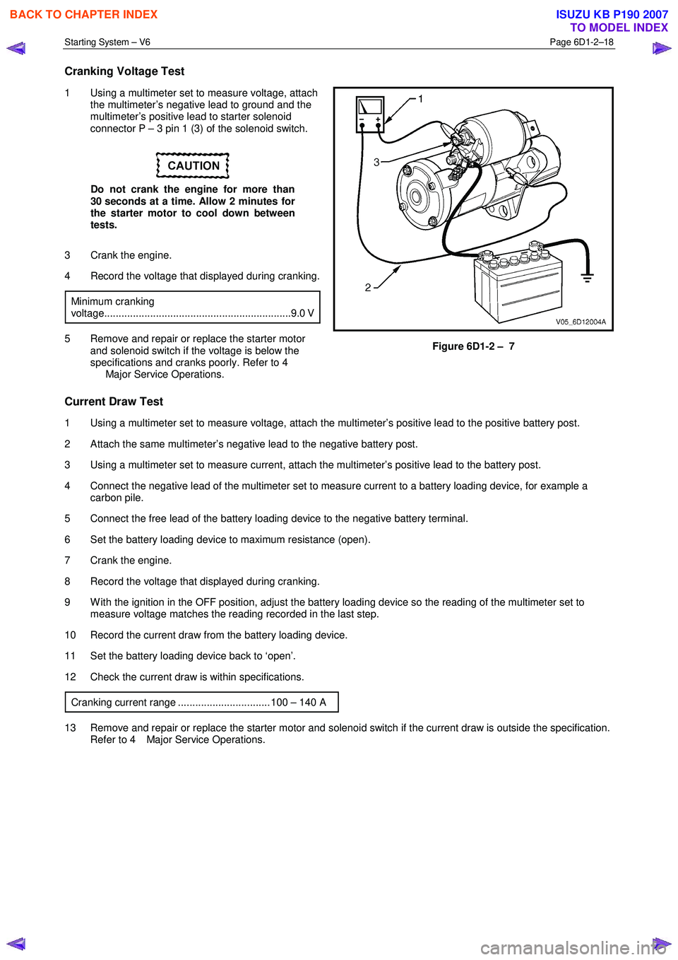
Cranking Voltage Test
1 Using a multimeter set to measure voltage, attach
the multimeter’s negative lead to ground and the
multimeter’s positive lead to starter solenoid
connector P – 3 pin 1 (3) of the solenoid switch.
Do not crank the engine for more than
30 seconds at a time. Allow 2 minutes for
the starter motor to cool down between
tests.
3 Crank the engine.
4 Record the voltage that displayed during cranking.
Minimum cranking
voltage.................................................................9.0 V
5 Remove and repair or replace the starter motor and solenoid switch if the voltage is below the
specifications and cranks poorly. Refer to 4
Major Service Operations. Figure 6D1-2 – 7
Current Draw Test
1 Using a multimeter set to measure voltage, attach the multimeter’s positive lead to the positive battery post.
2 Attach the same multimeter’s negative lead to the negative battery post.
3 Using a multimeter set to measure current, attach the multimeter’s positive lead to the battery post.
4 Connect the negative lead of the multimeter set to measure current to a battery loading device, for example a carbon pile.
5 Connect the free lead of the battery loading device to the negative battery terminal.
6 Set the battery loading device to maximum resistance (open).
7 Crank the engine.
8 Record the voltage that displayed during cranking.
9 W ith the ignition in the OFF position, adjust the battery loading device so the reading of the multimeter set to measure voltage matches the reading recorded in the last step.
10 Record the current draw from the battery loading device.
11 Set the battery loading device back to ‘open’.
12 Check the current draw is within specifications.
Cranking current range ................................ 100 – 140 A
13 Remove and repair or replace the starter motor and solenoid switch if the current draw is outside the specification. Refer to 4 Major Service Operations.
BACK TO CHAPTER INDEX
TO MODEL INDEX
ISUZU KB P190 2007