2007 ISUZU KB P190 service
[x] Cancel search: servicePage 3652 of 6020
Battery Page 6D1-3–12
9 Lock the doors and activate the theft deterrent system to arm the vehicle.
10 If the multimeter contains fuses, check they are serviceable.
Test Procedure
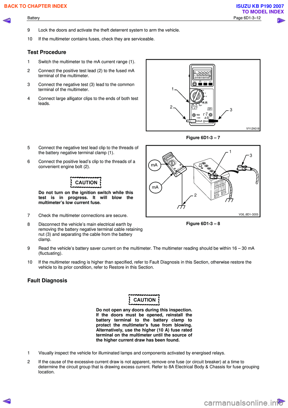
1 Switch the multimeter to the mA current range (1).
2 Connect the positive test lead (2) to the fused mA terminal of the multimeter.
3 Connect the negative test (3) lead to the common terminal of the multimeter.
4 Connect large alligator clips to the ends of both test leads.
Figure 6D1-3 – 7
5 Connect the negative test lead clip to the threads of the battery negative terminal clamp (1).
6 Connect the positive lead’s clip to the threads of a convenient engine bolt (2).
Do not turn on the ignition switch while this
test is in progress. It will blow the
multimeter’s low current fuse.
7 Check the multimeter connections are secure.
8 Disconnect the vehicle’s main electrical earth by removing the battery negative terminal cable retaining
nut (3) and separating the cable from the battery
clamp.
Figure 6D1-3 – 8
9 Read the vehicle’s battery saver current on the multimeter. The multimeter reading should be within 16 – 30 mA (fluctuating).
10 If the multimeter reading is higher than specified, refer to Fault Diagnosis in this Section, otherwise restore the vehicle to its prior condition, refer to Restore in this Section.
Fault Diagnosis
Do not open any doors during this inspection.
If the doors must be opened, reinstall the
battery terminal to the battery clamp to
protect the multimeter's fuse from blowing.
Alternatively, use the higher (10 A) fuse rated
terminal on the multimeter until the source of
the higher current draw has been found.
1 Visually inspect the vehicle for illuminated lamps and components activated by energised relays.
2 If the cause of the excessive current draw is not apparent, remove one fuse (or circuit breaker) at a time to determine the circuit group that is drawing excess current. Refer to 8A Electrical Body & Chassis for fuse grouping
location.
BACK TO CHAPTER INDEX
TO MODEL INDEX
ISUZU KB P190 2007
Page 3654 of 6020
Battery Page 6D1-3–14
4 Service Operations
4.1 Battery
Remove
Disconnection of the battery affects certain
vehicle electronic systems. Refer to 1.1
WARNING, CAUTION and NOTES before
disconnecting the battery.
1 Read and obey the safety precautions for working with batteries, refer to 2 Safety Precautions.
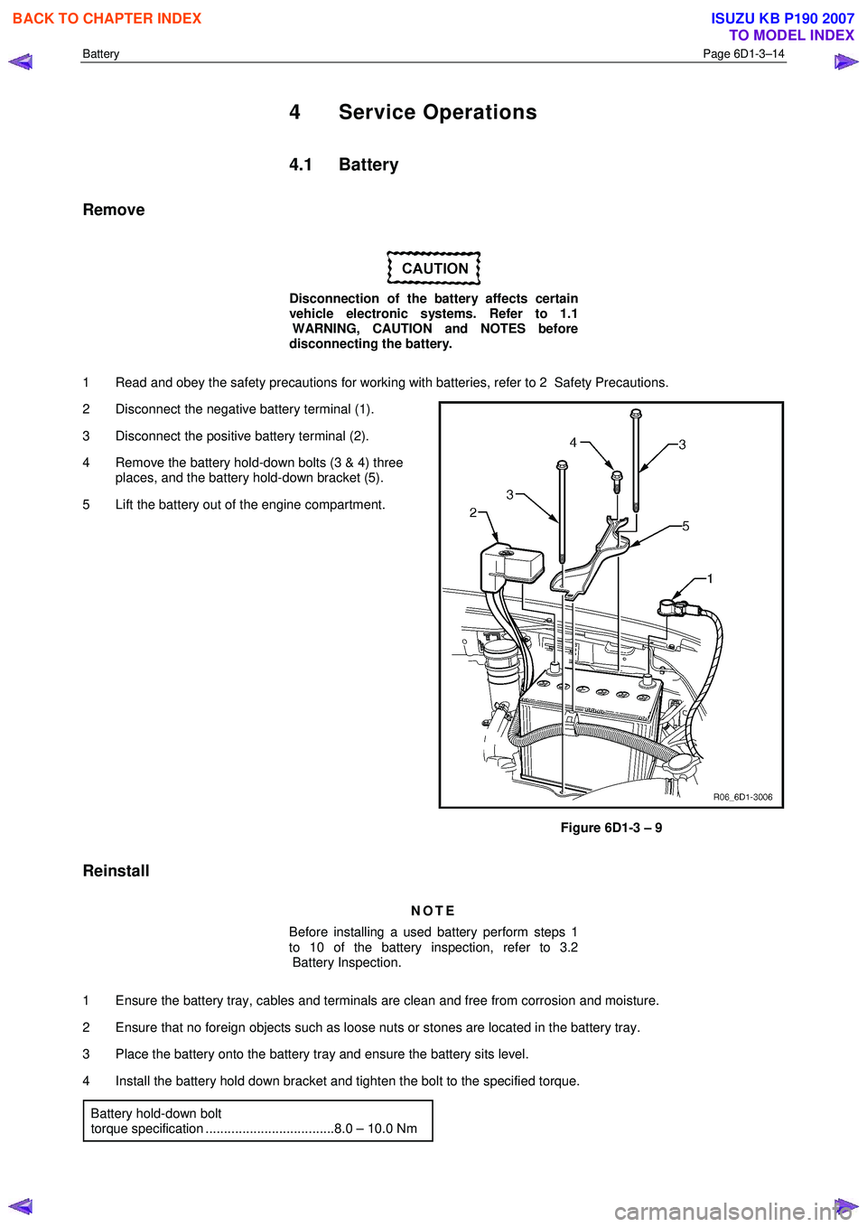
2 Disconnect the negative battery terminal (1).
3 Disconnect the positive battery terminal (2).
4 Remove the battery hold-down bolts (3 & 4) three places, and the battery hold-down bracket (5).
5 Lift the battery out of the engine compartment.
Figure 6D1-3 – 9
Reinstall
NOTE
Before installing a used battery perform steps 1
to 10 of the battery inspection, refer to 3.2
Battery Inspection.
1 Ensure the battery tray, cables and terminals are clean and free from corrosion and moisture.
2 Ensure that no foreign objects such as loose nuts or stones are located in the battery tray.
3 Place the battery onto the battery tray and ensure the battery sits level.
4 Install the battery hold down bracket and tighten the bolt to the specified torque. Battery hold-down bolt
torque specification ...................................8.0 – 10.0 Nm
BACK TO CHAPTER INDEX
TO MODEL INDEX
ISUZU KB P190 2007
Page 3658 of 6020
Battery Page 6D1-3–18
4.4 Dry Charged Batteries
Storage
Dry charged batteries are fully charged when manufactured and contain no electrolyte until activated. The dry charged
can be stored indefinitely with no servicing until activated.
Activation
1 Remove the battery filler caps.
2 Add 1.265 specific gravity electrolyte to each cell to the correct level.
3 W ait several minutes.
4 Check the electrolyte level and add more electrolyte (not water) as required. After a dry charged battery is activated, it becomes a wet battery.
Post Activation Tests
Although a dry charged battery can be put into service immediately after activation, the following tests are recommended:
1 Check the voltage of the battery after adding the electrolyte.
2 If the reading is less than 10 V, replace the battery.
3 Check the specific gravity of the electrolyte in each cell, refer to 3.3 Hydrometer Test.
4 If any reading shows more than a 0.030 drop from the initial electrolyte reading, slow-charge the battery before use. Refer to 4.2 Battery Charge.
5 Check the cells for violent gassing. If violent gassing is detected evenly across all cells, slow-charge the battery before use. If violent gassing is not even across all cells, replace the battery.
BACK TO CHAPTER INDEX
TO MODEL INDEX
ISUZU KB P190 2007
Page 3662 of 6020
Powertrain Interface Module – V6 Page 6E1–1
6E1
Powertrain Interface Module – V6
ATTENTION
Before performing any service operation or other procedure described in this Section, refer to 1.2 Warning
Caution and Notes for correct workshop practices with regard to safety and / or property damage.
1 General Information ............................................................................................................ ...................6
1.1 General Description ............................................................................................................ ................................... 6
Serial Data Communication .................................................................................................................................. 6
Serial Data Layout.................................................................................................................................................. 8
1.2 Warning Caution and Notes .................................................................................................................................. 8
Definition of WARNING, CAUTION and NOTE Statements ............................................................................. .... 8
2 Component Location............................................................................................................................10
2.1 Engine Compartment............................................................................................................. .............................. 10
2.2 Interior................................................................................................................................................................... 11
3 Component Description and Operation ............................................................................................ .12
3.1 Powertrain Interface Module ............................................................................................................................... 12
3.2 Powertrain Interface Module Gateway Components ................................................................................. ....... 13
Engine Control Module........................................................................................................................................ 13
Immobiliser Control Unit ..................................................................................................................................... 13
Automatic Transmission Control Module .......................................................................................... ................ 13
3.3 Powertrain Interface Module Direct Input Switches.............................................................................. ............ 14
Cruise Control Switch.......................................................................................................................................... 14
Power Mode Switch – Automatic Transmission..................................................................................... ........... 14
3rd Start Switch – Automatic Transmission ....................................................................................................... 14
4 Diagnostics ...........................................................................................................................................15
4.1 Diagnostic General Descriptions................................................................................................ ........................ 15
Diagnostic Trouble Code (DTC) Tables........................................................................................... ................... 15
Diagnostic Trouble Codes (DTCs) ...................................................................................................................... 15
Tech 2 PIM Diagnostic Tests............................................................................................................................... 16
5 GM LAN Serial Communication Circuit ............................................................................................ ..17
6 Wiring Diagram and Connector Chart ................................................................................................18
6.1 Wiring Diagrams .................................................................................................................................................. 18
6.2 Connector Chart................................................................................................................................................... 20
6.3 Connector Information .......................................................................................................... .............................. 21
PIM Connector Pin Specifications ............................................................................................... ....................... 21
7 Diagnostics Starting Point ..................................................................................................................24
7.1 Diagnostic Requirements, Precautions and Preliminary Checks .................................................................... 24
Basic Knowledge Required ................................................................................................................................. 24
Basic Diagnostic Tools Required ................................................................................................ ....................... 24
Diagnostic Precautions ....................................................................................................................................... 24
Preliminary Checks.............................................................................................................................................. 25
7.2 Diagnostic System Check ........................................................................................................ ........................... 25
7.3 Powertrain Interface Module – Module Communication Check Failure Diagnostic Table............................. 27
BACK TO CHAPTER INDEX
TO MODEL INDEX
ISUZU KB P190 2007
Page 3665 of 6020
Powertrain Interface Module – V6 Page 6E1–4
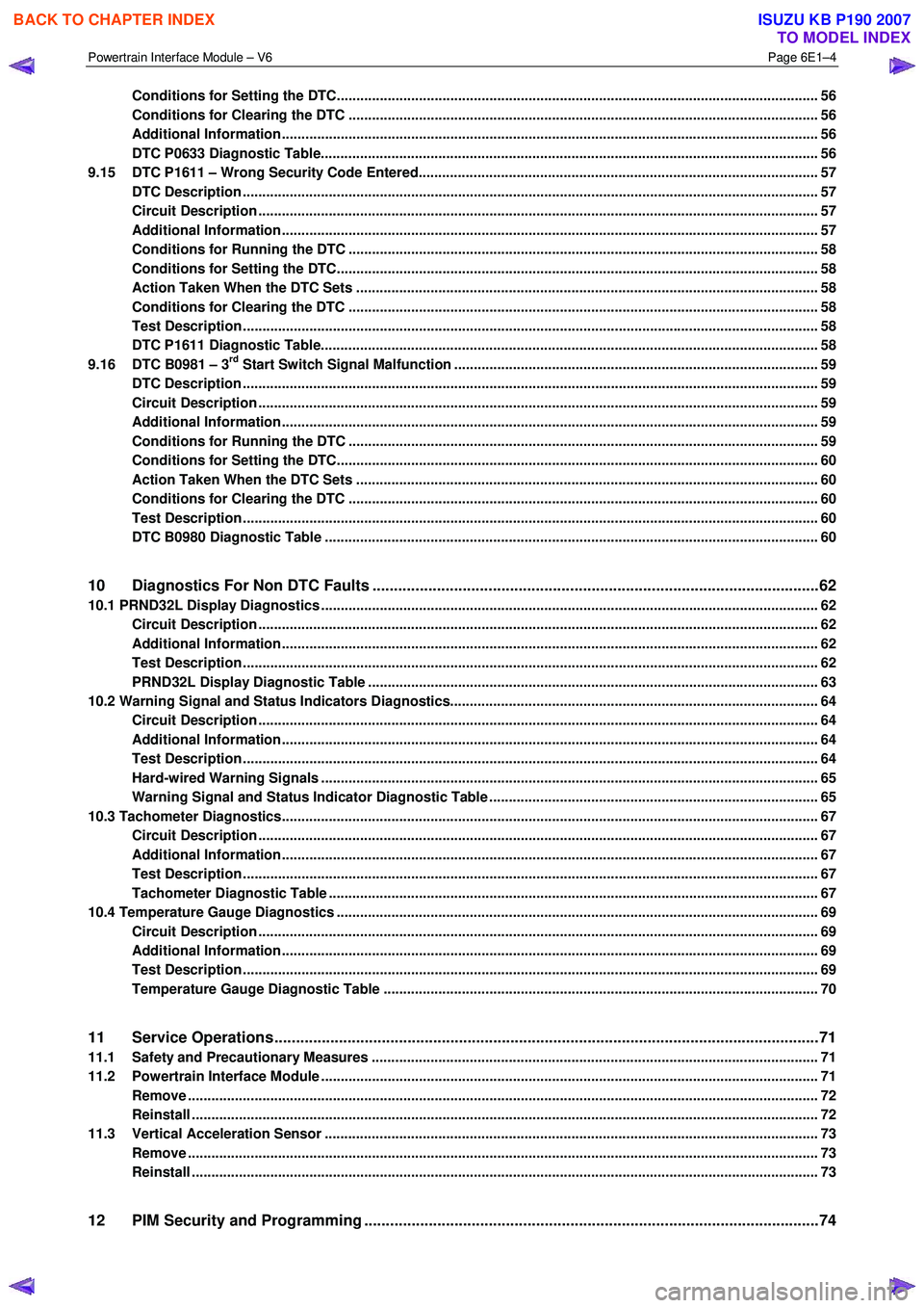
Conditions for Setting the DTC........................................................................................................................... 56
Conditions for Clearing the DTC ................................................................................................ ........................ 56
Additional Information......................................................................................................................................... 56
DTC P0633 Diagnostic Table..................................................................................................... .......................... 56
9.15 DTC P1611 – Wrong Security Code Entered........................................................................................ .............. 57
DTC Description ................................................................................................................................................... 57
Circuit Description ............................................................................................................................................... 57
Additional Information......................................................................................................... ................................ 57
Conditions for Running the DTC ................................................................................................. ....................... 58
Conditions for Setting the DTC........................................................................................................................... 58
Action Taken When the DTC Sets ................................................................................................. ..................... 58
Conditions for Clearing the DTC ........................................................................................................................ 58
Test Description ................................................................................................................................................... 58
DTC P1611 Diagnostic Table..................................................................................................... .......................... 58
9.16 DTC B0981 – 3rd Start Switch Signal Malfunction ............................................................................................. 59
DTC Description ................................................................................................................................................... 59
Circuit Description ............................................................................................................................................... 59
Additional Information......................................................................................................... ................................ 59
Conditions for Running the DTC ................................................................................................. ....................... 59
Conditions for Setting the DTC........................................................................................................................... 60
Action Taken When the DTC Sets ................................................................................................. ..................... 60
Conditions for Clearing the DTC ........................................................................................................................ 60
Test Description ................................................................................................................................................... 60
DTC B0980 Diagnostic Table ..................................................................................................... ......................... 60
10 Diagnostics For Non DTC Faults ................................................................................................. .......62
10.1 PRND32L Display Diagnostics ............................................................................................... ................................ 62
Circuit Description ............................................................................................................................................... 62
Additional Information......................................................................................................... ................................ 62
Test Description ................................................................................................................................................... 62
PRND32L Display Diagnostic Table ............................................................................................... .................... 63
10.2 Warning Signal and Status Indicators Diagnostics.......................................................................... .................... 64
Circuit Description ............................................................................................................................................... 64
Additional Information......................................................................................................... ................................ 64
Test Description ................................................................................................................................................... 64
Hard-wired Warning Signals ..................................................................................................... .......................... 65
Warning Signal and Status Indicator Diagnostic Table ........................................................................... ......... 65
10.3 Tachometer Diagnostics......................................................................................................................................... 67
Circuit Description ............................................................................................................................................... 67
Additional Information......................................................................................................... ................................ 67
Test Description ................................................................................................................................................... 67
Tachometer Diagnostic Table .................................................................................................... ......................... 67
10.4 Temperature Gauge Diagnostics ............................................................................................. .............................. 69
Circuit Description ............................................................................................................................................... 69
Additional Information......................................................................................................... ................................ 69
Test Description ................................................................................................................................................... 69
Temperature Gauge Diagnostic Table ............................................................................................. .................. 70
11 Service Operations ...............................................................................................................................71
11.1 Safety and Precautionary Measures .................................................................................................................. 71
11.2 Powertrain Interface Module ............................................................................................................................... 71
Remove ................................................................................................................................................................. 72
Reinstall ................................................................................................................................................................ 72
11.3 Vertical Acceleration Sensor ................................................................................................... ........................... 73
Remove ................................................................................................................................................................. 73
Reinstall ................................................................................................................................................................ 73
12 PIM Security and Programming ................................................................................................... .......74
BACK TO CHAPTER INDEX
TO MODEL INDEX
ISUZU KB P190 2007
Page 3669 of 6020
Powertrain Interface Module – V6 Page 6E1–8
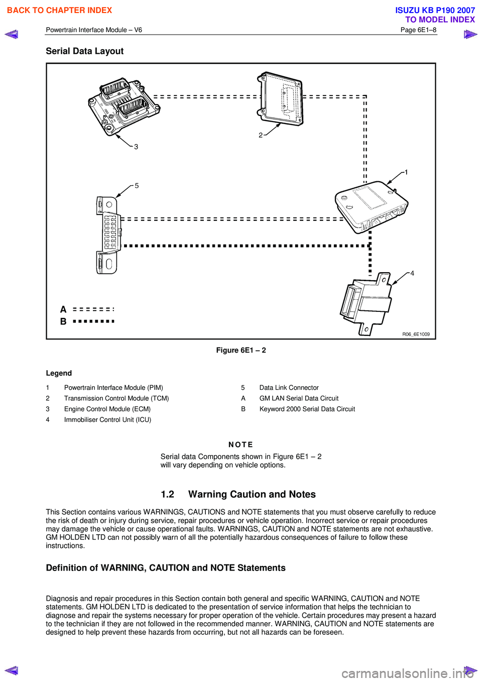
Serial Data Layout
Figure 6E1 – 2
Legend
1 Powertrain Interface Module (PIM)
2 Transmission Control Module (TCM)
3 Engine Control Module (ECM)
4 Immobiliser Control Unit (ICU)
5 Data Link Connector
A GM LAN Serial Data Circuit
B Keyword 2000 Serial Data Circuit
NOTE
Serial data Components shown in Figure 6E1 – 2
will vary depending on vehicle options.
1.2 Warning Caution and Notes
This Section contains various W ARNINGS, CAUTIONS and NOTE statements that you must observe carefully to reduce
the risk of death or injury during service, repair procedures or vehicle operation. Incorrect service or repair procedures
may damage the vehicle or cause operational faults. W ARNINGS, CAUTION and NOTE statements are not exhaustive.
GM HOLDEN LTD can not possibly warn of all the potentially hazardous consequences of failure to follow these
instructions.
Definition of WARNING, CAUTION and NOTE Statements
Diagnosis and repair procedures in this Section contain both general and specific W ARNING, CAUTION and NOTE
statements. GM HOLDEN LTD is dedicated to the presentation of service information that helps the technician to
diagnose and repair the systems necessary for proper operation of the vehicle. Certain procedures may present a hazard
to the technician if they are not followed in the recommended manner. W ARNING, CAUTION and NOTE statements are
designed to help prevent these hazards from occurring, but not all hazards can be foreseen.
BACK TO CHAPTER INDEX
TO MODEL INDEX
ISUZU KB P190 2007
Page 3673 of 6020
Powertrain Interface Module – V6 Page 6E1–12
3 Component Description and
Operation
3.1 Powertrain Interface Module
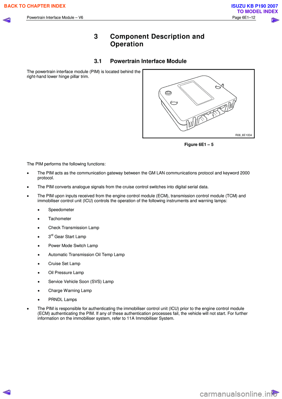
The powertrain interface module (PIM) is located behind the
right-hand lower hinge pillar trim.
Figure 6E1 – 5
The PIM performs the following functions:
• The PIM acts as the communication gateway between the GM LAN communications protocol and keyword 2000
protocol.
• The PIM converts analogue signals from the cruise control switches into digital serial data.
• The PIM upon inputs received from the engine control module (ECM), transmission control module (TCM) and
immobiliser control unit (ICU) controls the operation of the following instruments and warning lamps:
• Speedometer
• Tachometer
• Check Transmission Lamp
• 3
rd Gear Start Lamp
• Power Mode Switch Lamp
• Automatic Transmission Oil Temp Lamp
• Cruise Set Lamp
• Oil Pressure Lamp
• Service Vehicle Soon (SVS) Lamp
• Charge W arning Lamp
• PRNDL Lamps
• The PIM is responsible for authenticating the immobiliser control unit (ICU) prior to the engine control module
(ECM) authenticating the PIM. If any of these authentication processes fail, the vehicle will not start. For further
information on the immobiliser system, refer to 11A Immobiliser System.
BACK TO CHAPTER INDEX
TO MODEL INDEX
ISUZU KB P190 2007
Page 3677 of 6020
Powertrain Interface Module – V6 Page 6E1–16
Tech 2 PIM Diagnostic Tests
Tech 2 Limitations
Some DTCs trigger other DTCs to set, which causes Tech 2 to display multiple DTCs. In those situations, Tech 2 may
display more DTCs than is needed to rectify a fault.
W hen Tech 2 displays an output function, it displays only the command given by the PIM. If a connector is disconnected,
that fault will not register in the PIM output function. Tech 2 does not verify the command action.
The service technician must understand the system being diagnosed as well as the correct use and limitations of Tech 2
to be able to perform diagnostic procedures efficiently and successfully.
Tech 2 Intermittent Fault Tests
The following are lists of Tech 2 diagnostic tests that may be used to diagnose intermittent faults:
• W iggle test the suspected PIM wiring harness and connector while observing Tech 2 operating parameters of the
circuit being tested. If Tech 2 read-out fluctuates during this procedure, check the wiring harness circuit for loose
connection.
• Road test the vehicle in conditions that trigger the intermittent fault while an assistant observes the suspected Tech
2 operating parameter data.
• Capture and store data in the Snapshot mode when the fault occurs. The stored data may be replayed at a slower
rate to aid in diagnostics. Refer to Tech 2 User Instructions for more information on the Snapshot function.
• Operate suspected components to test their operation using Tech 2 Output Control Data.
BACK TO CHAPTER INDEX
TO MODEL INDEX
ISUZU KB P190 2007