2007 ISUZU KB P190 service
[x] Cancel search: servicePage 3763 of 6020
Automatic Transmission – 4L60E – General Information Page 7C1–3
1 Section Descriptions
Service information for the Hydra-matic 4L60E Automatic transmission has been divided into five Sections to assist the
technician to quickly locate the correct service, maintenance and diagnostic information.
The following provides a brief outline of each of the Sections.
• 7C1 Automatic Transmission – 4L60E – General Information
• 7C2 Automatic Transmission – 4L60E – Electrical Diagnosis
• 7C3 Automatic Transmission – 4L60E – Hydraulic and Mechanical Diagnosis
• 7C4 Automatic Transmission – 4L60E – On-vehicle Servicing
The following provides a brief outline of each of the Sections.
1.1 WARNINGS, CAUTIONS and NOTES
This Section contains various W ARNINGS, CAUTIONS and NOTE statements that you must observe carefully to reduce
the risk of death or injury during service, repair procedures or vehicle operation. Incorrect service or repair procedures
may damage the vehicle or cause operational faults. W ARNINGS, CAUTION and NOTE statements are not exhaustive.
GM HOLDEN LTD can not possibly warn of all the potentially hazardous consequences of failure to follow these
instructions.
Definition of WARNING, CAUTION and NOTE Statements
Diagnosis and repair procedures in this Section contain both general and specific W ARNING, CAUTION and NOTE
statements. GM HOLDEN LTD is dedicated to the presentation of service information that helps the technician to
diagnose and repair the systems necessary for proper operation of the vehicle. Certain procedures may present a hazard
to the technician if they are not followed in the recommended manner. W ARNING, CAUTION and NOTE statements are
designed to help prevent these hazards from occurring, but not all hazards can be foreseen.
WARNING Defined
A W ARNING statement immediately precedes an operating procedure or maintenance practice which, if not correctly
followed, could result in death or injury. A WARNING statement alerts you to take necessary action or not to take a
prohibited action. If a W ARNING statement is ignored, the following consequences may occur:
• Death or injury to the technician or other personnel working on the vehicle,
• Death or injury to other people in or near the workplace area, and / or
• Death or injury to the driver / or passenger(s) of the vehicle or other people, if the vehicle has been improperly
repaired.
CAUTION Defined
A CAUTION statement immediately precedes an operating procedure or maintenance practice which, if not correctly
followed, could result in damage to or destruction of equipment, or corruption of data. If a CAUTION statement is ignored,
the following consequences may occur:
• Damage to the vehicle,
• Unnecessary vehicle repairs or component replacement,
• Faulty operation or performance of any system or component being repaired,
• Damage to any system or components which depend on the proper operation of the system or component being
repaired,
• Faulty operation or performance of any systems or components which depend on the proper operation or
performance of the system or component under repair,
• Damage to fasteners, basic tools or special tools and / or
• Leakage of coolant, lubricant or other vital fluids.
NOTE Defined
A NOTE statement immediately precedes or follows an operating procedure, maintenance practice or condition that
requires highlighting. A NOTE statement also emphasises necessary characteristics of a diagnostic or repair procedure.
A NOTE statement is designed to:
• Clarify a procedure,
• Present additional information for accomplishing a procedure,
• Give insight into the reasons for performing a procedure in the recommended manner, and / or
• Present information that gives the technician the benefit of past experience in accomplishing a procedure with
greater ease.
BACK TO CHAPTER INDEX
TO MODEL INDEX
ISUZU KB P190 2007
Page 3764 of 6020
Automatic Transmission – 4L60E – General Information Page 7C1–4
1.2 7C1 Automatic Transmission – 4L60E –
General Information
This section provides general information about the automatic transmission, including:
• A glossary of terms,
• Transmission identification information,
• Electrical overview of the Transmission Control Module (TCM),
• Some notes that address safe workshop practices,
• Service notes relating to fasteners and consumable items used at various stages throughout this section,
• Special tools required to work on the transmission,
• Fastener torque specifications, and
• Transmission specifications.
For all information relating to the mechanical construction and function of the 4L60E automatic transmission, refer to the
General Motors Powertrain Group Electronically Controlled Automatic Transmission Technician’s Guide.
This guide includes such information as:
• Transmission Cutaway Views,
• Principles of Operation,
• Power Flow,
• Complete Hydraulic Circuits,
• Bushing and Bearing Locations,
• Seal Locations and
• Illustrated Parts List.
NOTE
Specifications quoted in this General Motors
Powertrain Group Electronically Controlled
Automatic Transmission Technician Guide may
not be for the vehicle you are working on. For
correct specifications refer to
7 Transmission Specifications.
Recommendations
When servicing the transmission, all parts should be cleaned and inspected. Individual units should be reassembled
before disassembly of other units to avoid confusion and interchanging of parts.
a Thoroughly clean the transmission exterior before removal of any component.
b Disassembly and reassembly must be made on a clean work bench. Cleanliness is of the utmost importance, the bench tools and parts must be kept clean at all times.
c Before installing screws and other fasteners into aluminium parts, dip screw threads into transmission fluid to prevent galling aluminium threads and to prevent screws from seizing.
d To prevent thread stripping, always use a torque wrench when installing screws or nuts.
e If threads in aluminium parts are stripped or damaged, the parts can be made serviceable by the use of commercially available thread inserts.
f Protective tools must be used when assembling seals to prevent damage. The slightest flaw in the sealing surface of the seal can cause an oil leak.
g Aluminium castings and valve parts are very susceptible to nicks, burrs, etc. and should be handled with care.
h Expand Internal snap rings and compress external snap rings if they are to be re-used to ensure proper seating when reinstalled.
i Do not re-use removed O-rings, gaskets and oil seals.
j Teflon oil seal rings should not be removed unless damaged.
k During assembly of each unit, all internal moving parts must be lubricated with transmission fluid.
Oil Cooler Pipes
Should any transmission fluid cooling pipe suffer accidental damage, a genuine replacement pipe must be fitted. Refer to
the current release of PartFinder™ to determine the correct part number for the particular engine and pipe involved.
Reworking of damaged pipes or hand made replacements are not permitted.
BACK TO CHAPTER INDEX
TO MODEL INDEX
ISUZU KB P190 2007
Page 3772 of 6020
Automatic Transmission – 4L60E – General Information Page 7C1–12
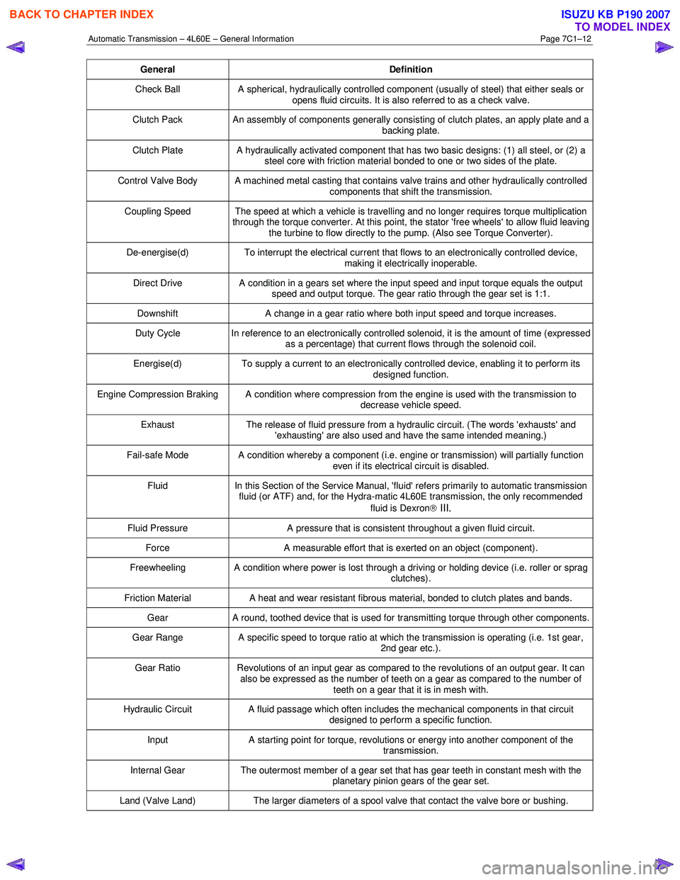
General Definition
Check Ball A spherical, hydraulically controlled component (usually of steel) that either seals or
opens fluid circuits. It is also referred to as a check valve.
Clutch Pack An assembly of components generally consisting of clutch plates, an apply plate and a
backing plate.
Clutch Plate A hydraulically activated component that has two basic designs: (1) all steel, or (2) a
steel core with friction material bonded to one or two sides of the plate.
Control Valve Body A machined metal casting that contains valve trains and other hydraulically controlled components that shift the transmission.
Coupling Speed The speed at which a vehicle is travelling and no longer requires torque multiplication through the torque converter. At this point, the stator 'free wheels' to allow fluid leaving
the turbine to flow directly to the pump. (Also see Torque Converter).
De-energise(d) To interrupt the electrical current that flows to an electronically controlled device,
making it electrically inoperable.
Direct Drive A condition in a gears set where the input speed and input torque equals the output
speed and output torque. The gear ratio through the gear set is 1:1.
Downshift A change in a gear ratio where both input speed and torque increases.
Duty Cycle In reference to an electronically controlled solenoid, it is the amount of time (expressed
as a percentage) that current flows through the solenoid coil.
Energise(d) To supply a current to an electronically controlled device, enabling it to perform its
designed function.
Engine Compression Braking A condition where compression from the engine is used with the transmission to decrease vehicle speed.
Exhaust The release of fluid pressure from a hydraulic circuit. (The words 'exhausts' and
'exhausting' are also used and have the same intended meaning.)
Fail-safe Mode A condition whereby a component (i.e. engine or transmission) will partially function even if its electrical circuit is disabled.
Fluid In this Section of the Service Manual, 'fluid' refers primarily to automatic transmission
fluid (or ATF) and, for the Hydra-matic 4L60E transmission, the only recommended
fluid is Dexron
III.
Fluid Pressure A pressure that is consistent throughout a given fluid circuit.
Force A measurable effort that is exerted on an object (component).
Freewheeling A condition where power is lost through a driving or holding device (i.e. roller or sprag
clutches).
Friction Material A heat and wear resistant fibrous material, bonded to clutch plates and bands.
Gear A round, toothed device that is used for transmitting torque through other components.
Gear Range A specific speed to torque ratio at which the transmission is operating (i.e. 1st gear,
2nd gear etc.).
Gear Ratio Revolutions of an input gear as compared to the revolutions of an output gear. It can
also be expressed as the number of teeth on a gear as compared to the number of
teeth on a gear that it is in mesh with.
Hydraulic Circuit A fluid passage which often includes the mechanical components in that circuit
designed to perform a specific function.
Input A starting point for torque, revolutions or energy into another component of the
transmission.
Internal Gear The outermost member of a gear set that has gear teeth in constant mesh with the
planetary pinion gears of the gear set.
Land (Valve Land) The larger diameters of a spool valve that contact the valve bore or bushing.
BACK TO CHAPTER INDEX
TO MODEL INDEX
ISUZU KB P190 2007
Page 3775 of 6020

Automatic Transmission – 4L60E – General Information Page 7C1–15
5 Service Notes
In the interests of safety to personnel, equipment and to the vehicle and its components, read and adhere to the following
notes whenever servicing operations are to be carried out on the Hydra-matic 4L60E automatic transmission. In addition,
some of this information also refers to sound workshop practices and, to achieve the design life of affected components.
Fasteners
• Always reinstall fasteners in the same locations as they were removed.
• If a fastener requires replacement, always use a part of the correct part number or of equal size and strength or
stronger.
General Workshop Practice
• Keep work area and tools clean.
• To avoid unnecessary contamination, always clean the exterior of the transmission before removing any parts.
• Do not use wiping cloths or rags because of the risk of lint being trapped in the transmission.
• Do not use solvents on:
• neoprene seals,
• composition faced clutch plates, or
• thrust washers.
• Always wear eye protection when using compressed air.
• Blow out all passages with compressed air. Only probe small passages with soft, thin wire.
• Handle parts with care to avoid nicks and scratches.
• Do not remove Teflon oil seal rings unless damaged or performing a complete overhaul.
• Expand internal snap rings and compress external snap rings to maximise retention and security.
• Lubricate all internal parts with transmission fluid (only use Dexron® III), as they are being installed.
• When installing cap screws into aluminium castings:
• always use a torque wrench and
• stripped or damaged threads in aluminium castings may be reconditioned by using commercially available
thread inserts.
• Once removed, replace all gaskets, seals and O-rings with new parts.
• Always use seal protectors where indicated and do not use gasket cement or sealant on any joined face unless
specified to do so.
BACK TO CHAPTER INDEX
TO MODEL INDEX
ISUZU KB P190 2007
Page 3777 of 6020
Automatic Transmission – 4L60E – General Information Page 7C1–17
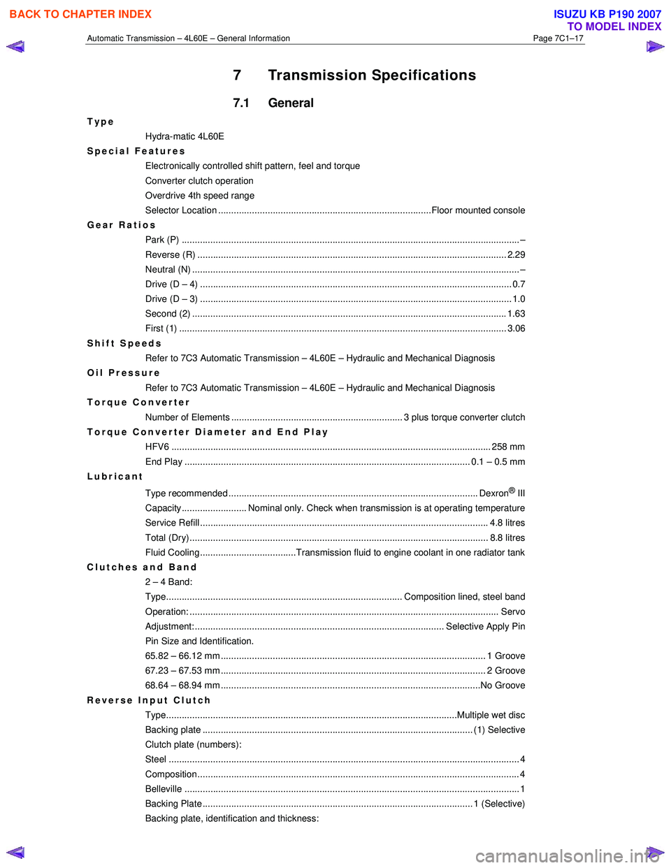
7 Transmission Specifications
7.1 General
Type
Hydra-matic 4L60E
Special Features
Electronically controlled shift pattern, feel and torque
Converter clutch operation
Overdrive 4th speed range
Selector Location ..................................................................................Floor mounted console
Gear Ratios Park (P) ....................................................................................................................... ........... –
Reverse (R) .................................................................................................................... ... 2.29
Neutral (N) .............................................................................................................................. –
Drive (D – 4) .................................................................................................................. ...... 0.7
Drive (D – 3) .................................................................................................................. ...... 1.0
Second (2) ......................................................................................................................... 1.63
First (1) ...................................................................................................................... ........ 3.06
Shift Speeds Refer to 7C3 Automatic Transmission – 4L60E – Hydraulic and Mechanical Diagnosis
Oil Pressure
Refer to 7C3 Automatic Transmission – 4L60E – Hydraulic and Mechanical Diagnosis
Torque Converter
Number of Elements .................................................................. 3 plus torque converter clutch
Torque Converter Diameter and End Play
HFV6 ........................................................................................................................... 258 mm
End Play .............................................................................................................. 0.1 – 0.5 mm
Lubricant
Type recommended ................................................................................................ Dexron
® III
Capacity......................... Nominal only. Check when transmission is at operating temperature
Service Refill ............................................................................................................... 4. 8 litres
Total (Dry)................................................................................................................... 8 .8 litres
Fluid Cooling.....................................Transmission fluid to engine coolant in one radiator tank
Clutches and Band 2 – 4 Band:
Type........................................................................................... Composition lined, steel band
Operation: ..................................................................................................................... .. Servo
Adjustment: ................................................................................................ Selective Apply Pin
Pin Size and Identification.
65.82 – 66.12 mm ...................................................................................................... 1 Groove
67.23 – 67.53 mm ...................................................................................................... 2 Groove
68.64 – 68.94 mm ....................................................................................................No Groove
Reverse Input Clutch Type................................................................................................................Multiple we t disc
Backing plate ........................................................................................................ (1) Select ive
Clutch plate (numbers):
Steel ....................................................................................................................................... 4
Composition............................................................................................................................ 4
Belleville ..................................................................................................................... ............ 1
Backing Plate ........................................................................................................ 1 (Selecti ve)
Backing plate, identification and thickness:
BACK TO CHAPTER INDEX
TO MODEL INDEX
ISUZU KB P190 2007
Page 3780 of 6020

Automatic Transmission – 4L60E – General Information Page 7C1–20
8 Special Tools
The following pages list and illustrate the special service tools required. The tools are classified into the following
categories:
Mandatory:
W hen required to perform routine maintenance operations and adjustments, or are required to carry out
fault diagnosis procedures.
Desirable:
These tools should be considered for purchase since their use will greatly facilitate performing designated
tasks and permit achievement of standard times.
Unique: These tools are those that must be employed when overhauling major assemblies or performing relatively
large tasks.
Available: Are those tools that are of a general nature for which commercially available equivalents exist, or tools
which have had previous application.
Unless otherwise specified, all tools are available from:
SPX Australia PTY. LTD. Service Solutions 28 Clayton Road
Notting Hill, Victoria, 3168
Telephone: (03) 9544 6222
Facsimile: (03) 9544 5222
Tool Number Illustration Description Tool Classification
700-4208
Pass-Thru Connector Remover
Used to release the four locking tangs
on the Pass-Thru connector from the
transmission case.
Previously released Desirable
J6125-1B
Slide Hammer
Used for a number of bush removal
operations.
Previously released Unique
J8092
Driver Handle
Used for a number of bush installation
operations.
Previously released Unique
J8433 Puller
Used with J21427-01 to remove the
output speed sensor ring from the
main shaft.
Previously released Unique
J8763-02 Holding Fixture
Used in conjunction with holding
fixture base J3289-20 to hold
automatic transmission.
Previously released. Unique
BACK TO CHAPTER INDEX
TO MODEL INDEX
ISUZU KB P190 2007
Page 3787 of 6020
Automatic Transmission – 4L60E – Electrical Diagnosis Page 7C2–1
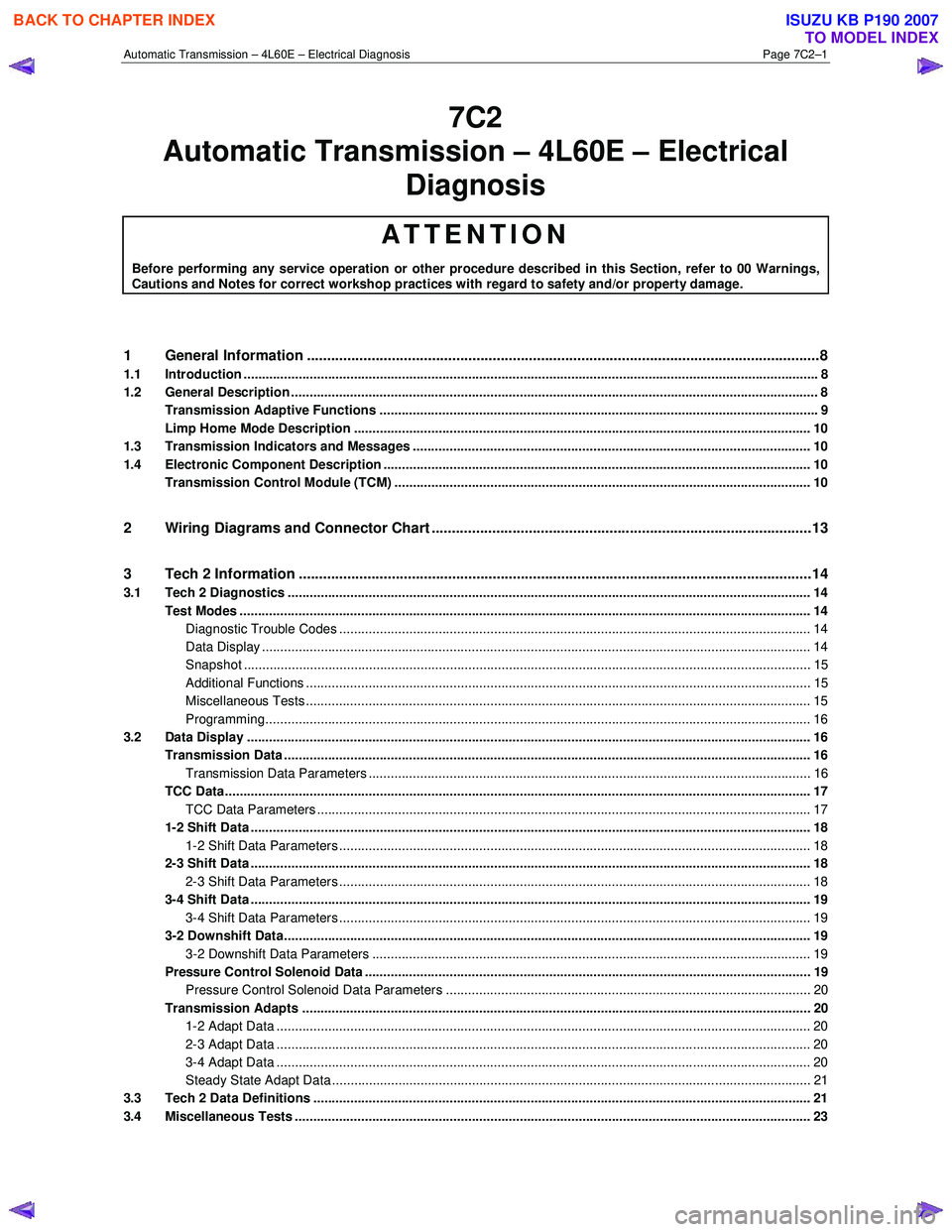
7C2
Diagnosis
ATTENTION
Before performing any service operation or other procedure described in this Section, refer to 00 Warnings, Cautions and Notes for correct workshop practices with regard to safety and/or property damage.
1 General Information ............................................................................................................ ...................8
1.1 Introduction ............................................................................................................................................................ 8
1.2 General Description ............................................................................................................................................... 8
Transmission Adaptive Functions ................................................................................................ ....................... 9
Limp Home Mode Description ............................................................................................................................ 10
1.3 Transmission Indicators and Messages ............................................................................................................ 10
1.4 Electronic Component Description ............................................................................................... ..................... 10
Transmission Control Module (TCM) ................................................................................................................. 10
2 Wiring Diagrams and Connector Chart ............................................................................................ ..13
3 Tech 2 Information ...............................................................................................................................14
3.1 Tech 2 Diagnostics .............................................................................................................................................. 14
Test Modes ........................................................................................................................................................... 14
Diagnostic Trouble Codes ....................................................................................................... ......................... 14
Data Display ..................................................................................................................................................... 14
Snapshot .......................................................................................................................................................... 15
Additional Functions ........................................................................................................... .............................. 15
Miscellaneous Tests ......................................................................................................................................... 15
Programming.................................................................................................................................................... 16
3.2 Data Display ......................................................................................................................................................... 16
Transmission Data .............................................................................................................. ................................. 16
Transmission Data Parameters ................................................................................................... ..................... 16
TCC Data............................................................................................................................................................... 17
TCC Data Parameters ............................................................................................................ .......................... 17
1-2 Shift Data ........................................................................................................................................................ 18
1-2 Shift Data Parameters ................................................................................................................................ 18
2-3 Shift Data ........................................................................................................................................................ 18
2-3 Shift Data Parameters ................................................................................................................................ 18
3-4 Shift Data ........................................................................................................................................................ 19
3-4 Shift Data Parameters ................................................................................................................................ 19
3-2 Downshift Data............................................................................................................................................... 19
3-2 Downshift Data Parameters ....................................................................................................................... 19
Pressure Control Solenoid Data ................................................................................................. ........................ 19
Pressure Control Solenoid Data Parameters ...................................................................................... ............. 20
Transmission Adapts .......................................................................................................................................... 20
1-2 Adapt Data ................................................................................................................................................. 20
2-3 Adapt Data ................................................................................................................................................. 20
3-4 Adapt Data ................................................................................................................................................. 20
Steady State Adapt Data ........................................................................................................ .......................... 21
3.3 Tech 2 Data Definitions ........................................................................................................ ............................... 21
3.4 Miscellaneous Tests ............................................................................................................................................ 23
Automatic Tra nsm ission – 4L60E – Electric al
BACK TO CHAPTER INDEX
TO MODEL INDEX
ISUZU KB P190 2007
Page 3813 of 6020
Automatic Transmission – 4L60E – Electrical Diagnosis Page 7C2–27
4 Diagnostics
4.1 Introduction
The transmission diagnostic procedure is organised in a logical structure that begins with the diagnostic system check
and as such must always be used as the starting point. The diagnostic system check directs the technician to the logical
steps necessary to diagnose a transmission driveability fault condition.
4.2 Basic Knowledge Required
A lack of basic understanding regarding
electronics, electrical wiring circuits and use
of electrical circuit testing tools when
performing any diagnostic procedure, could
result in incorrect diagnostic results or
damage to system components.
Understanding of the following is required to perform any of the diagnostic procedures detailed in this Service
Information:
• Basic electronics,
• Electrical wiring circuits,
• Electrical circuits testing, and
• Correct use of basic system diagnostic tools.
4.3 Diagnostic Precautions
When tests are required on connector
terminals, use the adapters in connector
adaptor kit J35616-C to prevent damage to
terminals.
The following precautions must be observed when performing all diagnostic procedures. Otherwise, incorrect diagnostic
results or damage to system components will occur:
1 Disconnection of the battery affects certain vehicle electronic systems.
2 Disconnect the battery negative lead when performing the following procedures:
• Disconnecting the electronic control module wiring harness connector/s or
• Charging the battery.
3 Disconnect the battery terminal ground lead and the electronic control module wiring harness connector before attempting any electric arc welding on the vehicle.
4 Do not start the engine if the battery terminal is not properly secured to the battery.
5 Do not disconnect or reconnect any of the following while the ignition is switched on or when the engine is running:
• Any electronic control module or system component electrical wiring connector, or
• Battery terminal leads.
6 Ensure that the correct procedure for disconnecting and connecting system electrical wiring harness connectors is always followed. For information on the correct procedure for disconnecting and connecting specific wiring
connectors, refer to 8A Electrical-Body and Chassis.
BACK TO CHAPTER INDEX
TO MODEL INDEX
ISUZU KB P190 2007