2007 ISUZU KB P190 service
[x] Cancel search: servicePage 3967 of 6020
TRANSMISSION CONTROL SYSTEM (AW30–40LE) 7A2-1
SECTION 7A2
TRANSMISSION CONTROL SYSTEM (AW30–40LE)
TABLE OF CONTENTS
Service Precaution ................................................. 7A2-2
General Description ............................................... 7A2-2
Components Location ........................................ 7A2-3
Operating Condition ........................................... 7A2-4
Electronic Control Diagram ...............................7A2-5
Transmission Control Module (TCM) (1/2) .....7A2-6
Transmission Control Module (TCM) (2/2) .....7A2-7
TCM Point Table ................................................. 7A2-8
TCM Voltage & Resistance Check Sheet .......7A2-9
Control System Diagram ...................................7A2-11
Control and Functions ........................................ 7A2-12
Functions of Input / Output Components ........7A2-15
CAN bus systems in automatic transmission
control (AW 30-40LE) ........................................ 7A2-16
High speed CAN bus .......................................... 7A2-16
Diagnosis ................................................................ 7A2-16
Electronic Diagnosis ........................................... 7A2-16
Check Trans Indicator ........................................ 7A2-16
On-Board Diagnostic (OBD) System Check ...7A2-17
“Check Trans” Check ......................................... 7A2-17
Tech 2 Operating ................................................ 7A2-20
Snapshot Display W ith TIS2000 ................... 7A2-26
Service Programming System (SPS) ............. 7A2-30
OBD Diagnostic Management System ............7A2-33
16 - Terminal Data Link Connector (DLC) ......7A2-34
Clear DTC ............................................................ 7A2-35
DTC Check .......................................................... 7A2-35
Self-diagnosis code (Flash code) display ........7A2-35
TCM Precaution .................................................. 7A2-36
Information On TCM .......................................... 7A2-36
TCM Diagnostic Trouble Codes .......................7A2-38
Diagnostic Trouble Code (DTC) Type
Definitions ........................................................... 7A2-39
DTC P0562 or P0563 (Flash Code 72 or 73) .....7A2-40
DTC P0602 (Flash Code 63) ............................. 7A2-43
DTC P0707 or P0708 (Flash Code 17) ............. 7A2-45
DTC P0712 (Flash Code 15) ............................. 7A2-49
DTC P0713 (Flash Code 16) ............................. 7A2-52
DTC P0717 (Flash Code 14) ............................. 7A2-55
DTC P0722 (Flash Code 11) ............................. 7A2-59
DTC P0741 (Flash Code 43) ............................. 7A2-63
DTC P0742 (Flash Code 53) ............................. 7A2-67
DTC P0746 (Flash Code 45) ............................. 7A2-71
DTC P0751 (Flash Code 41)..............................7A2-74
DTC P0752 (Flash Code 51)..............................7A2-78
DTC P0756 (Flash Code 42)..............................7A2-82
DTC P0757 (Flash Code 52)..............................7A2-86
DTC P0962 or P0963 (Flash Code 35) ..............7A2-90
DTC P0973 or P0974 (Flash Code 31) ..............7A2-93
DTC P0976 or P0977 (Flash Code 32) ..............7A2-97
DTC P1790 (Flash Code 61)..............................7A2-101
DTC P1791 (Flash Code 62)..............................7A2-103
DTC P2769 or P2770 (Flash Code 33) ..............7A2-105
DTC P2773 or 2774 (Flash Code 75) ................7A2-109
DTC U2104 (Flash Code 65) .............................7A2-112
DTC U2105 (Flash Code 67) .............................7A2-116
BACK TO CHAPTER INDEX
TO MODEL INDEX
ISUZU KB P190 2007
Page 3968 of 6020
7A2-2 TRANSMISSION CONTROL SYSTEM (AW30–40LE)
Service Precaution
WARNING: THIS VEHICLE HAS A SUPPLEMENTAL
RESTRAINT SYSTEM (SRS). REFER TO THE SRS
COMPONENT AND WIRING LOCATION VIEW IN
ORDER TO DETERMINE WHETHER YOU ARE
PERFORMING SERVICE ON OR NEAR THE SRS
COMPONENTS OR THE SRS WIRING. WHEN YOU
ARE PERFORMING SERVICE ON OR NEAR THE
SRS COMPONENTS OR THE SRS WIRING, REFER
TO THE SRS SERVICE INFORMATION. FAILURE TO
FOLLOW WARNINGS COULD RESULT IN
POSSIBLE AIR BAG DEPLOYMENT, PERSONAL
INJURY, OR OTHERWISE UNNEEDED SRS SYSTEM
REPAIRS.
CAUTION: Always use the correct fastener in the
proper location. When you replace a fastener, use
ONLY the exact part number for that application.
ISUZU will call out those fasteners that require a
replacement after removal. ISUZU will also call out
the fasteners that require thread lockers or thread
sealant. UNLESS OTHERWISE SPECIFIED, do not
use supplemental coatings (Paints, greases, o
r
other corrosion inhibitors) on threaded fasteners or
fastener joint interfaces. Generally, such coatings
adversely affect the fastener torque and the joint
clamping force, and may damage the fastener.
When you install fasteners, use the correct
tightening sequence and specifications. Following
these instructions can help you avoid damage to
parts and systems.
General Description
The AW 30-40LE is a 4–speed fully electronically
controlled automatic transmission. It uses a
microcomputer as a control unit to judge driving
conditions including throttle opening rate and vehicle
speed, then it sets the shifting point in the optimum
timing so that best driving performance can be
achieved.
In addition, the built–in driving mode select function can
select three driving modes according to the driver's
preference:
• Normal mode –Normal shift pattern.
• 3rd Start mode –Starts in 3rd gear to reduce slippage
on mud, ice or snow.
• Power mode –Delays upshift timing when more
powerful acceleration is required.
Also, the built–in fail–safe function (“emergency mode")
assures driving performance even if the vehicle speed
sensor, throttle signal or any solenoid fails.
Further, the self–diagnostic function conducts diagnosis
in a short time when the control system fails, thus
improving serviceability.
The major features of AW 30-40LE are as follows:
•
A compact structure consisting of 2 sets of planetary
gears and flat torque converter.
• Electronic control selects the optimum driving mode according to the driving conditions.
• Electronic control maintains the optimum hydraulic
pressure for clutch, band brake as well as
transmission so that shift feeling is improved.
• W ide gear ratio and high torque rate of torque
converter provide excellent starting performance.
• Optimum Lock-up control of each driving mode can
have it both ways driving performance and fuel
economy.
• Excellent shift quality can be achieved by the torque
management control through the CAN
communication with the engine.
BACK TO CHAPTER INDEX
TO MODEL INDEX
ISUZU KB P190 2007
Page 3996 of 6020
7A2-30 TRANSMISSION CONTROL SYSTEM (AW30–40LE)
Service Programming System (SPS)
The procedure to program the control unit by using the
Service Programming System (SPS) software
contained in TIS2000 is explained below.
NOTE: • Should Tech2 display “SPS Procedure was not
successful”, engine will not start, but no DTCs are
present, low battery voltage or poor electrical
connections should be the primary suspects.
Perform the SPS procedure again after rectifying
the fault/s.
IMPORTANT:
Perform the following checks before attempting to
program the control unit:
•
••
•
The Tech2 PCMCIA card is programmed with
the latest software release.
•
••
•
The latest release of TIS2000 is loaded on the
PC.
•
••
•
The vehicle battery is fully charged.
•
••
•
The control unit to be programmed is
connected to the vehicle.
1. Preparations of TIS 2000
1. Connect Tech 2 to P/C.
2. Check to see if Hardware Key is plugged into Port.
3. Activate TIS 2000 by P/C.
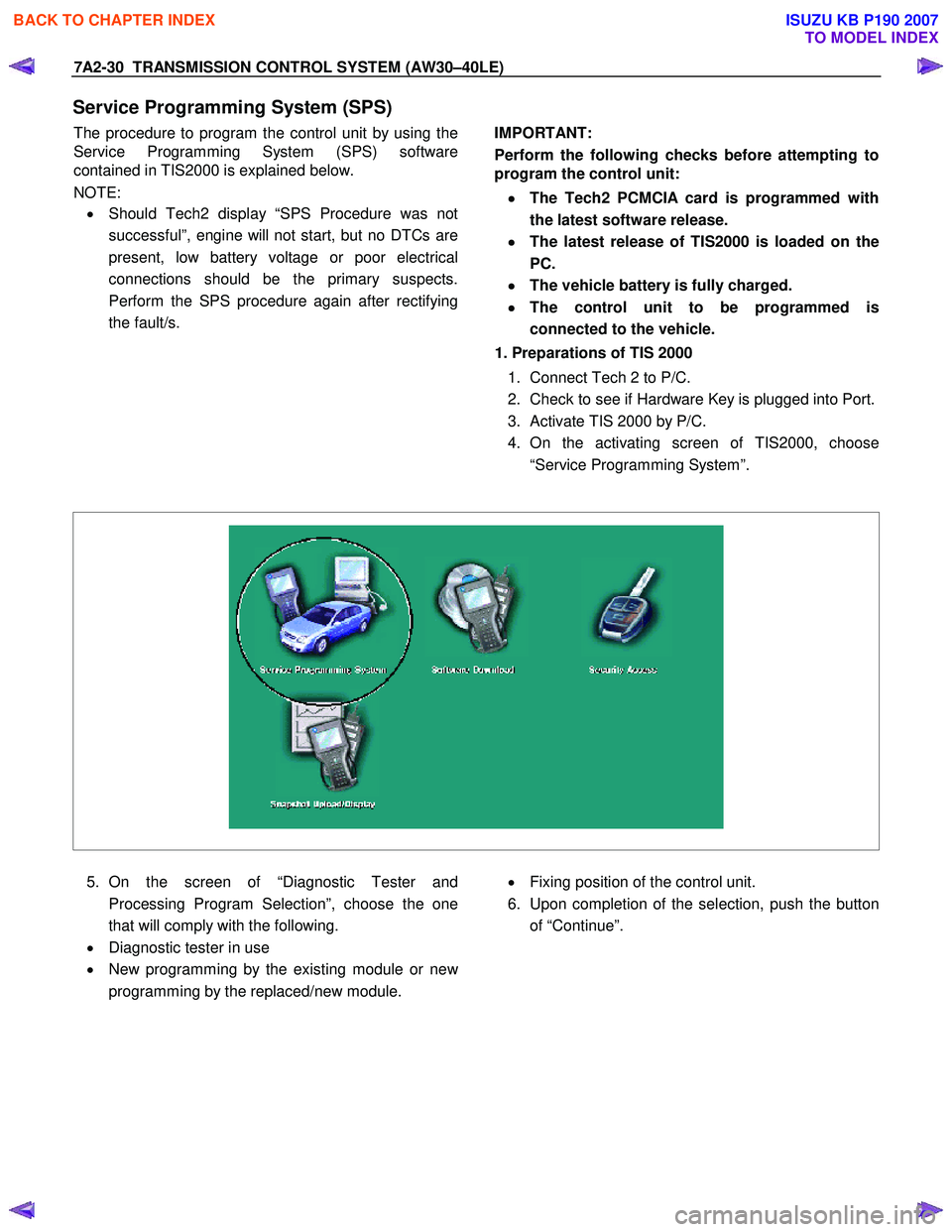
4. On the activating screen of TIS2000, choose
“Service Programming System”.
5. On the screen of “Diagnostic Tester and
Processing Program Selection”, choose the one
that will comply with the following.
• Diagnostic tester in use
• New programming by the existing module or ne
w
programming by the replaced/new module.
• Fixing position of the control unit.
6. Upon completion of the selection, push the button
of “Continue”.
BACK TO CHAPTER INDEX
TO MODEL INDEX
ISUZU KB P190 2007
Page 3997 of 6020
TRANSMISSION CONTROL SYSTEM (AW30–40LE) 7A2-31
2.Demand of Data
1. Connect Tech 2 to the vehicle. W hen activated b
y
turning on the power of Tech 2, push the "Enter"
switch.
2. Turn on the ignition switch (without starting the
engine)
3. In the main menu of Diagnostic Tester, push "F1:
Service Programming System (SPS)".
4. Push “F0: Request Info” of Tech 2.
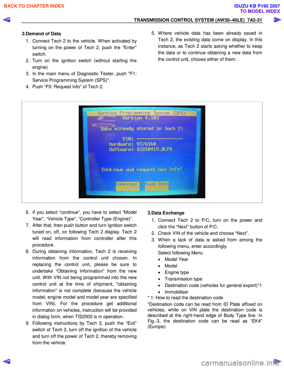
5. W here vehicle data has been already saved in
Tech 2, the existing data come on display. In this
instance, as Tech 2 starts asking whether to keep
the data or to continue obtaining a new data from
the control unit, choose either of them.
6. If you select “continue”, you have to select “Model
Year”, “Vehicle Type”, “Controller Type (Engine)”.
7.
After that. then push button and turn Ignition switch
tuned on, off, on following Tech 2 display. Tech 2
will read information from controller after this
procedure.
8. During obtaining information, Tech 2 is receiving
information from the control unit chosen. In
replacing the control unit, please be sure to
undertake “Obtaining Information” from the ne
w
unit. W ith VIN not being programmed into the new
control unit at the time of shipment, "obtaining
information" is not complete (because the vehicle
model, engine model and model year are specified
from VIN). For the procedure get additional
information on vehicles, instruction will be provided
in dialog form, when TIS2000 is in operation.
9. Following instructions by Tech 2, push the “Exit”
switch of Tech 2, turn off the ignition of the vehicle
and turn off the power of Tech 2, thereby removing
from the vehicle.
3.Data Exchange
1. Connect Tech 2 to P/C, turn on the power and
click the “Next” button of P/C.
2. Check VIN of the vehicle and choose “Next”.
3. W hen a lack of data is asked from among the
following menu, enter accordingly.
Select following Menu
• Model Year
• Model
• Engine type
• Transmission type
• Destination code (vehicles for general export)*1
• Immobiliser
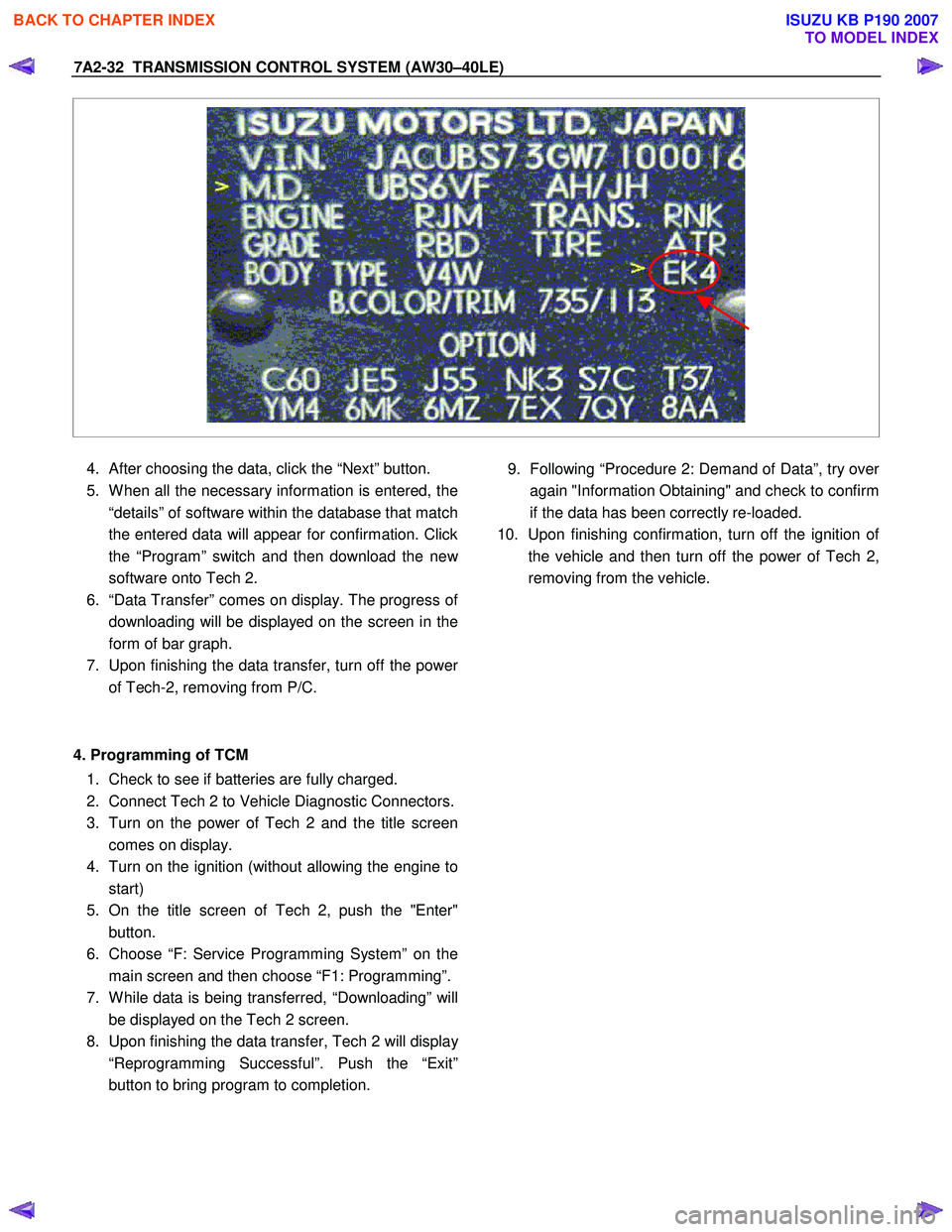
* 1: How to read the destination code
"Destination code can be read from ID Plate affixed on
vehicles, while on VIN plate the destination code is
described at the right-hand edge of Body Type line. In
Fig.-3, the destination code can be read as “EK4”
(Europe).
BACK TO CHAPTER INDEX
TO MODEL INDEX
ISUZU KB P190 2007
Page 3998 of 6020
7A2-32 TRANSMISSION CONTROL SYSTEM (AW30–40LE)
4. After choosing the data, click the “Next” button.
5. W hen all the necessary information is entered, the
“details” of software within the database that match
the entered data will appear for confirmation. Click
the “Program” switch and then download the ne
w
software onto Tech 2.
6. “Data Transfer” comes on display. The progress o
f
downloading will be displayed on the screen in the
form of bar graph.
7. Upon finishing the data transfer, turn off the powe
r
of Tech-2, removing from P/C.
4. Programming of TCM 1. Check to see if batteries are fully charged.
2. Connect Tech 2 to Vehicle Diagnostic Connectors.
3. Turn on the power of Tech 2 and the title screen
comes on display.
4. Turn on the ignition (without allowing the engine to
start)
5. On the title screen of Tech 2, push the "Enter"
button.
6. Choose “F: Service Programming System” on the
main screen and then choose “F1: Programming”.
7. W hile data is being transferred, “Downloading” will
be displayed on the Tech 2 screen.
8. Upon finishing the data transfer, Tech 2 will displa
y
“Reprogramming Successful”. Push the “Exit”
button to bring program to completion.
9. Following “Procedure 2: Demand of Data”, try ove
r
again "Information Obtaining" and check to confirm
if the data has been correctly re-loaded.
10. Upon finishing confirmation, turn off the ignition o
f
the vehicle and then turn off the power of Tech 2,
removing from the vehicle.
BACK TO CHAPTER INDEX
TO MODEL INDEX
ISUZU KB P190 2007
Page 4007 of 6020
TRANSMISSION CONTROL SYSTEM (AW30–40LE) 7A2-41
• All of the following conditions are met.
- Device Control is not operating
- Disable Normal Communication Service is receiving enable
- DTC Clear is not operating
Condition For Setting The DTC
W hen the TCM detects following conditions at 20 times
continuously.
• Ignition voltage is less than 9 volts for 1 second o
r
more continuously. (DTC P0562)
• Ignition voltage is more than 18 volts for 1 second o
r
more continuously. (DTC P0563)
Action Taken When The DTC Sets
• DTC stored.
Conditions For Clearing The DTC
• The DTC can be cleared from the TCM history by
using a scan tool.
• The DTC will be cleared from history when the
vehicle has achieved 40 warm-up cycles without a
failure reported.
•
After more than 1 second has elapsed after the
ignition key has been turned “ON”, short between
No.11 and No.4 (ground) of DLC (Data Link
Connector). Then, after 1 second, but within 6
seconds, discontinue shorting.
Diagnostic Aids
•
Inspect the wiring for poor electrical connection at the
TCM. Look for possible bent, backed out, deformed
or damaged terminals. Check for weak terminal
tension as well. Also check for a chafed wire that
could short to bare metal or other wiring.
Inspect for a broken wire inside the insulation.
• W hen diagnosing for a possible intermittent short o
r
open condition, move the wiring harness while
observing test equipment for a change.
Circuit/System Testing DTC P0562 or P0563
Step Action Value(s) YES NO
1
W as the On-Board Diagnostic (OBD) System Check
performed? — Go to
Step 2 Go to OBD
System Check
2 Using the 5-8840-0285-0 DMM, measure the battery voltage at the battery.
Is the battery voltage greater than the specified value? 11.5 V Go to
Step 3 Charge battery,
then go to Step 3
3 1. Install a scan tool.
2. Select “Ignition Volts” on a scan tool.
3. Start the engine and raise the engine speed to the specified value.
4. Load the electrical system by turning on the headlights, high blower, etc.
Is the ignition voltage approximately equal to the
specified value? More than
1000 rpm
9.0-18.0 V Go to
Step 4 Go to
Starting/
Charging
BACK TO CHAPTER INDEX
TO MODEL INDEX
ISUZU KB P190 2007
Page 4009 of 6020
TRANSMISSION CONTROL SYSTEM (AW30–40LE) 7A2-43
DTC P0602 (Flash Code 63)
Circuit Description
The Service Programming System (SPS) updates the
flash calibration files that are stored in a Transmission
Control Module (TCM). The calibration file
custom-tailors a module to a certain vehicle. The
calibration file contains data for things such as spark
curves and fuel control. W hen troubleshooting a
driveability problem, diagnosis may call fo
r
reprogramming the controller with newer calibration
information to correct a customer concern and Vehicle
Identification Number (VIN).
Condition for setting the DTC
W hen a VIN No. is not written into the TCM.
Action Taken When The DTC Sets
• DTC stored.
Conditions For Clearing The DTC
• The DTC can be cleared from the TCM history by
using a scan tool.
• The DTC will be cleared from history when the vehicle has achieved 40 warm-up cycles without a
failure reported.
•
After more than 1 second has elapsed after the
ignition key has been turned “ON”, short between
No.11 and No.4 (ground) of DLC (Data Link
Connector). Then, after 1 second, but within 6
seconds, discontinue shorting.
Diagnostic Aids
DTC P0602 is indicated when a VIN No. is not written
into the TCM.
A security lock is performed by SPS. And
not replace the TCM when DTC P0602 can repair b
y
SPS.
BACK TO CHAPTER INDEX
TO MODEL INDEX
ISUZU KB P190 2007
Page 4012 of 6020
7A2-46 TRANSMISSION CONTROL SYSTEM (AW30–40LE)
(2) Not emergency mode.
(3) All of the following conditions are met. • Device Control is not operating.
• Disable Normal Communication service is
receiving enable.
• DTC Clear is not operating.
Condition For Setting The DTC
DTC P0707
All of the following conditions are met for 30 seconds or
more continuously.
• All of the switches are “OFF”.
• Output revolution is more than 30 km/h (19 mph).
• Output revolution sensor is not detecting failure o
r
not deciding failure.
• The engine revolution is more than 1500 rpm.
DTC P0708
The following condition is met at 10 seconds
continuously.
• 2 switches or more are “ON” at the same time.
Action Taken When The DTC Sets
• No 3rd start mode.
• No slope control.
• No coast control.
• No output revolution sensor failure detection.
• No input revolution sensor failure detection.
• Keep oil temperature sensor OPEN failure detection accumulated timer.
• No T/F HI-Low SW failure detection.
• No shift solenoid functional failure detection.
• No L-up solenoid functional failure detection.
• No engine torque reduction at stall.
• Regard as D position. (DTC P0707)
• There is a priority in order of D, 3, 2, L, R, N, and P.
(DTC P0708)
• Check Trans “ON”.
• DTC stored.
• MIL request “ON”. (EURO 4 only)
Conditions For Clearing The DTC
•
The DTC can be cleared from the TCM history by
using a scan tool.
• The DTC will be cleared from history when the vehicle has achieved 40 warm-up cycles without a
failure reported.
•
After more than 1 second has elapsed after the
ignition key has been turned “ON”, short between
No.11 and No.4 (ground) of DLC (Data Link
Connector). Then, after 1 second, but within 6
seconds, discontinue shorting.
Diagnostic Aids
• Inspect the wiring for poor electrical connection at the
TCM. Look for possible bent, backed out, deformed
or damaged terminals. Check for weak terminal
tension as well. Also check for a chafed wire that
could short to bare metal or other wiring.
Inspect for a broken wire inside the insulation.
• W hen diagnosing for a possible intermittent short o
r
open condition, move the wiring harness while
observing test equipment for a change.
• Check neutral start switch for proper mounting and adjustment. (Refer to section 7A4 Components (1)
neutral start switch)
BACK TO CHAPTER INDEX
TO MODEL INDEX
ISUZU KB P190 2007