Page 4100 of 6020
ON-VEHICLE SERVICE (AW30–40LE) 7A3-15
“L" Position Test
1. W hile running above 80 km/h (50 mph) in the “D"
position, release your foot from the accelerato
r
pedal and shift into the “L" position.
Then check to see that the 2 →1 downshift occurs at
the specified point shown on the automatic shift
diagram.
RUW 37ASH000601
2. W hile running in the “L" position, check to see that
there is no upshift to 2nd gear.
3. W hile running in the “L" position, release the accelerator pedal and check the engine braking
effect.
4. Check for abnormal noise during acceleration and deceleration.
RUW 37ASH000701
“R" Position Test
Select into the “R" position and, while starting at full
throttle, check for slipping.
RUW 37ASH000801
“P" Position Test
Stop the vehicle on a grade (more than 9%) and afte
r
shifting into the “P" position, release the parking brake.
Then check to see that the parking lock pawl holds the
vehicle in place.
BACK TO CHAPTER INDEX
TO MODEL INDEX
ISUZU KB P190 2007
Page 4101 of 6020

7A3-16 ON-VEHICLE SERVICE (AW30–40LE)
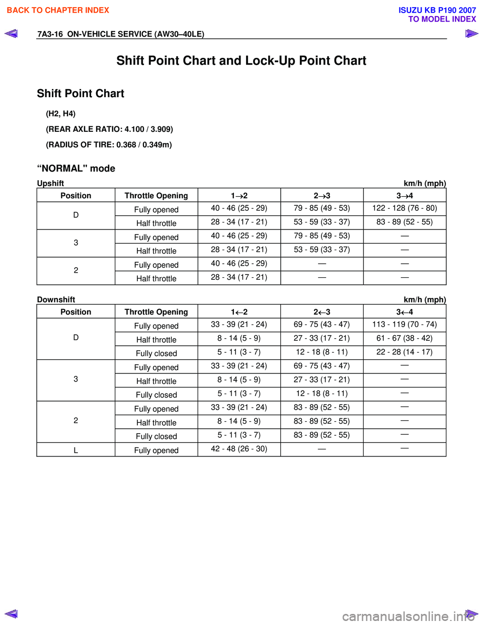
Shift Point Chart and Lock-Up Point Chart
Shift Point Chart
(H2, H4)
(REAR AXLE RATIO: 4.100 / 3.909)
(RADIUS OF TIRE: 0.368 / 0.349m)
“NORMAL" mode
Upshift km/h (mph)
Position Throttle Opening 1 →
→→
→
2 2 →
→→
→
3 3 →
→→
→
4
Fully opened 40 - 46 (25 - 29) 79 - 85 (49 - 53) 122 - 128 (76 - 80) D
Half throttle 28 - 34 (17 - 21) 53 - 59 (33 - 37) 83 - 89 (52 - 55)
Fully opened 40 - 46 (25 - 29) 79 - 85 (49 - 53) — 3
Half throttle 28 - 34 (17 - 21) 53 - 59 (33 - 37)
—
Fully opened 40 - 46 (25 - 29) — — 2
Half throttle 28 - 34 (17 - 21)
— —
Downshift km/h (mph)
Position Throttle Opening 1 ←
←←
←
2 2 ←
←←
←
3 3 ←
←←
←
4
Fully opened 33 - 39 (21 - 24) 69 - 75 (43 - 47) 113 - 119 (70 - 74)
Half throttle 8 - 14 (5 - 9) 27 - 33 (17 - 21) 61 - 67 (38 - 42) D
Fully closed 5 - 11 (3 - 7) 12 - 18 (8 - 11) 22 - 28 (14 - 17)
Fully opened 33 - 39 (21 - 24) 69 - 75 (43 - 47)
—
Half throttle 8 - 14 (5 - 9) 27 - 33 (17 - 21)
— 3
Fully closed 5 - 11 (3 - 7) 12 - 18 (8 - 11)
—
Fully opened 33 - 39 (21 - 24) 83 - 89 (52 - 55)
—
Half throttle 8 - 14 (5 - 9) 83 - 89 (52 - 55)
— 2
Fully closed 5 - 11 (3 - 7) 83 - 89 (52 - 55)
—
L Fully
opened 42 - 48 (26 - 30)
— —
BACK TO CHAPTER INDEX
TO MODEL INDEX
ISUZU KB P190 2007
Page 4102 of 6020

ON-VEHICLE SERVICE (AW30–40LE) 7A3-17
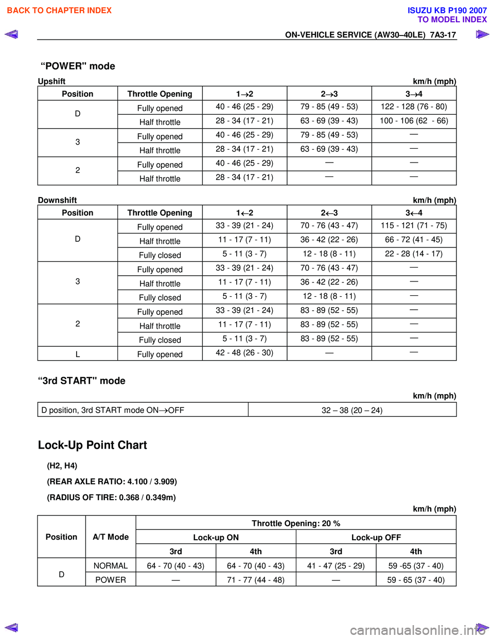
“POWER" mode
Upshift km/h (mph)
Position Throttle Opening 1 →
→→
→
2 2 →
→→
→
3 3 →
→→
→
4
Fully opened 40 - 46 (25 - 29) 79 - 85 (49 - 53) 122 - 128 (76 - 80) D
Half throttle 28 - 34 (17 - 21) 63 - 69 (39 - 43) 100 - 106 (62 - 66)
Fully opened 40 - 46 (25 - 29) 79 - 85 (49 - 53)
— 3
Half throttle 28 - 34 (17 - 21) 63 - 69 (39 - 43)
—
Fully opened 40 - 46 (25 - 29)
— — 2
Half throttle 28 - 34 (17 - 21)
— —
Downshift km/h (mph)
Position Throttle Opening 1 ←
←←
←
2 2 ←
←←
←
3 3 ←
←←
←
4
Fully opened 33 - 39 (21 - 24) 70 - 76 (43 - 47) 115 - 121 (71 - 75)
Half throttle 11 - 17 (7 - 11) 36 - 42 (22 - 26) 66 - 72 (41 - 45) D
Fully closed 5 - 11 (3 - 7) 12 - 18 (8 - 11) 22 - 28 (14 - 17)
Fully opened 33 - 39 (21 - 24) 70 - 76 (43 - 47)
—
Half throttle 11 - 17 (7 - 11) 36 - 42 (22 - 26)
— 3
Fully closed 5 - 11 (3 - 7) 12 - 18 (8 - 11)
—
Fully opened 33 - 39 (21 - 24) 83 - 89 (52 - 55)
—
Half throttle 11 - 17 (7 - 11) 83 - 89 (52 - 55)
— 2
Fully closed 5 - 11 (3 - 7) 83 - 89 (52 - 55)
—
L Fully
opened 42 - 48 (26 - 30)
— —
“3rd START" mode
km/h (mph)
D position, 3rd START mode ON
→OFF 32 – 38 (20 – 24)
Lock-Up Point Chart
(H2, H4)
(REAR AXLE RATIO: 4.100 / 3.909)
(RADIUS OF TIRE: 0.368 / 0.349m) km/h (mph)
Throttle Opening: 20 %
Lock-up ON Lock-up OFF
Position
A/T Mode
3rd 4th 3rd 4th
NORMAL 64 - 70 (40 - 43) 64 - 70 (40 - 43) 41 - 47 (25 - 29) 59 -65 (37 - 40)
D POW ER — 71 - 77 (44 - 48) — 59 - 65 (37 - 40)
BACK TO CHAPTER INDEX
TO MODEL INDEX
ISUZU KB P190 2007
Page 4103 of 6020
7A3-18 ON-VEHICLE SERVICE (AW30–40LE)
Transmission Fluid Level and Condition
Inspection
Park vehicle on level ground and set parking brake.
W ith the engine idling, move the shift lever through all
positions from “P" to “L", then return to position “P".
Check to see if the level of fluid comes to “HOT" range
of about 75 °
°°
°
C (167 °
°°
°
F) on the dipstick gauge.
If the level of fluid is too low, replenish to bring it to
maximum level in “HOT" range.
Inspection of fluid condition. If the ATF is except
normality (refer to the following table) or smells burnt,
try to find these cause and replace it.
RUW 37ASH002501
Color or ATF Condiction
Clear red Normality
Blackish discoloration Defects of power train parts (clutches)
W hite turbidity Include water
Discoloration of red brown Deterioration of ATF
BACK TO CHAPTER INDEX
TO MODEL INDEX
ISUZU KB P190 2007
Page 4104 of 6020
ON-VEHICLE SERVICE (AW30–40LE) 7A3-19
ATF Replacement
Inspection
NOTE: Do not overfill.
1. Remove the drain plug from oil pan and drain the
fluid.
RUW 17ASH013401
2. Reinstall the drain plug securely.
Torque: 19 N ⋅
⋅⋅
⋅
m (1.9 kgf ⋅
⋅⋅
⋅
m/14 Ib ⋅
⋅⋅
⋅
ft)
3. W ith the engine OFF, add new fluid through the fille
r
tube.
Drain and refill 5.2 liter
Dry fill 8.7 liter
Fluid Exxon Mobil ATF-3309
4. Start the engine and shift the selector into all
position from “P" through “L", and then shift into “P".
5. W ith the engine idling, check the fluid level. Add fluid up to the “COLD" level on the dipstick.
6. The ATF level must be checked again for correct level with the “HOT" level.
NOTE: To prevent fluid leaks, the drain plug gasket
must be replaced each time this plug is removed.
BACK TO CHAPTER INDEX
TO MODEL INDEX
ISUZU KB P190 2007
Page 4105 of 6020

7A3-20 ON-VEHICLE SERVICE (AW30–40LE)
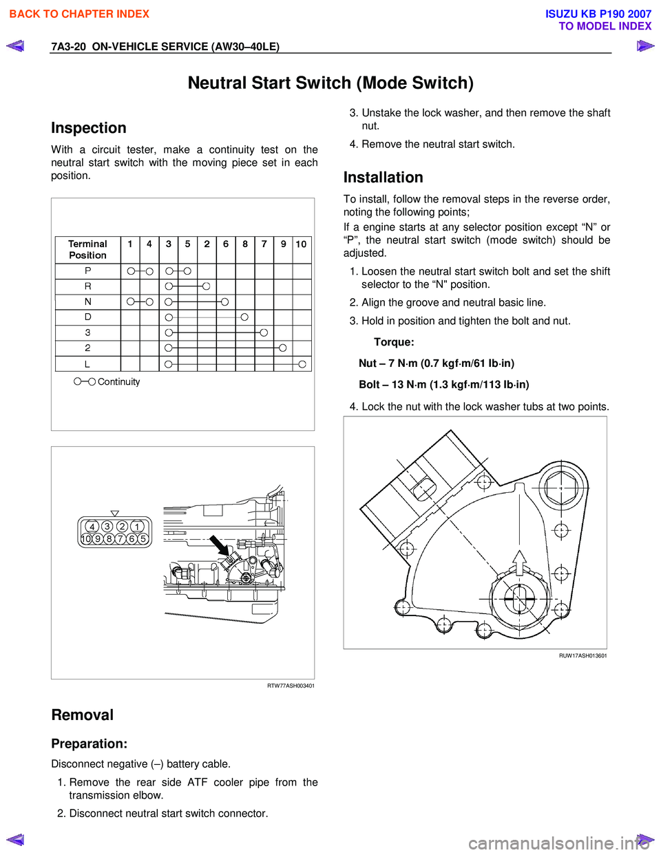
Neutral Start Switch (Mode Switch)
Inspection
W ith a circuit tester, make a continuity test on the
neutral start switch with the moving piece set in each
position.
RTW 77ASH003401
Removal
Preparation:
Disconnect negative (–) battery cable.
1. Remove the rear side ATF cooler pipe from the
transmission elbow.
2. Disconnect neutral start switch connector.
3. Unstake the lock washer, and then remove the shaft
nut.
4. Remove the neutral start switch.
Installation
To install, follow the removal steps in the reverse order,
noting the following points;
If a engine starts at any selector position except “N” o
r
“P”, the neutral start switch (mode switch) should be
adjusted.
1. Loosen the neutral start switch bolt and set the shift
selector to the “N" position.
2. Align the groove and neutral basic line.
3. Hold in position and tighten the bolt and nut.
Torque:
Nut – 7 N ⋅
⋅⋅
⋅
m (0.7 kgf ⋅
⋅⋅
⋅
m/61 Ib ⋅
⋅⋅
⋅
in)
Bolt – 13 N ⋅
⋅⋅
⋅
m (1.3 kgf ⋅
⋅⋅
⋅
m/113 Ib ⋅
⋅⋅
⋅
in)
4. Lock the nut with the lock washer tubs at two points.
RUW 17ASH013601
BACK TO CHAPTER INDEX
TO MODEL INDEX
ISUZU KB P190 2007
Page 4106 of 6020
ON-VEHICLE SERVICE (AW30–40LE) 7A3-21
Brake Signal
Inspection
Check that the brake light comes on when the brake
pedal is depressed.
310RW 020
BACK TO CHAPTER INDEX
TO MODEL INDEX
ISUZU KB P190 2007
Page 4107 of 6020

7A3-22 ON-VEHICLE SERVICE (AW30–40LE)
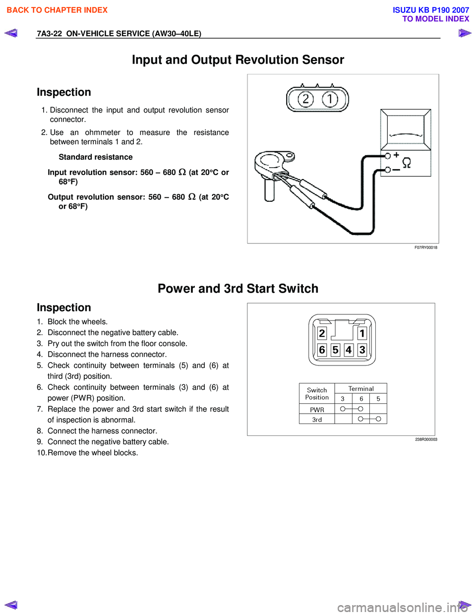
Input and Output Revolution Sensor
Inspection
1. Disconnect the input and output revolution sensor
connector.
2. Use an ohmmeter to measure the resistance between terminals 1 and 2.
Standard resistance
Input revolution sensor: 560 – 680
Ω
ΩΩ
Ω (at 20
°
°°
°
Cor
68 °
°°
°
F)
Output revolution sensor: 560 – 680
Ω
ΩΩ
Ω (at 20
°
°°
°
C
or 68 °
°°
°
F)
F07RY00018
Power and 3rd Start Switch
Inspection
1. Block the wheels.
2. Disconnect the negative battery cable.
3. Pry out the switch from the floor console.
4. Disconnect the harness connector.
5. Check continuity between terminals (5) and (6) at third (3rd) position.
6. Check continuity between terminals (3) and (6) at power (PW R) position.
7. Replace the power and 3rd start switch if the result of inspection is abnormal.
8. Connect the harness connector.
9. Connect the negative battery cable.
10. Remove the wheel blocks.
238R300003
BACK TO CHAPTER INDEX
TO MODEL INDEX
ISUZU KB P190 2007