2007 ISUZU KB P190 service
[x] Cancel search: servicePage 4132 of 6020
ON-VEHICLE SERVICE (AW30–40LE) 7A3-47
RTW 77ASH002201
RTW 77ASH002301
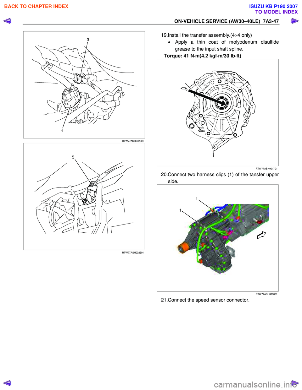
19.Install the transfer assembly.(4 ×4 only)
•
Apply a thin coat of molybdenum disulfide
grease to the input shaft spline.
Torque: 41 N ⋅
⋅⋅
⋅
m(4.2 kgf ⋅m/30 lb ⋅ft)
RTW 77ASH001701
20.Connect two harness clips (1) of the tansfer upper
side.
1
1
RTW 77ASH001601
21.Connect the speed sensor connector.
BACK TO CHAPTER INDEX
TO MODEL INDEX
ISUZU KB P190 2007
Page 4133 of 6020
7A3-48 ON-VEHICLE SERVICE (AW30–40LE)
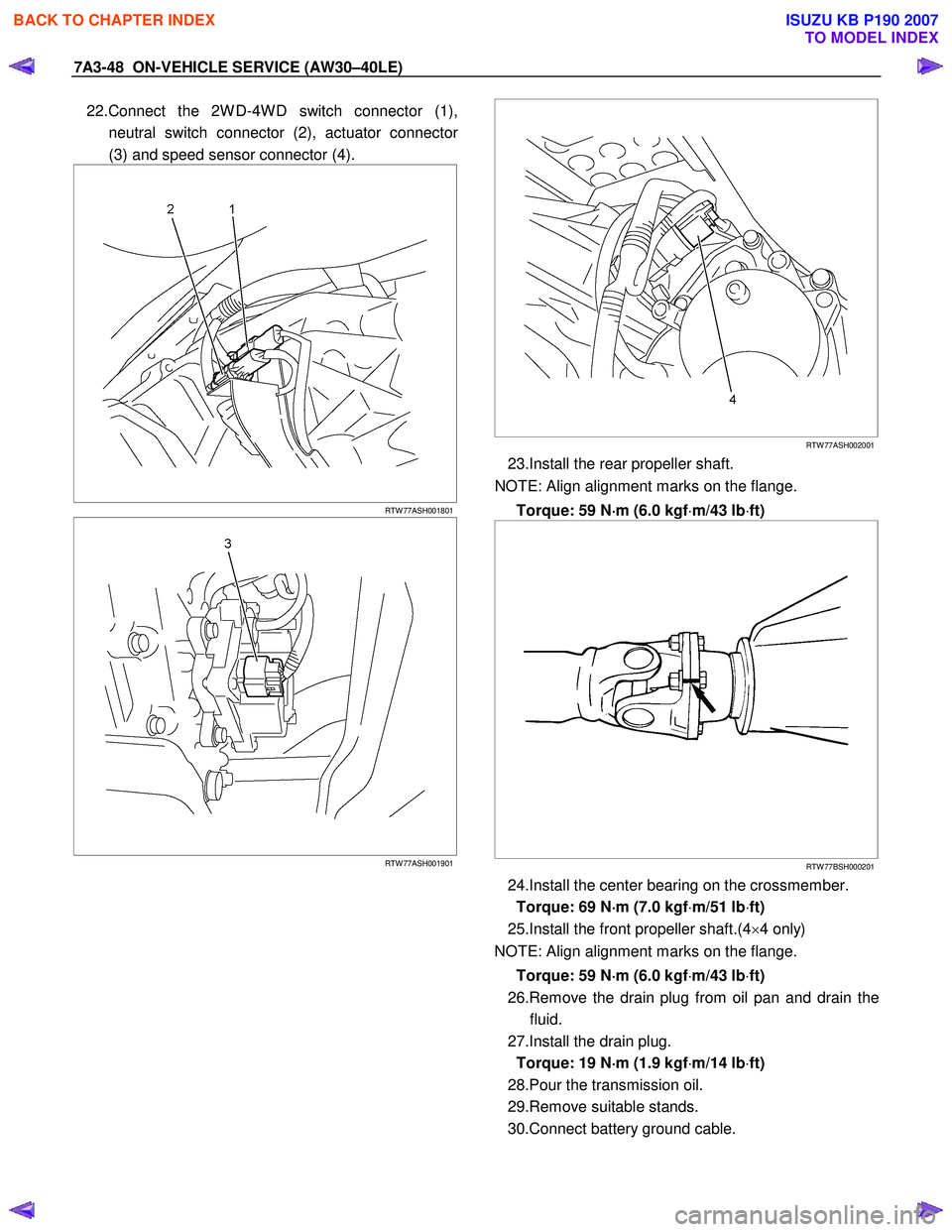
22.Connect the 2W D-4W D switch connector (1),
neutral switch connector (2), actuator connecto
r
(3) and speed sensor connector (4).
RTW 77ASH001801
RTW 77ASH001901
RTW 77ASH002001
23.Install the rear propeller shaft.
NOTE: Align alignment marks on the flange.
Torque: 59 N ⋅
⋅⋅
⋅
m (6.0 kgf ⋅m/43 lb ⋅ft)
RTW 77BSH000201
24.Install the center bearing on the crossmember.
Torque: 69 N ⋅
⋅⋅
⋅
m (7.0 kgf ⋅m/51 lb ⋅ft)
25.Install the front propeller shaft.(4 ×4 only)
NOTE: Align alignment marks on the flange.
Torque: 59 N ⋅
⋅⋅
⋅
m (6.0 kgf ⋅m/43 lb ⋅ft)
26.Remove the drain plug from oil pan and drain the fluid.
27.Install the drain plug. Torque: 19 N ⋅
⋅⋅
⋅
m (1.9 kgf ⋅m/14 lb ⋅ft)
28.Pour the transmission oil.
29.Remove suitable stands.
30.Connect battery ground cable.
BACK TO CHAPTER INDEX
TO MODEL INDEX
ISUZU KB P190 2007
Page 4134 of 6020
ON-VEHICLE SERVICE (AW30–40LE) 7A3-49
Major Components
Disassembly, inspection and reassembly of each
component group is indicated in the following chapter.
Before reassembly, make sure, again, that all
component groups are assembled correctly.
If something wrong is found in a certain component
group during assembly, inspect and repair this group
immediately.
General Assembly Notes:
1. The automatic transmission is composed of highly
precision-finished parts, necessitating careful
inspection before assembly because even a small
nick could cause fluid leakage or affect
performance.
2. Before assembling new clutch discs and brake
bands, soak them in automatic transmission fluid fo
r
at least thirty minutes.
3. Apply automatic transmission fluid on the sliding o
r
rotating surfaces of parts before assembly.
4. Use petroleum jelly to keep small parts in thei
r
palces.
5. Do not use adhesive cements on gaskets and similar parts.
6. W hen assembling the transmission, be sure to use new gaskets and O-rings.
7. Dry all parts with compressed air - never use shop rags.
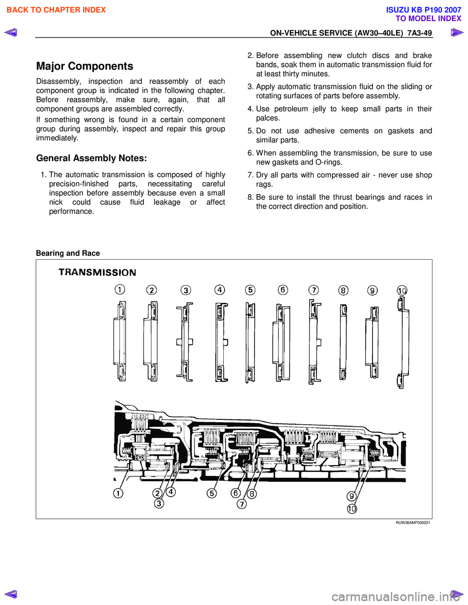
8. Be sure to install the thrust bearings and races in the correct direction and position.
Bearing and Race
RUW 36AMF000201
BACK TO CHAPTER INDEX
TO MODEL INDEX
ISUZU KB P190 2007
Page 4135 of 6020
7A3-50 ON-VEHICLE SERVICE (AW30–40LE)
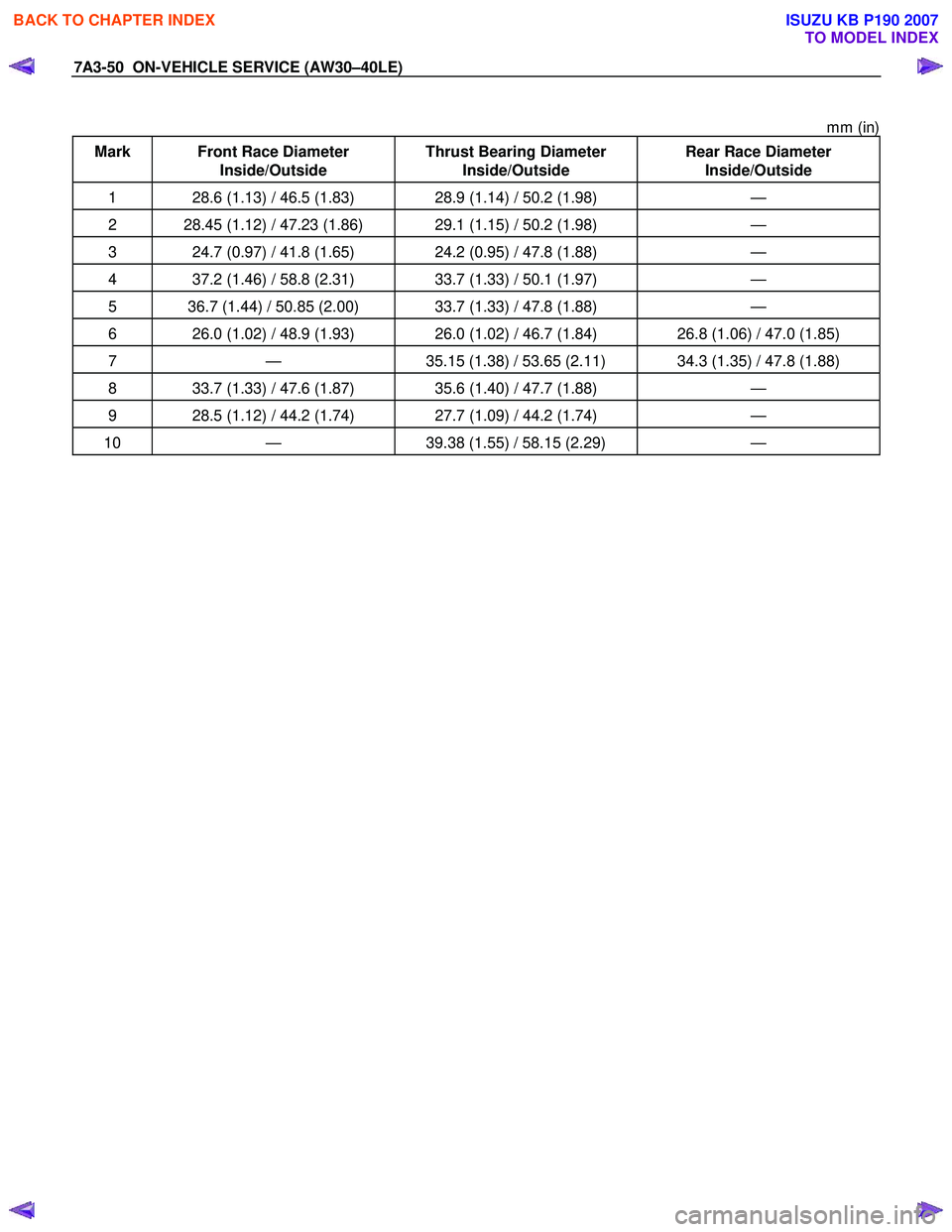
mm (in)
Mark Front Race Diameter Inside/Outside Thrust Bearing Diameter
Inside/Outside Rear Race Diameter
Inside/Outside
1 28.6 (1.13) / 46.5 (1.83) 28.9 (1.14) / 50.2 (1.98) —
2 28.45 (1.12) / 47.23 (1.86) 29.1 (1.15) / 50.2 (1.98) —
3 24.7 (0.97) / 41.8 (1.65) 24.2 (0.95) / 47.8 (1.88) —
4 37.2 (1.46) / 58.8 (2.31) 33.7 (1.33) / 50.1 (1.97) —
5 36.7 (1.44) / 50.85 (2.00) 33.7 (1.33) / 47.8 (1.88) —
6 26.0 (1.02) / 48.9 (1.93) 26.0 (1.02) / 46.7 (1.84) 26.8 (1.06) / 47.0 (1.85)
7 — 35.15 (1.38) / 53.65 (2.11) 34.3 (1.35) / 47.8 (1.88)
8 33.7 (1.33) / 47.6 (1.87) 35.6 (1.40) / 47.7 (1.88) —
9 28.5 (1.12) / 44.2 (1.74) 27.7 (1.09) / 44.2 (1.74) —
10 — 39.38 (1.55) / 58.15 (2.29) —
BACK TO CHAPTER INDEX
TO MODEL INDEX
ISUZU KB P190 2007
Page 4239 of 6020
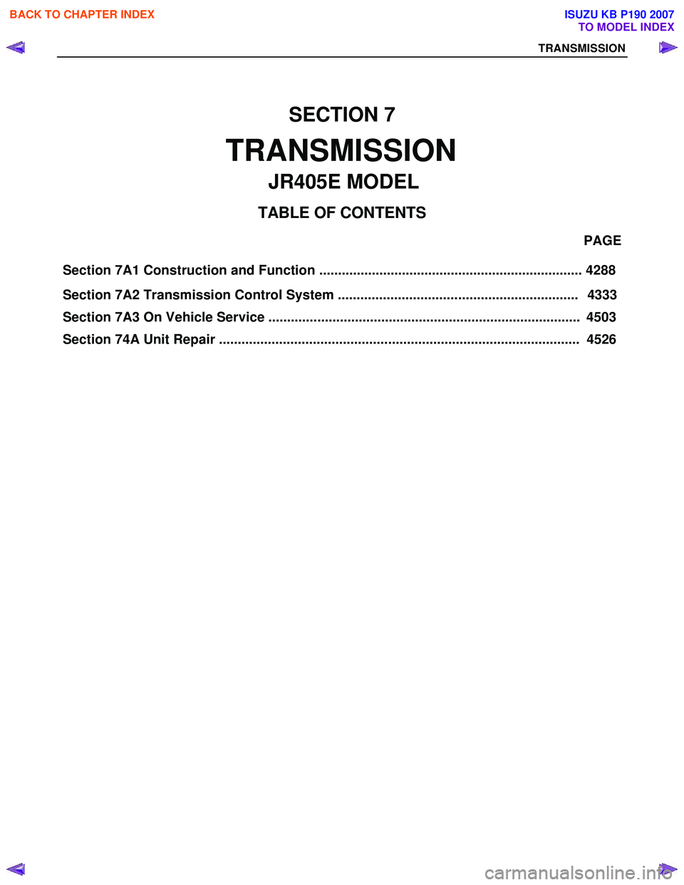
Section 7A1 Construction and Function ...................................................................... 4288 PAGE
Section 7A2 Transmission Control System ................................................................ 4333
Section 74A Unit Repair ................................................................................................ 4526
SECTION 7
TRANSMISSION
T A BLE OF CONTENTS
TRANSMISSION
JR405E MODEL
BACK TO CHAPTER INDEX
TO MODEL INDEX
Section 7A3 On Vehicle Service ................................................................................... 4503
ISUZU KB P190 2007
Page 4285 of 6020

TRANSMISSION CONTROL SYSTEM (JR405E) 7A2-1
TRANSMISSION
TRANSMISSION CONTROL SYSTEM (JR405E)
This manual conforms when Scan Tool of ISO CAN Base Software is used.
TABLE OF CONTENTS
Specifications ...................................................... 7A2-2Transmission General Specifications ............... 7A2-2
Transmission Fluid Temperature vs. Resistance..... 7A2-3
Clutch, Brake, Solenoid and Pressure Switch Logic........ 7A2-4
Diagnostic Trouble Code (DTC) List ................ 7A2-5
Schematic and Routing Diagrams....................... 7A2-6 Transmission Controls Schematics .................. 7A2-6
Component Locator........................................... 7A2-13 Transmission Controls Component Views ..... 7A2-13
Transmission Control Module (TCM) Connector End Views ................................... 7A2-17
Transmission Control Connector End Views.. 7A2-18
Diagnostic Information and Procedures ............ 7A2-21
Diagnostic Starting Point - Transmission Controls......... 7A2-21
Diagnostic System Check - Transmission Controls....... 7A2-22
Scan Tool Data List ........................................ 7A2-24
Scan Tool Data Definitions............................. 7A2-25
Scan Tool Output Controls ............................. 7A2-27
Scan Tool Does Not Power Up ...................... 7A2-28
Scan Tool Does Not Communicate with Keyword Device .................................... 7A2-29
Lost Communication with The Transmission Control Module (TCM)
.... 7A2-31
DTC P0560 (Flash Code 16).......................... 7A2-33
DTC P0602 .................................................... 7A2-35
DTC P0705 (Flash Code 17).......................... 7A2-36
DTC P0710 (Flash Code 15).......................... 7A2-40
DTC P0717 (Flash Code 14).......................... 7A2-44
DTC P0722 (Flash Code 11).......................... 7A2-47
DTC P0727 (Flash Code 13).......................... 7A2-50
DTC P0731, P0732, P0733 or P0734 (Flash Code 41, 42, 43 or 44)....................... 7A2-52
DTC P0748 (Flash Code 35).......................... 7A2-55
DTC P0753 (Flash Code 31).......................... 7A2-58
DTC P0758 (Flash Code 32).......................... 7A2-61
DTC P0763 (Flash Code 33).......................... 7A2-64
DTC P0768 (Flash Code 34).......................... 7A2-67
DTC P1120 (Flash Code 22).......................... 7A2-70
DTC P1750 (Flash Code 51).......................... 7A2-71
DTC P1755 (Flash Code 52).......................... 7A2-73
DTC P1853 (Flash Code 26).......................... 7A2-75
DTC P1858 (Flash Code 27).......................... 7A2-78
DTC P1860 (Flash Code 36).......................... 7A2-81
DTC P1863 (Flash Code 28).......................... 7A2-84
DTC P1875 (Flash Code 25).......................... 7A2-87
Check Trans Lamp Inoperative, Always On or Always Blinking ...................... 7A2-89
Symptoms - Transmission Controls .................. 7A2-92 Symptoms - Transmission Controls ............... 7A2-92
Intermittent Conditions ................................... 7A2-93 Vehicle Does Not Run .................................... 7A2-95
Trouble at Starting.......................................... 7A2-95
Faulty Gearshift .............................................. 7A2-95
Faulty Shift Pattern......................................... 7A2-95
No or Error Gearshift ...................................... 7A2-95
Faulty Operation During Running................... 7A2-95
Faulty Operation in Stopping.......................... 7A2-95
Faulty Lock Up ............................................... 7A2-95
No Lock Up .................................................... 7A2-95
Transmission Fluid Leak ................................ 7A2-95
Others ............................................................ 7A2-95
Test Instructions .............................................. 7A2-121 Line Pressure Test ....................................... 7A2-121
Stall Test ...................................................... 7A2-123
Time Lag Test .............................................. 7A2-124
Road Test..................................................... 7A2-125
TCM Signal Test .......................................... 7A2-134
Repair Instructions .......................................... 7A2-139
Transmission Controls Module (TCM) Replacement.... 7A2-139
Service Programming System (SPS) Description........ 7A2-139
Service Programming System (SPS) (Remote Procedure)......................... 7A2-140
Service Programming System (SPS) (Pass-Thru Procedure)..................... 7A2-141
Description and Operation .............................. 7A2-143 Transmission Identification Information........ 7A2-143
Transmission General Description ............... 7A2-143
Transmission Component Description ......... 7A2-144
Transmission Control System Description ... 7A2-152
Transmission Power Flow Description ......... 7A2-161
Special Tools and Equipment ......................... 7A2-170 Special Tools and Equipment ...................... 7A2-170
BACK TO CHAPTER INDEX
TO MODEL INDEX
ISUZU KB P190 2007
Page 4306 of 6020
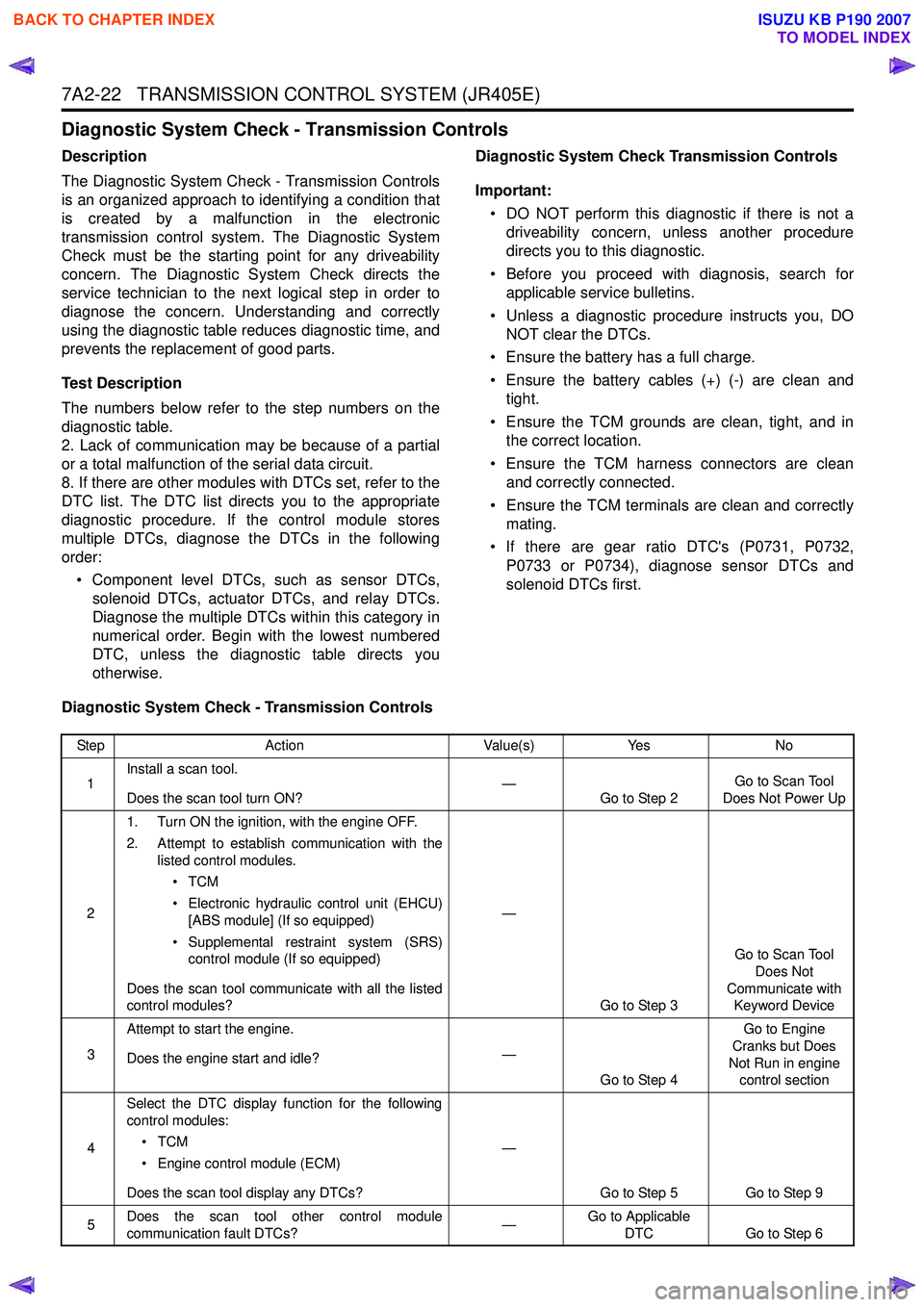
7A2-22 TRANSMISSION CONTROL SYSTEM (JR405E)
Diagnostic System Check - Transmission Controls
Description
The Diagnostic System Check - Transmission Controls
is an organized approach to identifying a condition that
is created by a malfunction in the electronic
transmission control system. The Diagnostic System
Check must be the starting point for any driveability
concern. The Diagnostic System Check directs the
service technician to the next logical step in order to
diagnose the concern. Understanding and correctly
using the diagnostic table reduces diagnostic time, and
prevents the replacement of good parts.
Test Description
The numbers below refer to the step numbers on the
diagnostic table.
2. Lack of communication may be because of a partial
or a total malfunction of the serial data circuit.
8. If there are other modules with DTCs set, refer to the
DTC list. The DTC list directs you to the appropriate
diagnostic procedure. If the control module stores
multiple DTCs, diagnose the DTCs in the following
order:
• Component level DTCs, such as sensor DTCs, solenoid DTCs, actuator DTCs, and relay DTCs.
Diagnose the multiple DTCs within this category in
numerical order. Begin with the lowest numbered
DTC, unless the diagnostic table directs you
otherwise. Diagnostic System Check Transmission Controls
Important: • DO NOT perform this diagnostic if there is not a driveability concern, unless another procedure
directs you to this diagnostic.
• Before you proceed with diagnosis, search for applicable service bulletins.
• Unless a diagnostic procedure instructs you, DO NOT clear the DTCs.
• Ensure the battery has a full charge.
• Ensure the battery cables (+) (-) are clean and tight.
• Ensure the TCM grounds are clean, tight, and in the correct location.
• Ensure the TCM harness connectors are clean and correctly connected.
• Ensure the TCM terminals are clean and correctly mating.
• If there are gear ratio DTC's (P0731, P0732, P0733 or P0734), diagnose sensor DTCs and
solenoid DTCs first.
Diagnostic System Check - Transmission Controls
Step Action Value(s)Yes No
1 Install a scan tool.
Does the scan tool turn ON? —
Go to Step 2 Go to Scan Tool
Does Not Power Up
2 1. Turn ON the ignition, with the engine OFF.
2. Attempt to establish communication with the listed control modules.
•TCM
• Electronic hydraulic control unit (EHCU) [ABS module] (If so equipped)
• Supplemental restraint system (SRS) control module (If so equipped)
Does the scan tool communicate with all the listed
control modules? —
Go to Step 3 Go to Scan Tool
Does Not
Communicate with Keyword Device
3 Attempt to start the engine.
Does the engine start and idle? —
Go to Step 4 Go to Engine
Cranks but Does
Not Run in engine control section
4 Select the DTC display function for the following
control modules:
•TCM
• Engine control module (ECM)
Does the scan tool display any DTCs? —
Go to Step 5 Go to Step 9
5 Does the scan tool other control module
communication fault DTCs? —Go to Applicable
DTC Go to Step 6
BACK TO CHAPTER INDEX
TO MODEL INDEX
ISUZU KB P190 2007
Page 4308 of 6020
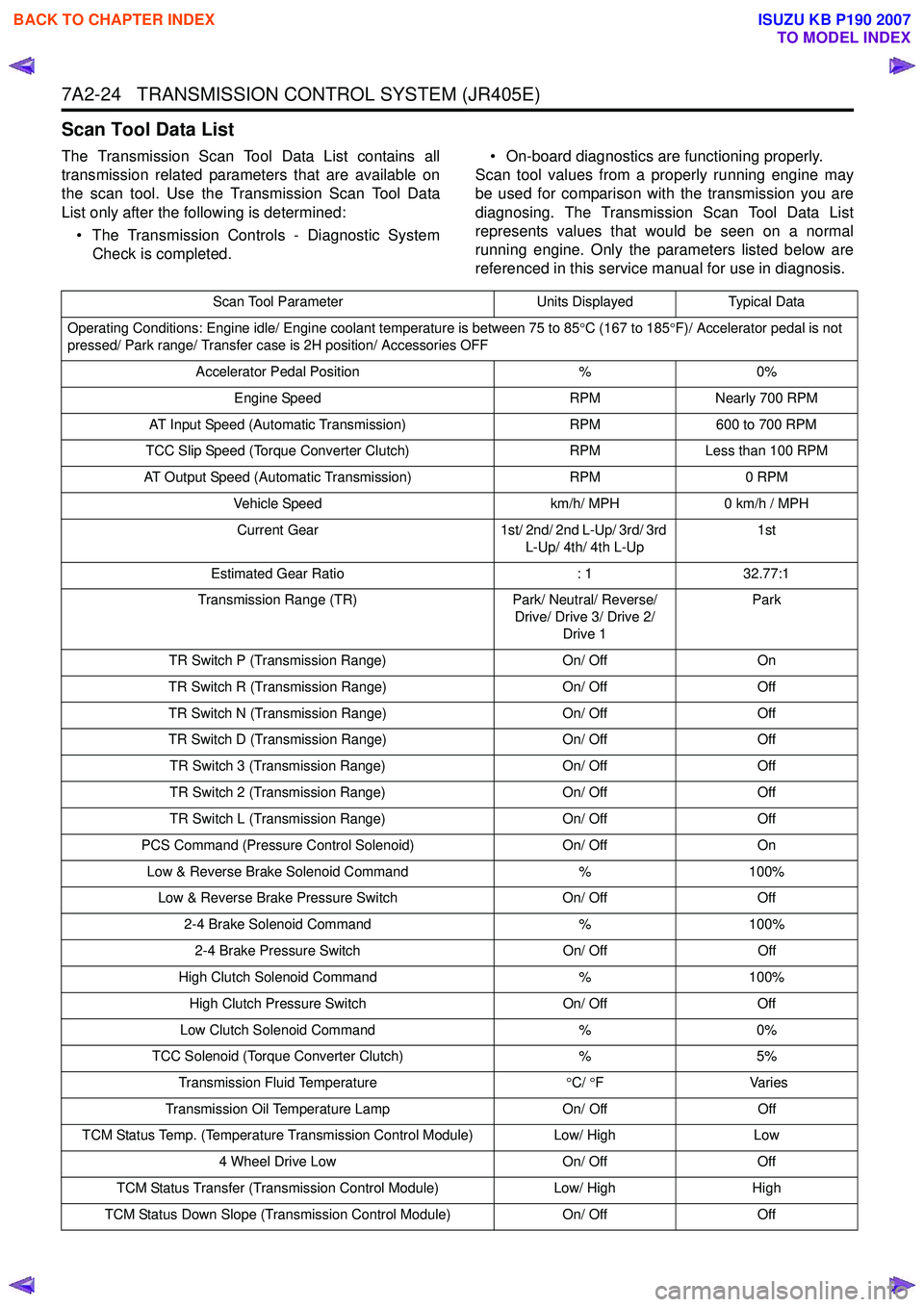
7A2-24 TRANSMISSION CONTROL SYSTEM (JR405E)
Scan Tool Data List
The Transmission Scan Tool Data List contains all
transmission related parameters that are available on
the scan tool. Use the Transmission Scan Tool Data
List only after the following is determined:
• The Transmission Controls - Diagnostic System Check is completed. • On-board diagnostics are functioning properly.
Scan tool values from a properly running engine may
be used for comparison with the transmission you are
diagnosing. The Transmission Scan Tool Data List
represents values that would be seen on a normal
running engine. Only the parameters listed below are
referenced in this service manual for use in diagnosis.
Scan Tool Parameter Units DisplayedTypical Data
Operating Conditions: Engine idle/ Engine coolant temperature is between 75 to 85 °C (167 to 185 °F)/ Accelerator pedal is not
pressed/ Park range/ Transfer case is 2H position/ Accessories OFF
Accelerator Pedal Position %0%
Engine Speed RPMNearly 700 RPM
AT Input Speed (Automatic Transmission) RPM600 to 700 RPM
TCC Slip Speed (Torque Converter Clutch) RPMLess than 100 RPM
AT Output Speed (Automatic Transmission) RPM0 RPM
Vehicle Speed km/h/ MPH0 km/h / MPH
Current Gear 1st/ 2nd/ 2nd L-Up/ 3rd/ 3rd
L-Up/ 4th/ 4th L-Up 1st
Estimated Gear Ratio : 132.77:1
Transmission Range (TR) Park/ Neutral/ Reverse/
Drive/ Drive 3/ Drive 2/ Drive 1 Park
TR Switch P (Transmission Range) On/ OffOn
TR Switch R (Transmission Range) On/ OffOff
TR Switch N (Transmission Range) On/ OffOff
TR Switch D (Transmission Range) On/ OffOff
TR Switch 3 (Transmission Range) On/ OffOff
TR Switch 2 (Transmission Range) On/ OffOff
TR Switch L (Transmission Range) On/ OffOff
PCS Command (Pressure Control Solenoid) On/ OffOn
Low & Reverse Brake Solenoid Command %100%
Low & Reverse Brake Pressure Switch On/ OffOff
2-4 Brake Solenoid Command %100%
2-4 Brake Pressure Switch On/ OffOff
High Clutch Solenoid Command %100%
High Clutch Pressure Switch On/ OffOff
Low Clutch Solenoid Command %0%
TCC Solenoid (Torque Converter Clutch) %5%
Transmission Fluid Temperature °C/ °F V arie s
Transmission Oil Temperature Lamp On/ OffOff
TCM Status Temp. (Temperature Transmission Control Module) Low/ HighLow
4 Wheel Drive Low On/ OffOff
TCM Status Transfer (Transmission Control Module) Low/ HighHigh
TCM Status Down Slope (Transmission Control Module) On/ OffOff
BACK TO CHAPTER INDEX
TO MODEL INDEX
ISUZU KB P190 2007