2007 ISUZU KB P190 service
[x] Cancel search: servicePage 4366 of 6020
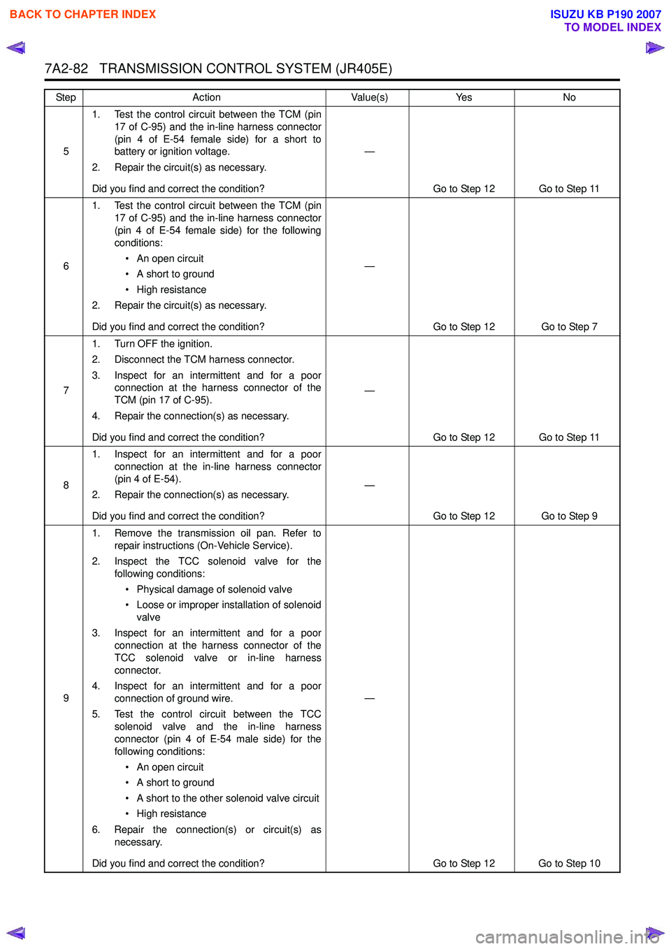
7A2-82 TRANSMISSION CONTROL SYSTEM (JR405E)
51. Test the control circuit between the TCM (pin
17 of C-95) and the in-line harness connector
(pin 4 of E-54 female side) for a short to
battery or ignition voltage.
2. Repair the circuit(s) as necessary.
Did you find and correct the condition? —
Go to Step 12 Go to Step 11
6 1. Test the control circuit between the TCM (pin
17 of C-95) and the in-line harness connector
(pin 4 of E-54 female side) for the following
conditions:
• An open circuit
• A short to ground
• High resistance
2. Repair the circuit(s) as necessary.
Did you find and correct the condition? —
Go to Step 12 Go to Step 7
7 1. Turn OFF the ignition.
2. Disconnect the TCM harness connector.
3. Inspect for an intermittent and for a poor connection at the harness connector of the
TCM (pin 17 of C-95).
4. Repair the connection(s) as necessary.
Did you find and correct the condition? —
Go to Step 12 Go to Step 11
8 1. Inspect for an intermittent and for a poor
connection at the in-line harness connector
(pin 4 of E-54).
2. Repair the connection(s) as necessary.
Did you find and correct the condition? —
Go to Step 12 Go to Step 9
9 1. Remove the transmission oil pan. Refer to
repair instructions (On-Vehicle Service).
2. Inspect the TCC solenoid valve for the following conditions:
• Physical damage of solenoid valve
• Loose or improper installation of solenoid valve
3. Inspect for an intermittent and for a poor connection at the harness connector of the
TCC solenoid valve or in-line harness
connector.
4. Inspect for an intermittent and for a poor connection of ground wire.
5. Test the control circuit between the TCC solenoid valve and the in-line harness
connector (pin 4 of E-54 male side) for the
following conditions:
• An open circuit
• A short to ground
• A short to the other solenoid valve circuit
• High resistance
6. Repair the connection(s) or circuit(s) as necessary.
Did you find and correct the condition? —
Go to Step 12 Go to Step 10
Step
Action Value(s)Yes No
BACK TO CHAPTER INDEX
TO MODEL INDEX
ISUZU KB P190 2007
Page 4367 of 6020
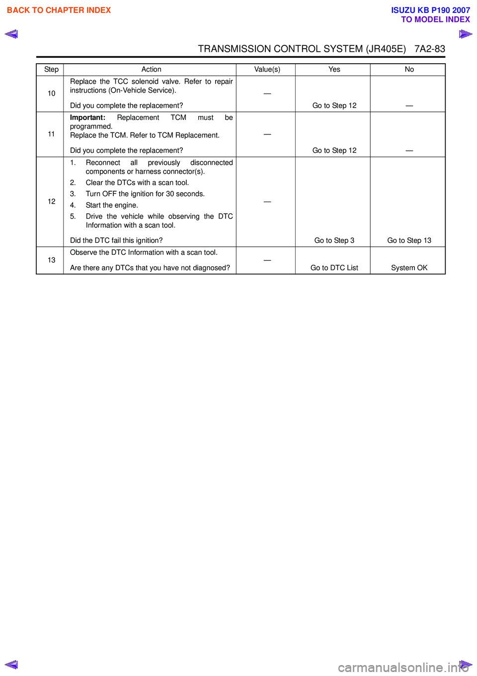
TRANSMISSION CONTROL SYSTEM (JR405E) 7A2-83
10Replace the TCC solenoid valve. Refer to repair
instructions (On-Vehicle Service).
Did you complete the replacement? —
Go to Step 12 —
11 Important:
Replacement TCM must be
programmed.
Replace the TCM. Refer to TCM Replacement.
Did you complete the replacement? —
Go to Step 12 —
12 1. Reconnect all previously disconnected
components or harness connector(s).
2. Clear the DTCs with a scan tool.
3. Turn OFF the ignition for 30 seconds.
4. Start the engine.
5. Drive the vehicle while observing the DTC Information with a scan tool.
Did the DTC fail this ignition? —
Go to Step 3 Go to Step 13
13 Observe the DTC Information with a scan tool.
Are there any DTCs that you have not diagnosed? —
Go to DTC List System OK
Step
Action Value(s)Yes No
BACK TO CHAPTER INDEX
TO MODEL INDEX
ISUZU KB P190 2007
Page 4370 of 6020
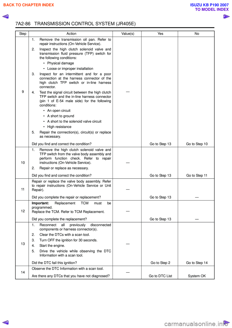
7A2-86 TRANSMISSION CONTROL SYSTEM (JR405E)
91. Remove the transmission oil pan. Refer to
repair instructions (On-Vehicle Service).
2. Inspect the high clutch solenoid valve and transmission fluid pressure (TFP) switch for
the following conditions:
• Physical damage
• Loose or improper installation
3. Inspect for an intermittent and for a poor connection at the harness connector of the
high clutch TFP switch or in-line harness
connector.
4. Test the signal circuit between the high clutch TFP switch and the in-line harness connector
(pin 1 of E-54 male side) for the following
conditions:
• An open circuit
• A short to ground
• A short to the solenoid valve circuit
• High resistance
5. Repair the connection(s), circuit(s) or replace as necessary.
Did you find and correct the condition? —
Go to Step 13 Go to Step 10
10 1. Remove the high clutch solenoid valve and
TFP switch from the valve body assembly and
perform function check. Refer to repair
instructions (On-Vehicle Service).
2. Repair or replace as necessary.
Did you find and correct the condition? —
Go to Step 13 Go to Step 11
11 Repair or replace the valve body assembly. Refer
to repair instructions (On-Vehicle Service or Unit
Repair).
Did you complete the repair or replacement? —
Go to Step 13 —
12 Important:
Replacement TCM must be
programmed.
Replace the TCM. Refer to TCM Replacement.
Did you complete the replacement? —
Go to Step 13 —
13 1. Reconnect all previously disconnected
components or harness connector(s).
2. Clear the DTCs with a scan tool.
3. Turn OFF the ignition for 30 seconds.
4. Start the engine.
5. Drive the vehicle while observing the DTC Information with a scan tool.
Did the DTC fail this ignition? —
Go to Step 2 Go to Step 14
14 Observe the DTC Information with a scan tool.
Are there any DTCs that you have not diagnosed? —
Go to DTC List System OK
Step
Action Value(s)Yes No
BACK TO CHAPTER INDEX
TO MODEL INDEX
ISUZU KB P190 2007
Page 4372 of 6020

7A2-88 TRANSMISSION CONTROL SYSTEM (JR405E)
61. Turn OFF the ignition.
2. Disconnect the TCM harness connector.
3. Inspect for an intermittent and for a poor connection at the harness connector of the
TCM (pin 22 of C-95).
4. Repair the connection(s) as necessary.
Did you find and correct the condition? —
Go to Step 9 Go to Step 8
7 1. Remove the transmission oil pan. Refer to
repair instructions (On-Vehicle Service).
2. Inspect for an intermittent and for a poor connection at the ground terminal or in-line
harness connector. Clean or tighten grounds
as necessary.
3. Repair the open circuit or high between the ground terminal and the in-line harness
connector (pin 11 of E-54 male side).
Did you complete the repair? —
Go to Step 9 —
8 Important:
Replacement TCM must be
programmed.
Replace the TCM. Refer to TCM Replacement.
Did you complete the replacement? —
Go to Step 9 —
9 1. Reconnect all previously disconnected
components or harness connector(s).
2. Clear the DTCs with a scan tool.
3. Turn OFF the ignition for 30 seconds.
4. Start the engine.
Did the DTC fail this ignition? —
Go to Step 3 Go to Step 10
10 Observe the DTC Information with a scan tool.
Are there any DTCs that you have not diagnosed? —
Go to DTC List System OK
Step
Action Value(s)Yes No
BACK TO CHAPTER INDEX
TO MODEL INDEX
ISUZU KB P190 2007
Page 4373 of 6020
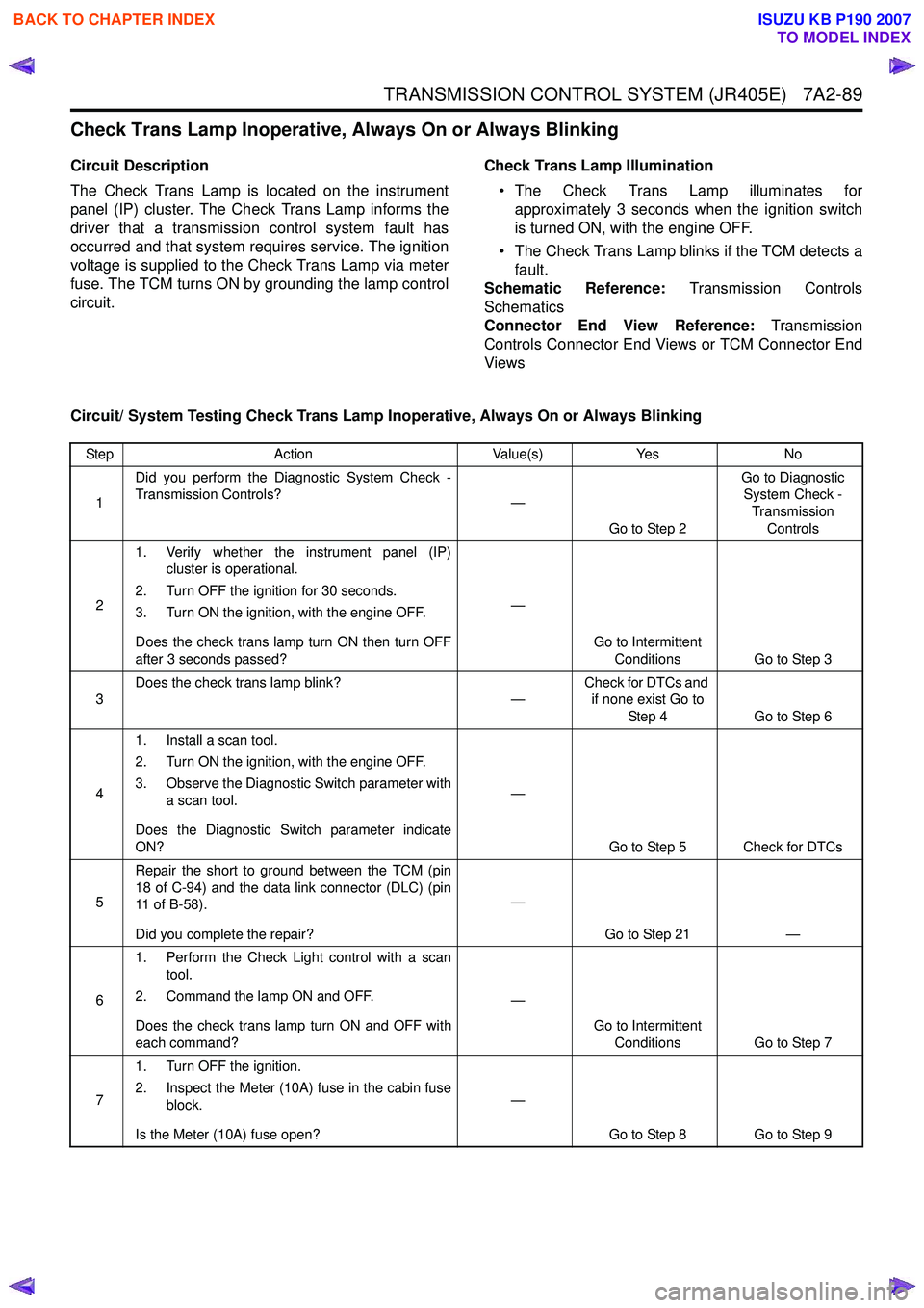
TRANSMISSION CONTROL SYSTEM (JR405E) 7A2-89
Check Trans Lamp Inoperative, Always On or Always Blinking
Circuit Description
The Check Trans Lamp is located on the instrument
panel (IP) cluster. The Check Trans Lamp informs the
driver that a transmission control system fault has
occurred and that system requires service. The ignition
voltage is supplied to the Check Trans Lamp via meter
fuse. The TCM turns ON by grounding the lamp control
circuit. Check Trans Lamp Illumination
• The Check Trans Lamp illuminates for approximately 3 seconds when the ignition switch
is turned ON, with the engine OFF.
• The Check Trans Lamp blinks if the TCM detects a fault.
Schematic Reference: Transmission Controls
Schematics
Connector End View Reference: Transmission
Controls Connector End Views or TCM Connector End
Views
Circuit/ System Testing Check Trans Lamp Inoperative, Always On or Always Blinking
Step Action Value(s)Yes No
1 Did you perform the Diagnostic System Check -
Transmission Controls? —
Go to Step 2 Go to Diagnostic
System Check -
Transmission Controls
2 1. Verify whether the instrument panel (IP)
cluster is operational.
2. Turn OFF the ignition for 30 seconds.
3. Turn ON the ignition, with the engine OFF.
Does the check trans lamp turn ON then turn OFF
after 3 seconds passed? —
Go to Intermittent Conditions Go to Step 3
3 Does the check trans lamp blink?
—Check for DTCs and
if none exist Go to
Step 4 Go to Step 6
4 1. Install a scan tool.
2. Turn ON the ignition, with the engine OFF.
3. Observe the Diagnostic Switch parameter with a scan tool.
Does the Diagnostic Switch parameter indicate
ON? —
Go to Step 5 Check for DTCs
5 Repair the short to ground between the TCM (pin
18 of C-94) and the data link connector (DLC) (pin
11 o f B - 5 8 ) .
Did you complete the repair? —
Go to Step 21 —
6 1. Perform the Check Light control with a scan
tool.
2. Command the lamp ON and OFF.
Does the check trans lamp turn ON and OFF with
each command? —
Go to Intermittent Conditions Go to Step 7
7 1. Turn OFF the ignition.
2. Inspect the Meter (10A) fuse in the cabin fuse block.
Is the Meter (10A) fuse open? —
Go to Step 8 Go to Step 9
BACK TO CHAPTER INDEX
TO MODEL INDEX
ISUZU KB P190 2007
Page 4386 of 6020
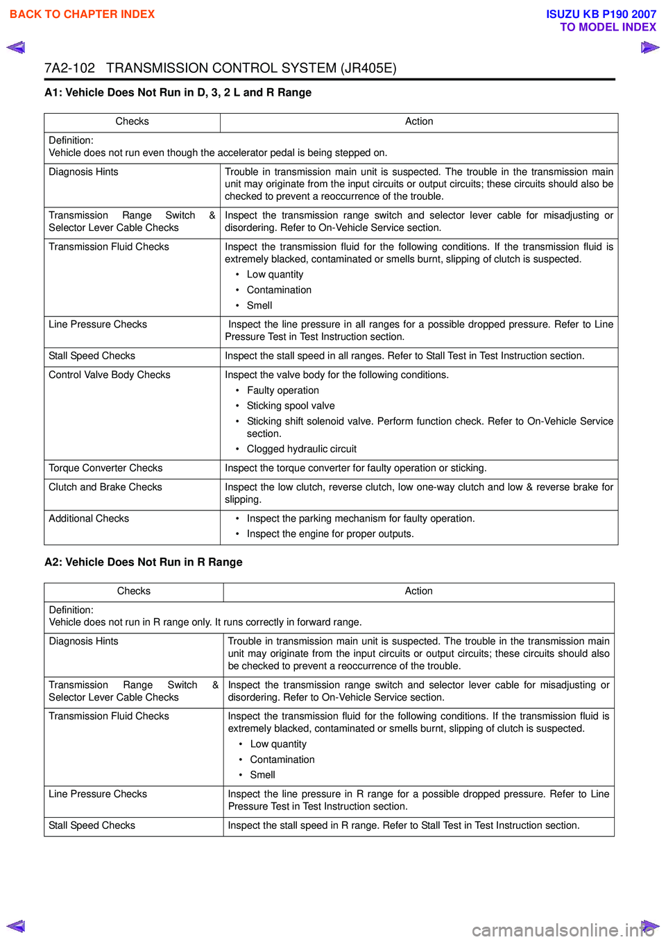
7A2-102 TRANSMISSION CONTROL SYSTEM (JR405E)
A1: Vehicle Does Not Run in D, 3, 2 L and R Range
A2: Vehicle Does Not Run in R Range
ChecksAction
Definition:
Vehicle does not run even though the accelerator pedal is being stepped on.
Diagnosis Hints Trouble in transmission main unit is suspected. The trouble in the transmission main
unit may originate from the input circuits or output circuits; these circuits should also be
checked to prevent a reoccurrence of the trouble.
Transmission Range Switch &
Selector Lever Cable Checks Inspect the transmission range switch and selector lever cable for misadjusting or
disordering. Refer to On-Vehicle Service section.
Transmission Fluid Checks Inspect the transmission fluid for the following conditions. If the transmission fluid is
extremely blacked, contaminated or smells burnt, slipping of clutch is suspected.
• Low quantity
• Contamination
•Smell
Line Pressure Checks Inspect the line pressure in all ranges for a possible dropped pressure. Refer to Line
Pressure Test in Test Instruction section.
Stall Speed Checks Inspect the stall speed in all ranges. Refer to Stall Test in Test Instruction section.
Control Valve Body Checks Inspect the valve body for the following conditions.
• Faulty operation
• Sticking spool valve
• Sticking shift solenoid valve. Perform function check. Refer to On-Vehicle Service section.
• Clogged hydraulic circuit
Torque Converter Checks Inspect the torque converter for faulty operation or sticking.
Clutch and Brake Checks Inspect the low clutch, reverse clutch, low one-way clutch and low & reverse brake for
slipping.
Additional Checks • Inspect the parking mechanism for faulty operation.
• Inspect the engine for proper outputs.
Checks Action
Definition:
Vehicle does not run in R range only. It runs correctly in forward range.
Diagnosis Hints Trouble in transmission main unit is suspected. The trouble in the transmission main
unit may originate from the input circuits or output circuits; these circuits should also
be checked to prevent a reoccurrence of the trouble.
Transmission Range Switch &
Selector Lever Cable Checks Inspect the transmission range switch and selector lever cable for misadjusting or
disordering. Refer to On-Vehicle Service section.
Transmission Fluid Checks Inspect the transmission fluid for the following conditions. If the transmission fluid is
extremely blacked, contaminated or smells burnt, slipping of clutch is suspected.
• Low quantity
• Contamination
•Smell
Line Pressure Checks Inspect the line pressure in R range for a possible dropped pressure. Refer to Line
Pressure Test in Test Instruction section.
Stall Speed Checks Inspect the stall speed in R range. Refer to Stall Test in Test Instruction section.
BACK TO CHAPTER INDEX
TO MODEL INDEX
ISUZU KB P190 2007
Page 4387 of 6020
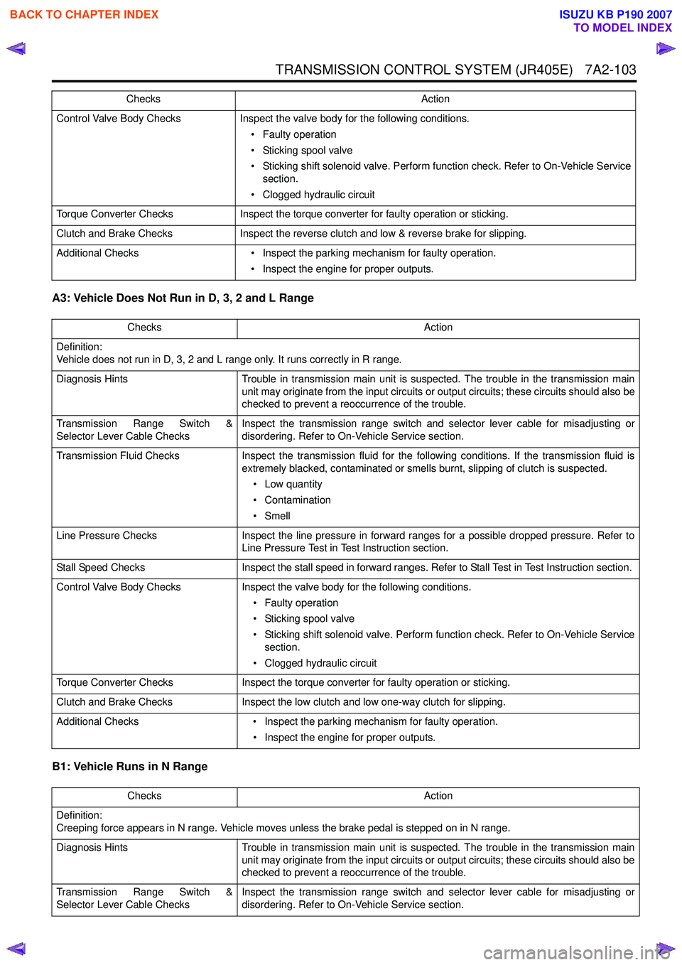
TRANSMISSION CONTROL SYSTEM (JR405E) 7A2-103
A3: Vehicle Does Not Run in D, 3, 2 and L Range
B1: Vehicle Runs in N Range
Control Valve Body Checks Inspect the valve body for the following conditions.
• Faulty operation
• Sticking spool valve
• Sticking shift solenoid valve. Perform function check. Refer to On-Vehicle Service section.
• Clogged hydraulic circuit
Torque Converter Checks Inspect the torque converter for faulty operation or sticking.
Clutch and Brake Checks Inspect the reverse clutch and low & reverse brake for slipping.
Additional Checks • Inspect the parking mechanism for faulty operation.
• Inspect the engine for proper outputs.
Checks
Action
Checks Action
Definition:
Vehicle does not run in D, 3, 2 and L range only. It runs correctly in R range.
Diagnosis Hints Trouble in transmission main unit is suspected. The trouble in the transmission main
unit may originate from the input circuits or output circuits; these circuits should also be
checked to prevent a reoccurrence of the trouble.
Transmission Range Switch &
Selector Lever Cable Checks Inspect the transmission range switch and selector lever cable for misadjusting or
disordering. Refer to On-Vehicle Service section.
Transmission Fluid Checks Inspect the transmission fluid for the following conditions. If the transmission fluid is
extremely blacked, contaminated or smells burnt, slipping of clutch is suspected.
• Low quantity
• Contamination
•Smell
Line Pressure Checks Inspect the line pressure in forward ranges for a possible dropped pressure. Refer to
Line Pressure Test in Test Instruction section.
Stall Speed Checks Inspect the stall speed in forward ranges. Refer to Stall Test in Test Instruction section.
Control Valve Body Checks Inspect the valve body for the following conditions.
• Faulty operation
• Sticking spool valve
• Sticking shift solenoid valve. Perform function check. Refer to On-Vehicle Service section.
• Clogged hydraulic circuit
Torque Converter Checks Inspect the torque converter for faulty operation or sticking.
Clutch and Brake Checks Inspect the low clutch and low one-way clutch for slipping.
Additional Checks • Inspect the parking mechanism for faulty operation.
• Inspect the engine for proper outputs.
Checks Action
Definition:
Creeping force appears in N range. Vehicle moves unless the brake pedal is stepped on in N range.
Diagnosis Hints Trouble in transmission main unit is suspected. The trouble in the transmission main
unit may originate from the input circuits or output circuits; these circuits should also be
checked to prevent a reoccurrence of the trouble.
Transmission Range Switch &
Selector Lever Cable Checks Inspect the transmission range switch and selector lever cable for misadjusting or
disordering. Refer to On-Vehicle Service section.
BACK TO CHAPTER INDEX
TO MODEL INDEX
ISUZU KB P190 2007
Page 4388 of 6020
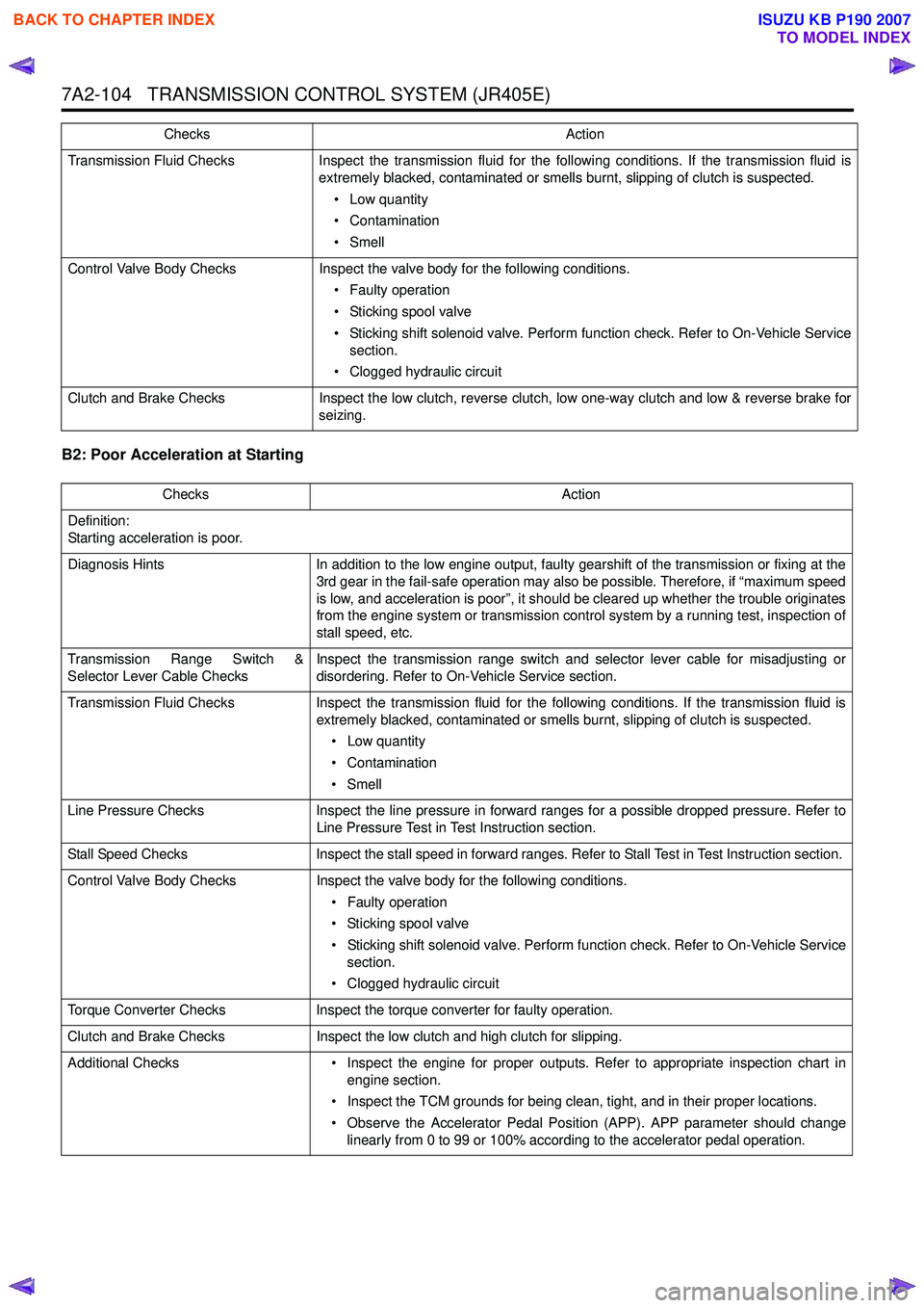
7A2-104 TRANSMISSION CONTROL SYSTEM (JR405E)
B2: Poor Acceleration at Starting
Transmission Fluid ChecksInspect the transmission fluid for the following conditions. If the transmission fluid is
extremely blacked, contaminated or smells burnt, slipping of clutch is suspected.
• Low quantity
• Contamination
•Smell
Control Valve Body Checks Inspect the valve body for the following conditions.
• Faulty operation
• Sticking spool valve
• Sticking shift solenoid valve. Perform function check. Refer to On-Vehicle Service section.
• Clogged hydraulic circuit
Clutch and Brake Checks Inspect the low clutch, reverse clutch, low one-way clutch and low & reverse brake for
seizing.
Checks
Action
ChecksAction
Definition:
Starting acceleration is poor.
Diagnosis Hints In addition to the low engine output, faulty gearshift of the transmission or fixing at the
3rd gear in the fail-safe operation may also be possible. Therefore, if “maximum speed
is low, and acceleration is poor”, it should be cleared up whether the trouble originates
from the engine system or transmission control system by a running test, inspection of
stall speed, etc.
Transmission Range Switch &
Selector Lever Cable Checks Inspect the transmission range switch and selector lever cable for misadjusting or
disordering. Refer to On-Vehicle Service section.
Transmission Fluid Checks Inspect the transmission fluid for the following conditions. If the transmission fluid is
extremely blacked, contaminated or smells burnt, slipping of clutch is suspected.
• Low quantity
• Contamination
•Smell
Line Pressure Checks Inspect the line pressure in forward ranges for a possible dropped pressure. Refer to
Line Pressure Test in Test Instruction section.
Stall Speed Checks Inspect the stall speed in forward ranges. Refer to Stall Test in Test Instruction section.
Control Valve Body Checks Inspect the valve body for the following conditions.
• Faulty operation
• Sticking spool valve
• Sticking shift solenoid valve. Perform function check. Refer to On-Vehicle Service section.
• Clogged hydraulic circuit
Torque Converter Checks Inspect the torque converter for faulty operation.
Clutch and Brake Checks Inspect the low clutch and high clutch for slipping.
Additional Checks • Inspect the engine for proper outputs. Refer to appropriate inspection chart in
engine section.
• Inspect the TCM grounds for being clean, tight, and in their proper locations.
• Observe the Accelerator Pedal Position (APP). APP parameter should change linearly from 0 to 99 or 100% according to the accelerator pedal operation.
BACK TO CHAPTER INDEX
TO MODEL INDEX
ISUZU KB P190 2007