2007 ISUZU KB P190 service
[x] Cancel search: servicePage 4436 of 6020
7A2-152 TRANSMISSION CONTROL SYSTEM (JR405E)
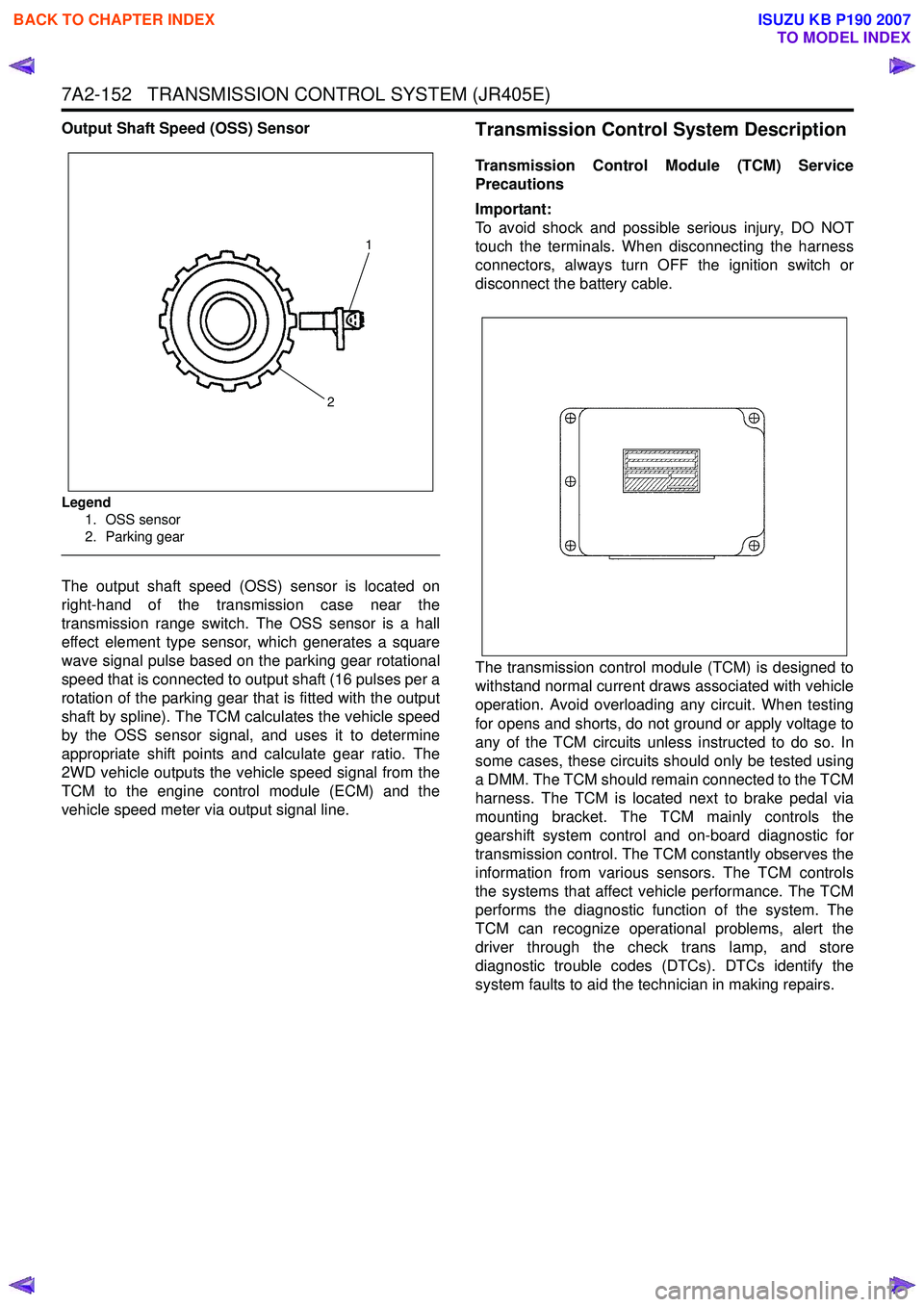
Output Shaft Speed (OSS) Sensor
Legend1. OSS sensor
2. Parking gear
The output shaft speed (OSS) sensor is located on
right-hand of the transmission case near the
transmission range switch. The OSS sensor is a hall
effect element type sensor, which generates a square
wave signal pulse based on the parking gear rotational
speed that is connected to output shaft (16 pulses per a
rotation of the parking gear that is fitted with the output
shaft by spline). The TCM calculates the vehicle speed
by the OSS sensor signal, and uses it to determine
appropriate shift points and calculate gear ratio. The
2WD vehicle outputs the vehicle speed signal from the
TCM to the engine control module (ECM) and the
vehicle speed meter via output signal line.
Transmission Control System Description
Transmission Control Module (TCM) Service
Precautions
Important:
To avoid shock and possible serious injury, DO NOT
touch the terminals. When disconnecting the harness
connectors, always turn OFF the ignition switch or
disconnect the battery cable.
The transmission control module (TCM) is designed to
withstand normal current draws associated with vehicle
operation. Avoid overloading any circuit. When testing
for opens and shorts, do not ground or apply voltage to
any of the TCM circuits unless instructed to do so. In
some cases, these circuits should only be tested using
a DMM. The TCM should remain connected to the TCM
harness. The TCM is located next to brake pedal via
mounting bracket. The TCM mainly controls the
gearshift system control and on-board diagnostic for
transmission control. The TCM constantly observes the
information from various sensors. The TCM controls
the systems that affect vehicle performance. The TCM
performs the diagnostic function of the system. The
TCM can recognize operational problems, alert the
driver through the check trans lamp, and store
diagnostic trouble codes (DTCs). DTCs identify the
system faults to aid the technician in making repairs.
1
2
BACK TO CHAPTER INDEX
TO MODEL INDEX
ISUZU KB P190 2007
Page 4438 of 6020
7A2-154 TRANSMISSION CONTROL SYSTEM (JR405E)
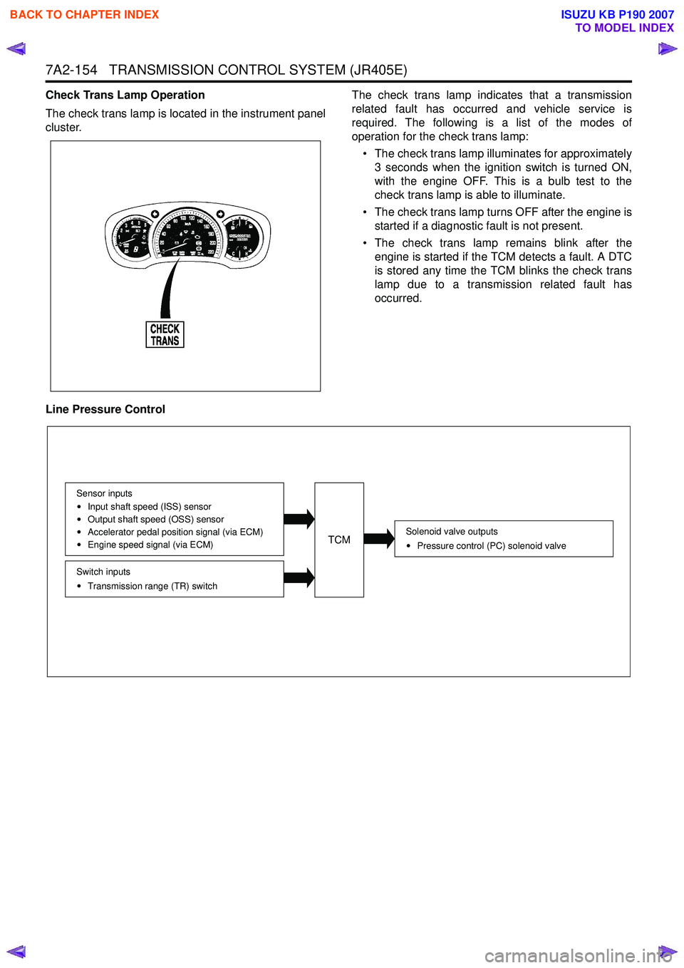
Check Trans Lamp Operation
The check trans lamp is located in the instrument panel
cluster. The check trans lamp indicates that a transmission
related fault has occurred and vehicle service is
required. The following is a list of the modes of
operation for the check trans lamp:
• The check trans lamp illuminates for approximately 3 seconds when the ignition switch is turned ON,
with the engine OFF. This is a bulb test to the
check trans lamp is able to illuminate.
• The check trans lamp turns OFF after the engine is started if a diagnostic fault is not present.
• The check trans lamp remains blink after the engine is started if the TCM detects a fault. A DTC
is stored any time the TCM blinks the check trans
lamp due to a transmission related fault has
occurred.
Line Pressure Control
Solenoid valve outputs Pressure control (PC) solenoid valve
Switch inputsTransmission range (TR) switch
Sensor inputs
Input shaft speed (ISS) sensor
Output shaft speed (OSS) sensor
Accelerator pedal position signal (via ECM)
Engine speed signal (via ECM)TCM
BACK TO CHAPTER INDEX
TO MODEL INDEX
ISUZU KB P190 2007
Page 4455 of 6020
ON-VEHICLE SERVICE (JR405E) 7A3-1
SECTION 7A3
ON-VEHICLE SERVICE (JR405E)
TABLE OF CONTENTS
PAGE
Description ................................................................................................................... ... 7A3 – 2
Automatic Transmission Fluid (ATF) ............................................................................ 7A3 – 2
ATF Level ..................................................................................................................... .... 7A3 – 2
ATF Change .................................................................................................................... . 7A3 – 3
Transmission Control Module (TCM) ............................................................................ 7A3 – 5
Inhibitor Switch .............................................................................................................. . 7A3 – 6
Speed Sensor .................................................................................................................. 7A3 – 8
Turbine Sensor ............................................................................................................... 7A3 – 9
Power and 3rd Start Switch ........................................................................................... 7A3 – 9
Select Lever .................................................................................................................. ... 7A3 –10
Shift Cable ................................................................................................................... .... 7A3 –13
Solenoids, Oil Pressure Switch and Oil Temperature Sensor .................................... 7A3 –16
Control Valve Assembly ................................................................................................. 7A3 –1 8
Flushing the Transmission Fluid Cooler and Line ...................................................... 7A3 –19
Transmission Assembly ................................................................................................. 7A3 –20
Special Service Tool ....................................................................................................... 7A 3 –23
BACK TO CHAPTER INDEX
TO MODEL INDEX
ISUZU KB P190 2007
Page 4456 of 6020
7A3-2 ON-VEHICLE SERVICE (JR405E)
DESCRIPTION
Before performing on-vehicle service on the automatic
transmission, check that the engine idling speed and
general engine condition are normal.
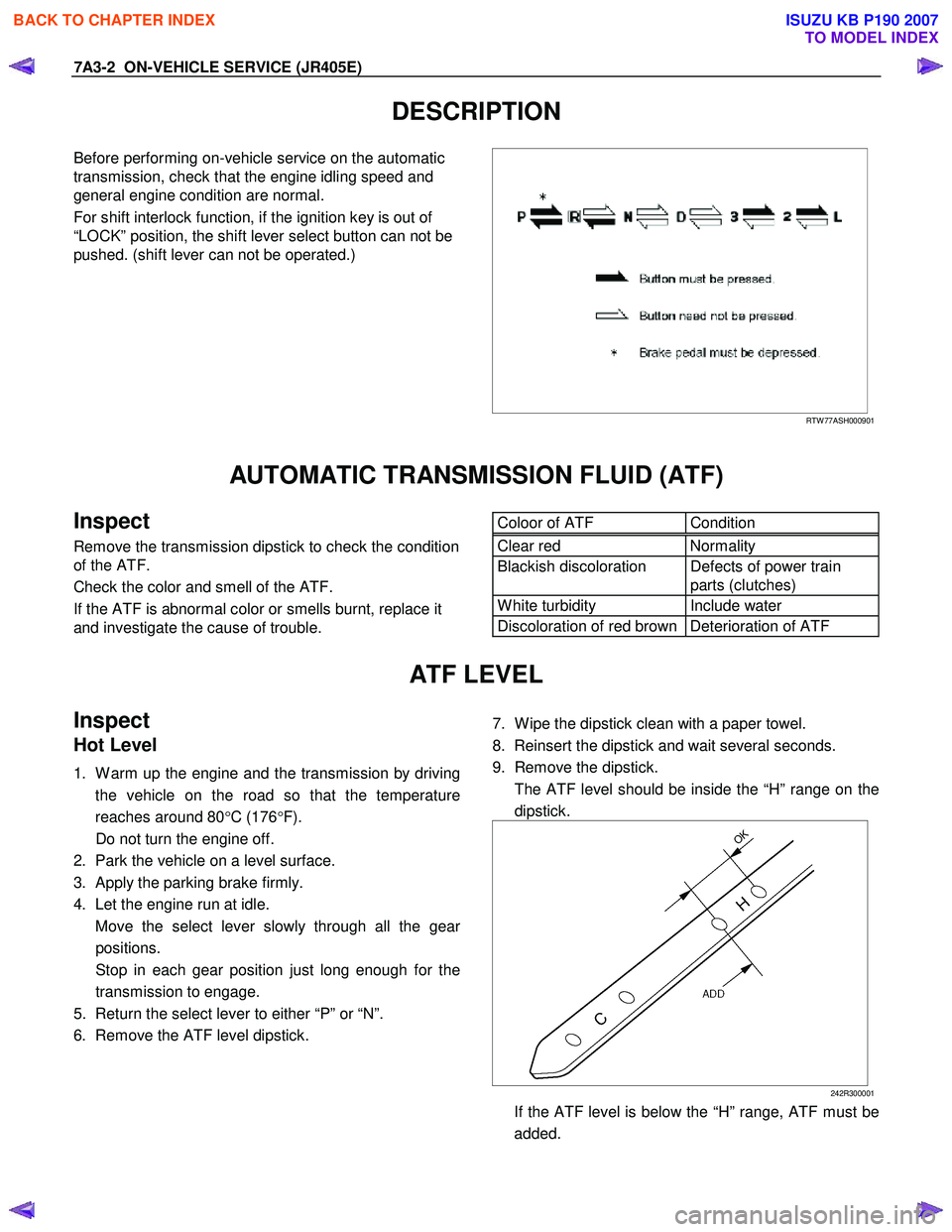
For shift interlock function, if the ignition key is out of
“LOCK” position, the shift lever select button can not be
pushed. (shift lever can not be operated.)
RTW 77ASH000901
AUTOMATIC TRANSMISSION FLUID (ATF)
Inspect
Remove the transmission dipstick to check the condition
of the ATF.
Check the color and smell of the ATF.
If the ATF is abnormal color or smells burnt, replace it
and investigate the cause of trouble.
Coloor of ATF Condition Clear red Normality
Blackish discoloration Defects of power train
parts (clutches)
W hite turbidity Include water
Discoloration of red brown Deterioration of ATF
ATF LEVEL
Inspect
Hot Level
1. W arm up the engine and the transmission by driving
the vehicle on the road so that the temperature
reaches around 80 °C (176 °F).
Do not turn the engine off.
2. Park the vehicle on a level surface.
3. Apply the parking brake firmly.
4. Let the engine run at idle.
Move the select lever slowly through all the gea
r
positions.
Stop in each gear position just long enough for the transmission to engage.
5. Return the select lever to either “P” or “N”.
6. Remove the ATF level dipstick.
7. W ipe the dipstick clean with a paper towel.
8. Reinsert the dipstick and wait several seconds.
9. Remove the dipstick.
The ATF level should be inside the “H” range on the dipstick.
242R300001
If the ATF level is below the “H” range, ATF must be added.
BACK TO CHAPTER INDEX
TO MODEL INDEX
ISUZU KB P190 2007
Page 4457 of 6020
ON-VEHICLE SERVICE (JR405E) 7A3-3
Cold Level
The vehicle must not have been driven so that the
temperature reaches around 20 °C (68 °F) before the
cold level check is made.
1. Park the vehicle on a level surface.
2. Apply the parking brake firmly.
3. Start the engine and allow it to warm up.
The engine coolant temperature gauge needle should be midway between the “C” mark and “H”
mark.
4. Let the engine run at idle.
Move the select lever slowly through all the gea
r
ranges.
Stop in each range just long enough for the transmission to engage.
5. Return the select lever either “P” or “N”.
6. Remove the ATF level dipstick.
7. W ipe the dipstick clean with a paper towel.
8. Reinsert the dipstick and wait several seconds.
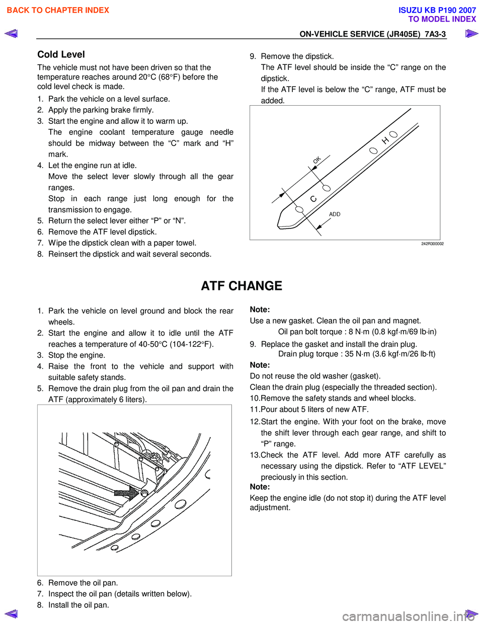
9. Remove the dipstick.
The ATF level should be inside the “C” range on the dipstick.
If the ATF level is below the “C” range, ATF must be added.
242R300002
ATF CHANGE
1. Park the vehicle on level ground and block the rear
wheels.
2. Start the engine and allow it to idle until the ATF reaches a temperature of 40-50 °C (104-122 °F).
3. Stop the engine.
4. Raise the front to the vehicle and support with suitable safety stands.
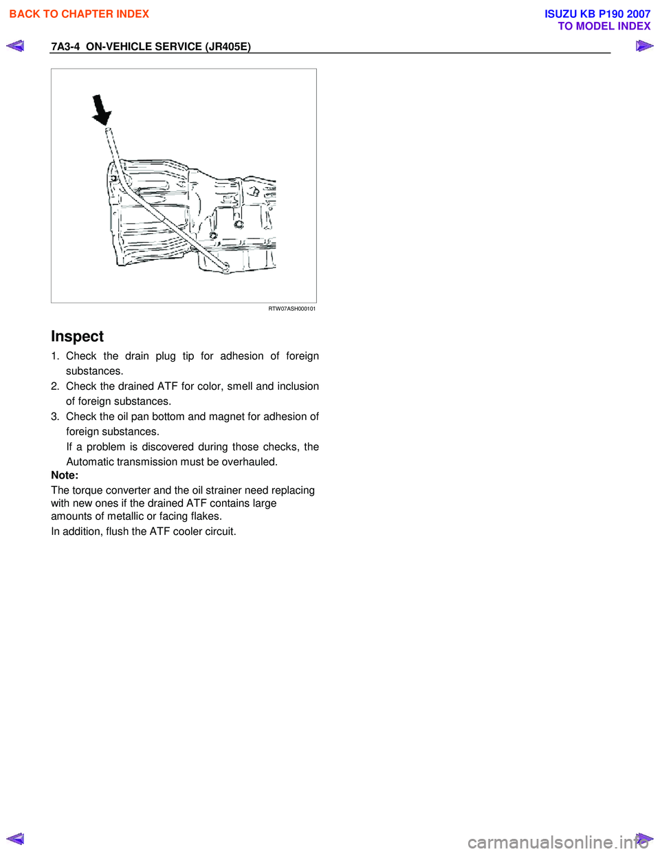
5. Remove the drain plug from the oil pan and drain the ATF (approximately 6 liters).
6. Remove the oil pan.
7. Inspect the oil pan (details written below).
8. Install the oil pan.
Note:
Use a new gasket. Clean the oil pan and magnet.
Oil pan bolt torque : 8 N ⋅m (0.8 kgf ⋅m/69 lb ⋅in)
9. Replace the gasket and install the drain plug.
Drain plug torque : 35 N ⋅m (3.6 kgf ⋅m/26 lb ⋅ft)
Note:
Do not reuse the old washer (gasket).
Clean the drain plug (especially the threaded section).
10.Remove the safety stands and wheel blocks.
11.Pour about 5 liters of new ATF.
12. Start the engine. W ith your foot on the brake, move the shift lever through each gear range, and shift to
“P” range.
13.Check the ATF level. Add more ATF carefully as necessary using the dipstick. Refer to “ATF LEVEL”
preciously in this section.
Note:
Keep the engine idle (do not stop it) during the ATF level
adjustment.
BACK TO CHAPTER INDEX
TO MODEL INDEX
ISUZU KB P190 2007
Page 4458 of 6020
7A3-4 ON-VEHICLE SERVICE (JR405E)
RTW 07ASH000101
Inspect
1. Check the drain plug tip for adhesion of foreign
substances.
2. Check the drained ATF for color, smell and inclusion of foreign substances.
3. Check the oil pan bottom and magnet for adhesion o
f
foreign substances.
If a problem is discovered during those checks, the Automatic transmission must be overhauled.
Note:
The torque converter and the oil strainer need replacing
with new ones if the drained ATF contains large
amounts of metallic or facing flakes.
In addition, flush the ATF cooler circuit.
BACK TO CHAPTER INDEX
TO MODEL INDEX
ISUZU KB P190 2007
Page 4459 of 6020
ON-VEHICLE SERVICE (JR405E) 7A3-5
TRANSMISSION CONTROL MODULE (TCM)
RTW 37ALF001901
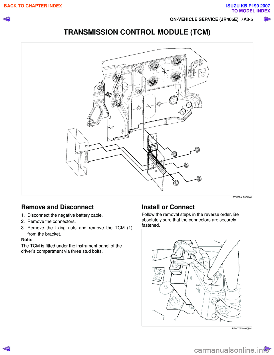
Remove and Disconnect
1. Disconnect the negative battery cable.
2. Remove the connectors.
3. Remove the fixing nuts and remove the TCM (1) from the bracket.
Note:
The TCM is fitted under the instrument panel of the
driver’s compartment via three stud bolts.
Install or Connect
Follow the removal steps in the reverse order. Be
absolutely sure that the connectors are securely
fastened.
RTW 77ASH000801
BACK TO CHAPTER INDEX
TO MODEL INDEX
ISUZU KB P190 2007
Page 4460 of 6020
7A3-6 ON-VEHICLE SERVICE (JR405E)
INHIBITOR SWITCH
The inhibitor switch is attached to the right side of the
transmission.
Inspect
1. Block the wheels.
2. Disconnect the negative battery cable.
3. Disconnect the harness connectors.
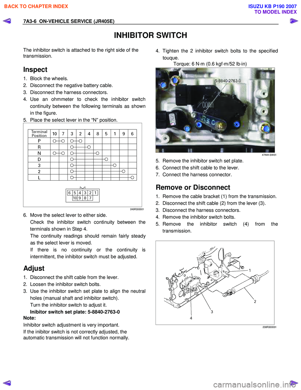
4. Use an ohmmeter to check the inhibitor switch continuity between the following terminals as shown
in the figure.
5. Place the select lever in the “N” position.
249R300001
6. Move the select lever to either side.
Check the inhibitor switch continuity between the terminals shown in Step 4.
The continuity readings should remain fairly stead
y
as the select lever is moved.
If there is no continuity or the continuity is intermittent, the inhibitor switch must be adjusted.
Adjust
1. Disconnect the shift cable from the lever.
2. Loosen the inhibitor switch bolts.
3. Use the inhibitor switch set plate to align the neutral holes (manual shaft and inhibitor switch).
Turn the inhibitor switch to adjust it.
Inibitor switch set plate: 5-8840-2763-0
Note:
Inhibitor switch adjustment is very important.
If the inibitor switch is not correctly adjusted, the
automatic transmission will not function normally.
4. Tighten the 2 inhibitor switch bolts to the specified
touque.
Torque: 6 N·m (0.6 kgf·m/52 lb·in)
47INH-SW 01
5. Remove the inhibitor switch set plate.
6. Connect the shift cable to the lever.
7. Connect the harness connector.
Remove or Disconnect
1. Remove the cable bracket (1) from the transmission.
2. Disconnect the shift cable (2) from the lever (3).
3. Disconnect the harness connectors.
4. Remove the inhibitor switch bolts.
5. Remove the inhibitor switch (4) from the transmission.
238R300001
BACK TO CHAPTER INDEX
TO MODEL INDEX
ISUZU KB P190 2007