2007 ISUZU KB P190 service
[x] Cancel search: servicePage 3907 of 6020
Automatic Transmission – 4L60E – Electrical Diagnosis Page 7C2–121
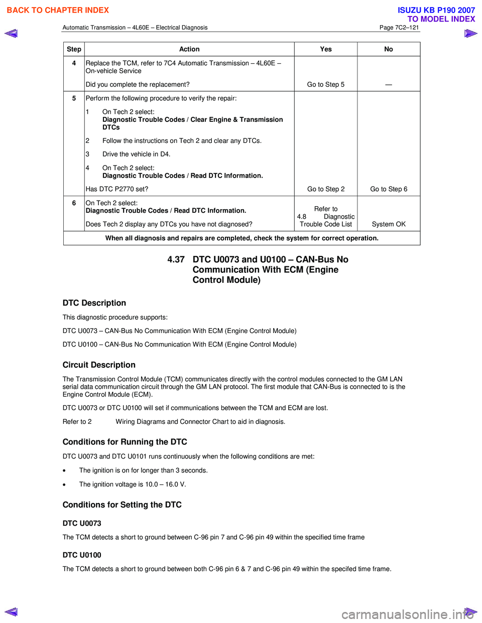
Step Action Yes No
4 Replace the TCM, refer to 7C4 Automatic Transmission – 4L60E –
On-vehicle Service
Did you complete the replacement? Go to Step 5 —
5 Perform the following procedure to verify the repair:
1 On Tech 2 select: Diagnostic Trouble Codes / Clear Engine & Transmission
DTCs
2 Follow the instructions on Tech 2 and clear any DTCs.
3 Drive the vehicle in D4.
4 On Tech 2 select:
Diagnostic Trouble Codes / Read DTC Information.
Has DTC P2770 set? Go to Step 2 Go to Step 6
6 On Tech 2 select:
Diagnostic Trouble Codes / Read DTC Information.
Does Tech 2 display any DTCs you have not diagnosed? Refer to
4.8 Diagnostic Trouble Code List System OK
When all diagnosis and repairs are completed, check the
system for correct operation.
4.37 DTC U0073 and U0100 – CAN-Bus No
Communication With ECM (Engine
Control Module)
DTC Description
This diagnostic procedure supports:
DTC U0073 – CAN-Bus No Communication W ith ECM (Engine Control Module)
DTC U0100 – CAN-Bus No Communication W ith ECM (Engine Control Module)
Circuit Description
The Transmission Control Module (TCM) communicates directly with the control modules connected to the GM LAN
serial data communication circuit through the GM LAN protocol. The first module that CAN-Bus is connected to is the
Engine Control Module (ECM).
DTC U0073 or DTC U0100 will set if communications between the TCM and ECM are lost.
Refer to 2 W iring Diagrams and Connector Chart to aid in diagnosis.
Conditions for Running the DTC
DTC U0073 and DTC U0101 runs continuously when the following conditions are met:
• The ignition is on for longer than 3 seconds.
• The ignition voltage is 10.0 – 16.0 V.
Conditions for Setting the DTC
DTC U0073
The TCM detects a short to ground between C-96 pin 7 and C-96 pin 49 within the specified time frame
DTC U0100
The TCM detects a short to ground between both C-96 pin 6 & 7 and C-96 pin 49 within the specifed time frame.
BACK TO CHAPTER INDEX
TO MODEL INDEX
ISUZU KB P190 2007
Page 3914 of 6020
Automatic Transmission – 4L60E – On-vehicle Servicing Page 7C4–1
7C4
Automatic Transmission – 4L60E –
On-vehicle Servicing
ATTENTION
Before performing any service operation or other procedure described in this Section, refer to General Information Warnings, Cautions and Notes for correct workshop practices with regard to safety and/or property damage.
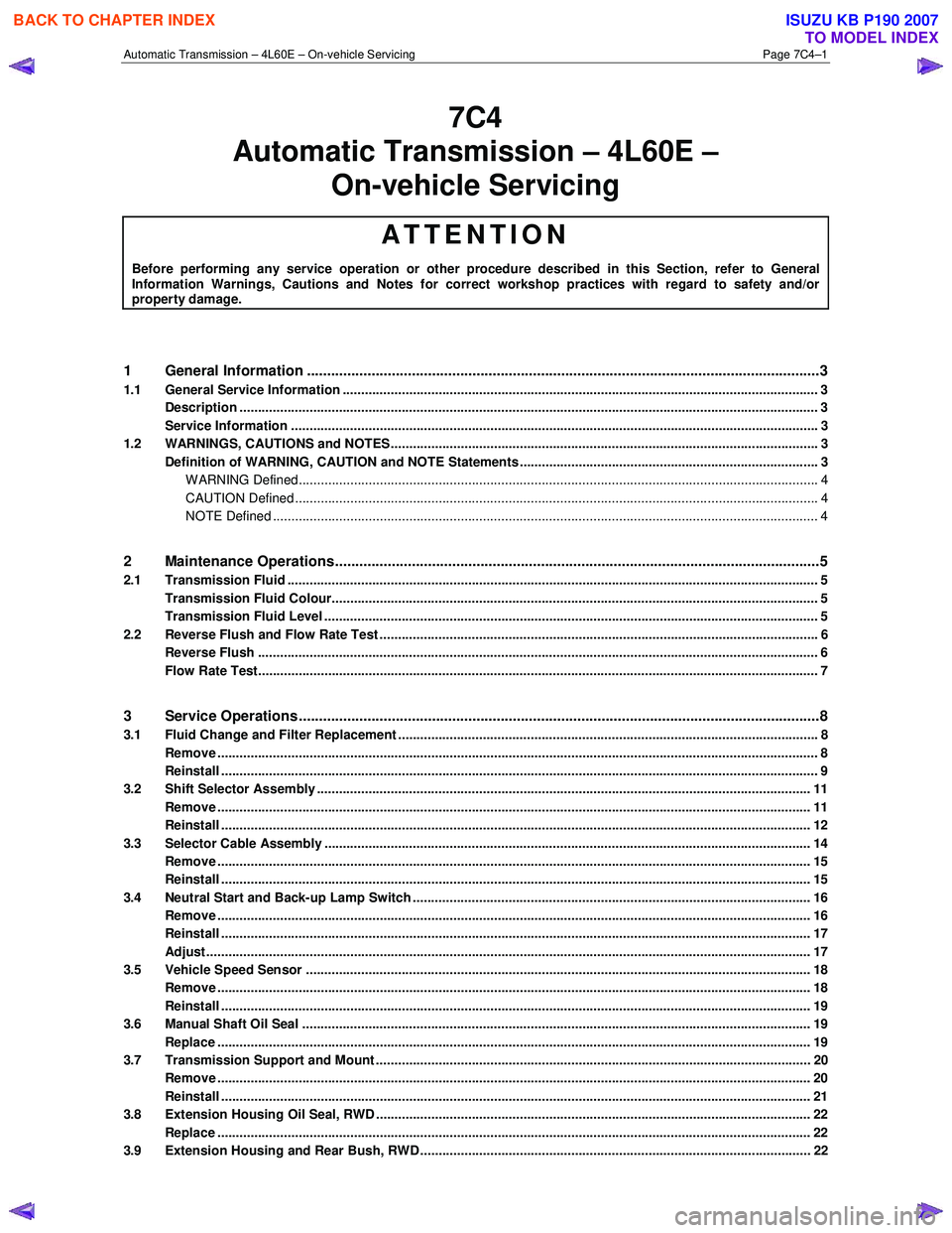
1 General Information ............................................................................................................ ...................3
1.1 General Service Information ................................................................................................................................. 3
Description ............................................................................................................................................................. 3
Service Information ............................................................................................................ ................................... 3
1.2 WARNINGS, CAUTIONS and NOTES................................................................................................... ................. 3
Definition of WARNING, CAUTION and NOTE Statements ............................................................................. .... 3
WARNING Defined............................................................................................................................................. 4
CAUTION Defined .............................................................................................................................................. 4
NOTE Defined .................................................................................................................................................... 4
2 Maintenance Operations......................................................................................................... ...............5
2.1 Transmission Fluid ................................................................................................................................................ 5
Transmission Fluid Colour...................................................................................................... .............................. 5
Transmission Fluid Level ...................................................................................................................................... 5
2.2 Reverse Flush and Flow Rate Test ............................................................................................... ........................ 6
Reverse Flush ........................................................................................................................................................ 6
Flow Rate Test........................................................................................................................................................ 7
3 Service Operations ............................................................................................................. ....................8
3.1 Fluid Change and Filter Replacement ............................................................................................ ...................... 8
Remove ................................................................................................................................................................... 8
Reinstall .................................................................................................................................................................. 9
3.2 Shift Selector Assembly ...................................................................................................................................... 11
Remove ................................................................................................................................................................. 11
Reinstall ................................................................................................................................................................ 12
3.3 Selector Cable Assembly .................................................................................................................................... 14
Remove ................................................................................................................................................................. 15
Reinstall ................................................................................................................................................................ 15
3.4 Neutral Start and Back-up Lamp Switch ............................................................................................................ 16
Remove ................................................................................................................................................................. 16
Reinstall ................................................................................................................................................................ 17
Adjust .................................................................................................................................................................... 17
3.5 Vehicle Speed Sensor ......................................................................................................................................... 18
Remove ................................................................................................................................................................. 18
Reinstall ................................................................................................................................................................ 19
3.6 Manual Shaft Oil Seal .......................................................................................................................................... 19
Replace ................................................................................................................................................................. 19
3.7 Transmission Support and Mount ................................................................................................. ..................... 20
Remove ................................................................................................................................................................. 20
Reinstall ................................................................................................................................................................ 21
3.8 Extension Housing Oil Seal, RWD ...................................................................................................................... 22
Replace ................................................................................................................................................................. 22
3.9 Extension Housing and Rear Bush, RWD ........................................................................................... ............... 22
BACK TO CHAPTER INDEX
TO MODEL INDEX
ISUZU KB P190 2007
Page 3916 of 6020
Automatic Transmission – 4L60E – On-vehicle Servicing Page 7C4–3
1 General Information
This Section describes the removal and reinstallation procedures of the four speed 4L60E hydra-matic automatic
transmission as well as the service operations which can be performed with the transmission still fitted to the vehicle.
1.1 General Service Information
Description
The shift selector mechanism is linked to the transmission manual shaft with a selector cable. A heat protector is fitted
over the neutral start and back-up switch and manual shaft select lever.
For rear wheel drive (RWD) vehicles an extension housing is fitted to the rear of the transmission case.
Four wheel drive (4W D) vehicles have an adaptor housing and transfer case fitted to the rear of the transmission case,
for description and service operation refer to 7D Transfer Case and Adaptor Housing.
The four speed 4L60E hydra-matic automatic transmission is fitted with a filler tube, a breather hose and a vent pipe for
hot fluid overflow.
The transmission fluid is driven through a cooler within the radiator via the cooler line/hose assemblies to maintain
normal operating temperature.
Service Information
Throughout the service operations within this
Section, when handling retaining clips, using
compressed air or cleaning fluids, wear safety
equipment to avoid personal injury.
Refer to 7C1 Automatic Transmission – 4L60E – General Information for the following:
• information relating to mechanical and electrical operations,
• abbreviations, transmission specifications, special tools and torque wrench specifications,
• servicing, cleaning and inspection procedure recommendations.
It is essential to read and understand the General Information, W arnings, Cautions and Service Notes contained in that
same Section, before any service operation is performed on the four speed 4L60E hydra-matic automatic transmission or
any associated components.
Failure to comply with the procedures and service notes can affect the reliable and efficient operation of this automatic
transmission.
1.2 WARNINGS, CAUTIONS and NOTES
This Section contains various W ARNINGS, CAUTIONS and NOTE statements that you must observe carefully to reduce
the risk of death or injury during service, repair procedures or vehicle operation. Incorrect service or repair procedures
may damage the vehicle or cause operational faults. W ARNINGS, CAUTION and NOTE statements are not exhaustive.
GM HOLDEN LTD can not possibly warn of all the potentially hazardous consequences of failure to follow these
instructions.
Definition of WARNING, CAUTION and NOTE Statements
Diagnosis and repair procedures in this Section contain both general and specific W ARNING, CAUTION and NOTE
statements. GM HOLDEN LTD is dedicated to the presentation of service information that helps the technician to
diagnose and repair the systems necessary for proper operation of the vehicle. Certain procedures may present a hazard
to the technician if they are not followed in the recommended manner. W ARNING, CAUTION and NOTE statements are
designed to help prevent these hazards from occurring, but not all hazards can be foreseen.
BACK TO CHAPTER INDEX
TO MODEL INDEX
ISUZU KB P190 2007
Page 3921 of 6020
Automatic Transmission – 4L60E – On-vehicle Servicing Page 7C4–8
3 Service Operations
3.1 Fluid Change and Filter Replacement
To avoid personal injury take note of the
following:
• Avoid accidental hot oil spillage by
performing fluid change only when the
transmission fluid is cold.
• Wear safety glasses and gloves when
using compressed air and cleaning fluids.
Remove
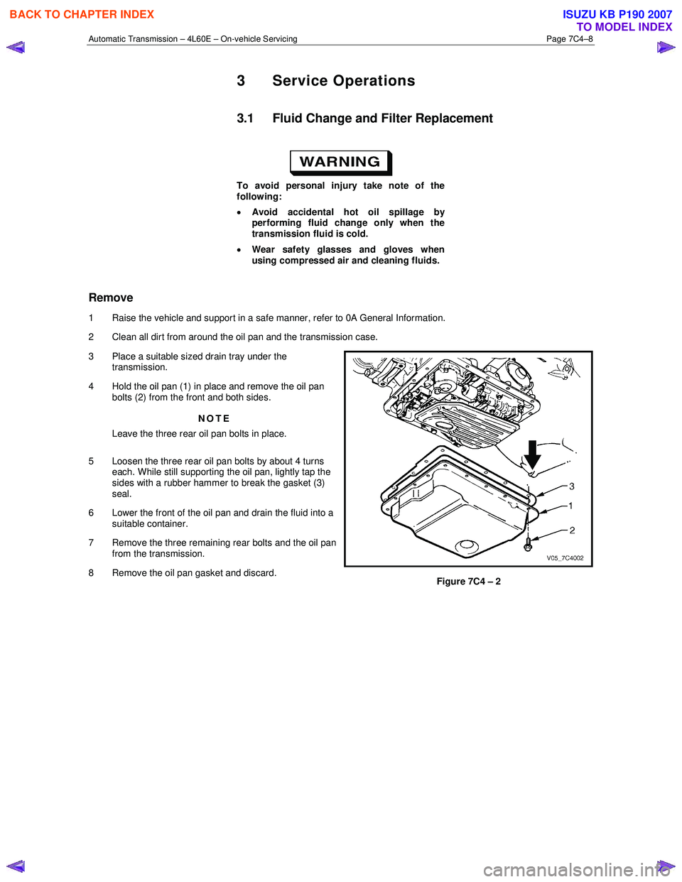
1 Raise the vehicle and support in a safe manner, refer to 0A General Information.
2 Clean all dirt from around the oil pan and the transmission case.
3 Place a suitable sized drain tray under the transmission.
4 Hold the oil pan (1) in place and remove the oil pan bolts (2) from the front and both sides.
NOTE
Leave the three rear oil pan bolts in place.
5 Loosen the three rear oil pan bolts by about 4 turns each. While still supporting the oil pan, lightly tap the
sides with a rubber hammer to break the gasket (3)
seal.
6 Lower the front of the oil pan and drain the fluid into a suitable container.
7 Remove the three remaining rear bolts and the oil pan from the transmission.
8 Remove the oil pan gasket and discard.
Figure 7C4 – 2
BACK TO CHAPTER INDEX
TO MODEL INDEX
ISUZU KB P190 2007
Page 3937 of 6020
Automatic Transmission – 4L60E – On-vehicle Servicing Page 7C4–24
7 Lubricate the outside of a new bush with automatic
transmission fluid to reduce the chance of material
pick-up.
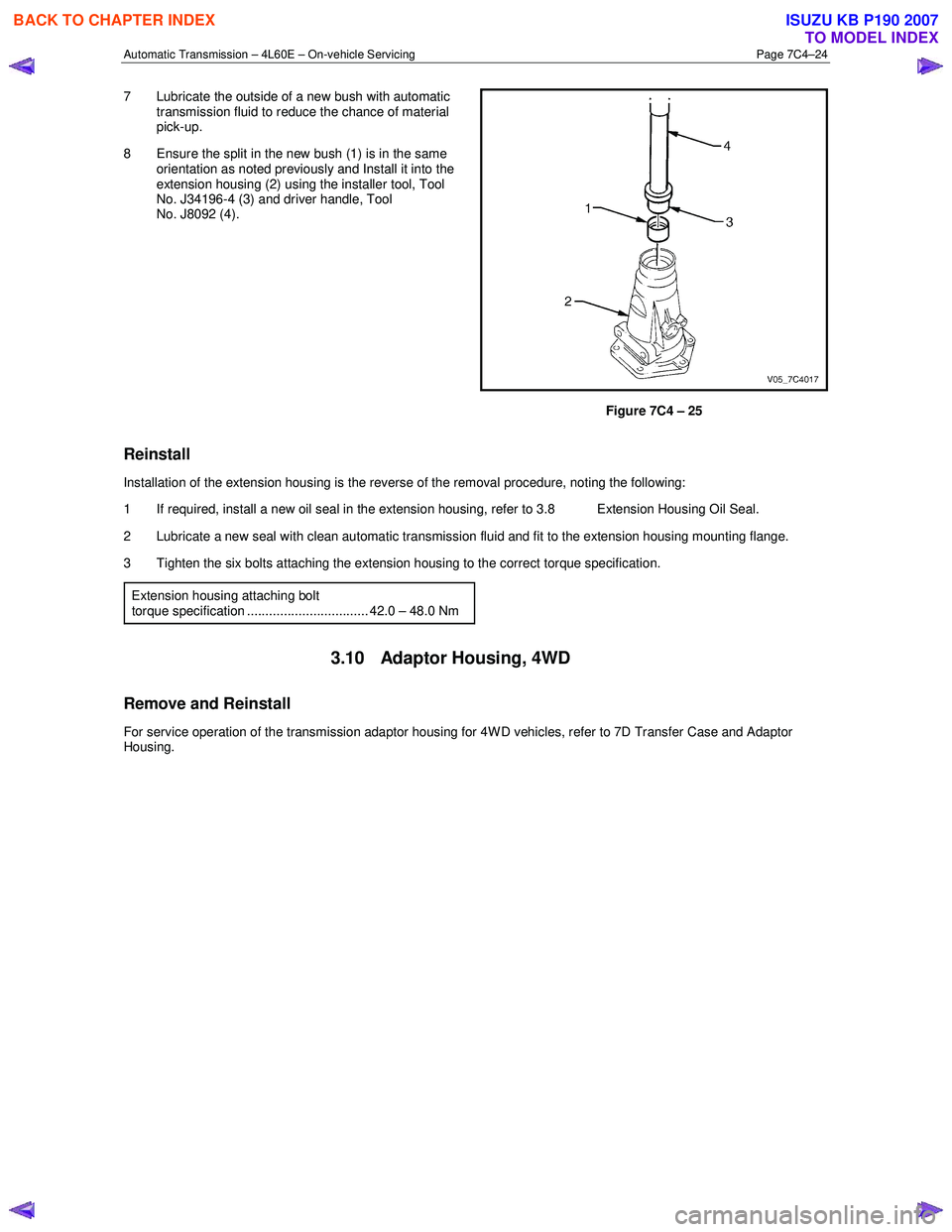
8 Ensure the split in the new bush (1) is in the same orientation as noted previously and Install it into the
extension housing (2) using the installer tool, Tool
No. J34196-4 (3) and driver handle, Tool
No. J8092 (4).
Figure 7C4 – 25
Reinstall
Installation of the extension housing is the reverse of the removal procedure, noting the following:
1 If required, install a new oil seal in the extension housing, refer to 3.8 Extension Housing Oil Seal.
2 Lubricate a new seal with clean automatic transmission fluid and fit to the extension housing mounting flange.
3 Tighten the six bolts attaching the extension housing to the correct torque specification.
Extension housing attaching bolt
torque specification ................................. 42.0 – 48.0 Nm
3.10 Adaptor Housing, 4WD
Remove and Reinstall
For service operation of the transmission adaptor housing for 4W D vehicles, refer to 7D Transfer Case and Adaptor
Housing.
BACK TO CHAPTER INDEX
TO MODEL INDEX
ISUZU KB P190 2007
Page 3938 of 6020
Automatic Transmission – 4L60E – On-vehicle Servicing Page 7C4–25
3.11 Shift Solenoid Locations
Location and Identification
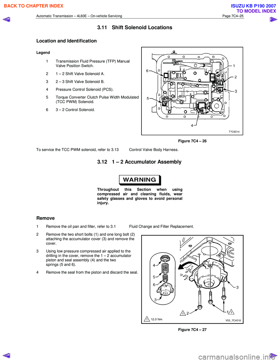
Legend
1 Transmission Fluid Pressure (TFP) Manual Valve Position Switch.
2 1 – 2 Shift Valve Solenoid A.
3 2 – 3 Shift Valve Solenoid B.
4 Pressure Control Solenoid (PCS).
5 Torque Converter Clutch Pulse W idth Modulated (TCC PWM) Solenoid.
6 3 – 2 Control Solenoid.
Figure 7C4 – 26
To service the TCC PWM solenoid, refer to 3.13 Control Valve Body Harness.
3.12 1 – 2 Accumulator Assembly
Throughout this Section when using
compressed air and cleaning fluids, wear
safety glasses and gloves to avoid personal
injury.
Remove
1 Remove the oil pan and filter, refer to 3.1 Fluid Change and Filter Replacement.
2 Remove the two short bolts (1) and one long bolt (2) attaching the accumulator cover (3) and remove the
cover.
3 Using low pressure compressed air applied to the drilling in the cover, remove the 1 – 2 accumulator
piston and seal assembly (4) and the two
springs (5 and 6).
4 Remove the seal from the piston and discard the seal.
Figure 7C4 – 27
BACK TO CHAPTER INDEX
TO MODEL INDEX
ISUZU KB P190 2007
Page 3961 of 6020
Automatic Transmission – 4L60E – On-vehicle Servicing Page 7C4–48
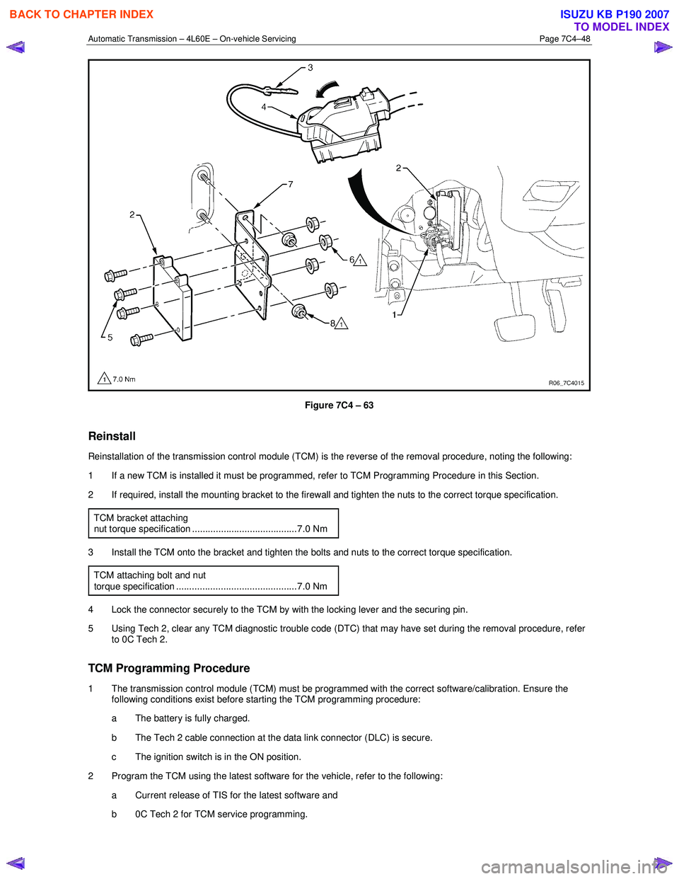
Figure 7C4 – 63
Reinstall
Reinstallation of the transmission control module (TCM) is the reverse of the removal procedure, noting the following:
1 If a new TCM is installed it must be programmed, refer to TCM Programming Procedure in this Section.
2 If required, install the mounting bracket to the firewall and tighten the nuts to the correct torque specification.
TCM bracket attaching
nut torque specification ........................................7.0 Nm
3 Install the TCM onto the bracket and tighten the bolts and nuts to the correct torque specification. TCM attaching bolt and nut
torque specification ..............................................7.0 Nm
4 Lock the connector securely to the TCM by with the locking lever and the securing pin.
5 Using Tech 2, clear any TCM diagnostic trouble code (DTC) that may have set during the removal procedure, refer to 0C Tech 2.
TCM Programming Procedure
1 The transmission control module (TCM) must be programmed with the correct software/calibration. Ensure the following conditions exist before starting the TCM programming procedure:
a The battery is fully charged.
b The Tech 2 cable connection at the data link connector (DLC) is secure.
c The ignition switch is in the ON position.
2 Program the TCM using the latest software for the vehicle, refer to the following: a Current release of TIS for the latest software and
b 0C Tech 2 for TCM service programming.
BACK TO CHAPTER INDEX
TO MODEL INDEX
ISUZU KB P190 2007
Page 3966 of 6020
Section 7A2 Transmission Control System .......................................................... ...... 4015 PAGE
Section 7A3 On Vehicle Service .................................................................................. 4134
Section 7A4 Unit Repair ................................................................................................ 4184
SECTION 7
TRANSMISSION
T A BLE OF CONTENTS
TRANSMISSION
AW30-40LE MODEL
BACK TO CHAPTER INDEX
TO MODEL INDEX
ISUZU KB P190 2007